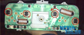
Here many people are interested in how to replace the old cam ignition with a new one. It's not that new. People call it Tyumenskoye.
|
- adjustment plate
- sensor
- rotor
- lock washer
- bolt
- wiring
- switch
written and drawn by: SHTRLZ
if anyone can help write to asya 257-318-122, thanks in advance
Folks, I installed such a carbolite sensor and took a switch for the contactless ignition system from a GAZelle from the same and the ignition coil is all fine, the spark is good, but there won’t be a problem with a spark until I screw the switch to ground, when it is shorted to ground, a spark immediately breaks out, I connect tightly and the ignition goes out it’s like a little one, but it starts with half a kick, another problem is while the ignition is on and the motorcycle is not started, the switch gets very hot when it’s started, everything is normal
But how to install BSZ on motorcycles with PM05 breaker (k-750 for example)?
There is one item missing from this manual. Namely, it is necessary to correctly set the gap between the rotor and the sensor to be 0.2-0.3 mm. With a large gap at low speeds, interruptions in spark formation are possible. As for the electronic unit, it has a very unpleasant feature. He perfectly produces a spark somewhere on a stand, in which there are ideal electrical circuits, and at the same time, he doesn’t want to work at all in his home place. Without going into unnecessary details, I can say that part of the scheme needs improvement. Personally, I rebuilt several copies, after which I have no problems at low speeds or in bad weather conditions.
The reed switch has a lot of inertia. it will take a long time to open
Ural motorcycles produced after the 90s have a contactless ignition system. But the predecessors of the happy owners of new iron horses also roam the expanses of Russia.
In the outback you can still see a rarity - a three-wheeled toiler based on the M-72. These older motorcycle models have a contact type ignition system.
Leave it to mechanics or install electronics
Perhaps not all older motorcycle models are running. The Ural motorcycle sits and rusts in my grandfather’s barn because it won’t start.
The wheels are spinning, the engine is not jammed. Maybe the spark goes into the ground, as they say. In short, you need to look at the spark generation system. But even a working motorcycle, with a contact ignition system, causes unexpected and unpleasant problems for its owner:
- won't start when you really need it;
- with new oil rings in the engine, the spark plugs become covered with soot;
- there is no required engine power when driving with maximum load;
- the maximum speed is not reached;
- The battery is slightly discharged and the engine does not start.
Tuning a Ural motorcycle with your own hands - this article will help you decide in which direction to modernize your Ural.
The contact ignition system creates a lot of problems, especially when the moving parts in it have already worn out, backlash has appeared, and the geometry of the elements has changed.
The solution is simple - all cam ignition is thrown out, a modern electronic non-contact type spark generation system is installed. You will no longer have to deal with the thankless task of cleaning contacts and endlessly adjusting the gaps in the breaker. All this is possible thanks to the simple, but quite reliable design of the motorcycle. For example, it is quite easy to set the thermal gap and adjust the valves in the Urals with your own hands, using only your own tools from the garage. This way you will gain valuable experience and save money on visiting the workshop.
What does the contactless ignition system on the Ural and Dnepr motorcycle provide?
- No headaches for the motorcycle owner when operating it;
- Starting the engine in wet and cold weather;
- Failure-free operation of the ignition system;
- Increased driving characteristics of the motorcycle as a whole;
- Increased candle life;
- Starting the engine when the battery voltage drops to 6 volts;
- Constant, not changing over time, ignition timing;
- The ignition coil cannot overheat.
- Powerful, required color, sparking.
MBSZ "SoveK"
Sovek LLC has developed and successfully implements a microprocessor-based contactless ignition system for heavy Ural-type motorcycles. This option is suitable for those who do not want to bother with homemade units. The manufacturer promises improved starting in cold weather, increased engine stability by reducing spark asynchrony and optimizing the ignition timing, reducing exhaust toxicity, fuel consumption, stable starting even when the battery is discharged to a voltage of 6 volts, as well as preventing overheating of the ignition coil, which was one of the main problems of old systems. The main components are a modulator and a Hall sensor. Installing the SoveK ignition is quite simple, described in detail in the instructions and will take no more than half an hour.
Care must be taken to ensure that the modulator does not touch the Hall sensor. It is also recommended to replace old high-voltage wires with wires with distributed resistance. Reviews from motorcycle owners are rather positive, although some note a slight drop in power. Since the Soviet motorcycle, which needed to replace the contact ignition with an electronic one, has a rather worn-out engine, it is difficult to say how objective these assessments are. But many owners are very pleased that they installed this ignition on the Ural.
Briefly about the contactless ignition system
The contactless system, installed on all vehicles, includes:
- modulator i.e. Converter of magnetic flux into electrical impulses;
- magnetic flux sensors (for example, a Hall sensor);
- an ignition coil, slightly different in design from the traditional one;
- switch that distributes sparking;
- switching wires, terminals, fasteners.
The operating principle of a contactless ignition system is not complicated. A rotating plate mounted on the shaft, with its petals, opens and closes the path of magnetic flux (the magnetic field is formed by an installed magnet), which fixes the Hall sensor.
How to make an ATV from the Urals - this article will certainly be of interest to lovers of boxer engines and creators of real garage monsters.
These field breaks depend on the position of the distributor shaft. A pulse from a Hall sensor (or a similar one) occurs at a certain moment when the piston is at the required point for sparking. Next, instantly, the impulse is transmitted to the switch and to the ignition coil. The result is the formation of a spark in the spark plugs.
To mount the ignition system on a motorcycle, you need to either make its individual elements (modulator, plate) with your own hands, or purchase ready-made ESZ kits such as Saruman or Sovek.
Electronic ignition systems from Sovek and Saruman, equipment, features and differences.
If you don’t want to make electronic ignition elements for your Ural motorcycle yourself, you can purchase a kit ready for installation. Advantages of ready-made ignition systems:
- manufacturing takes place in a factory;
- the technical control procedure does not involve checking individual elements, but testing the performance of the entire system as a whole;
The most common and available for purchase are sez produced by SoveK and Saruman.
1. "Saruman". The package includes two options - with an optical sensor or with a Hall sensor. Any configuration includes an ignition unit, a platform for installing a sensor, a modulator with a flow interruption curtain, installation wires and installation instructions.
Features of the Saruman set:
- separate ignition timing generator (IAF);
- built-in system protection against generator overvoltage;
- LED indication to facilitate ignition setting
- microprocessor firmware is made for a specific motorcycle model;
- waterproof, locking connectors;
2. "SoveK". Several ignition system options are available. Microprocessor type and regular contactless.
The configuration can be with or without an ignition coil. Includes an ignition module, a modulator, and a switch with built-in FUOS.
Technical features of the Sovek kit:
- microprocessor module can work with various ignition coils;
- sparking is ensured both at low (6 volts) and at high voltage (16 volts) in the on-board network.
Installing dual-circuit ignition
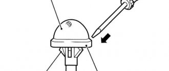
This image will help you set the TDC. Photo: avtodvizhok.ru
- The first step is setting the TDC. This figure must be at least 4 cylinders. It is easy to see by the position of the special slider. When this is done, the crankshaft ratchet is rotated to the mark on the pulley.
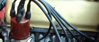
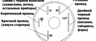
- Old spark plugs and coils with tumblers are completely dismantled. The main thing is to remember the color of the wires that connect to the devices, as well as the order of operation.
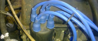
- After this, they proceed to laying new wiring.
- The new high-voltage coil is installed first.
- Then there's Tumblr. It should stand exactly the same as the old one. There are slight differences in this indicator between different models. Only the height of the cylinder block can be different in certain systems. Depending on this, the appropriate length that the drive shaft must have is selected.
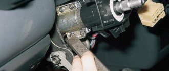
- The next step is attaching the switch. The engine compartment shield is an ideal place to mount this device.
- The candles are screwed in separately. Wires that support high voltage are put on.
- Wiring is connected.
About the features of dual-circuit ignition
Typically this type is installed on engines that operate and are sold in conjunction with carburetors. Thanks to this, it is possible to minimize the disadvantages that the corresponding types of motor have.
It is believed that the transition from 1-circuit ignition to 2-circuit ignition is considered serious progress. In modern conditions, the first version of the archaic system has long been outdated.
Changes can be felt immediately after the system has been installed. But is there any point in installing a new option? To answer this question, you need to understand everything a little deeper.
Find out how a dual-circuit system with one hall sensor works in this video:
Some switches have built-in devices and systems that allow you to monitor peak moments. And monitor the device when the energy ceases to be effective. The switch mode appears automatically in the switch to prevent the coils from getting too hot. For example, in normal mode, approximately 10 A is supplied. When operation is limited, the result is reduced by about half.
The device remains in this position until a special signal is given. There are other rules that are no less important.
- The energy storage time is determined by the amount of current supplied through the coil.
- Voltage itself does not have its own time value. It depends on what voltage the on-board system operates at.
For example, when the engine is running, the on-board network produces an average voltage of 14 volts.
In the average coil, the maximum voltage accumulates in about three milliseconds. Photo: aliexpressin.ru
Everything happens at the moment when the circuit is closed and the coil is fully charged. The time has come to give a signal for sparking. We get the following results after calculations from standard mathematics:
- At engine speeds above 1000 units, 33 sparks occur per second.
- 30 milliseconds in this situation is the time interval from the formation of one spark to the next.
- It takes three milliseconds for the coil to charge. And there is only one spark for the combustion process.
- We get a total cycle of 4 milliseconds. This makes it possible to quickly supply additional charges to the coil.
The coils perform best when the speed level is maintained at up to 6 thousand units. In this case, the device fires approximately 200 times per second. This means the cycle is up to 5 milliseconds. There is enough time for the device to ignite quickly and continue to work as efficiently as possible.
But difficulties can be encountered when operating at 7500 rpm or more.
Proven ignition circuits
The main thing during work is to check the standard diagrams. Or with the option that the user himself chose in this or that case. Only after completing a complete check can you proceed to starting the engine. You must make sure that the position and operation of the parts fully correspond to the diagram.
For greater clarity, you can use this diagram. Photo: ha.d-cd.net
Most of the work in this direction is related to electrical network components. This means that without minimal information in this area, it is better not to start the process at all.
And another version of the 2-circuit ignition circuit.
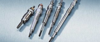
Replacing spark plugs before installing electronic ignition systems
Spark plugs are the last element of the spark generation system in any engine. They work under conditions of high pressure and temperature.
Sparking occurs on them when a high voltage pulse is applied. Therefore, it is not possible to test them, without a test bench, in domestic conditions.
The serviceability of a working spark plug can only be judged visually - by carbon deposits on its tip or presence on the “skirt”. To ensure reliable engine operation, change spark plugs according to the motorcycle operating rules, without expecting them to work forever.
Choose the correct heat rating when purchasing spark plugs. Set the gap in the spark plug electrodes to 0.7-0.8 mm.
We hope that these problems with the spark plugs are not observed and, after purchasing (manufacturing) a non-contact type ignition system and replacing the spark plugs, we begin adjustment work.
Electronic ignition "Saruman"
The Saruman microprocessor ignition system is another way to quickly and without much hassle replace the outdated contact ignition of the Ural. Manufacturers promise the same set of advantages as the previous system. There are two configuration options: with a Hall sensor and with an optical sensor. The second option is somewhat more expensive, but it is usually recommended, since the optical sensor is more accurate and reliable. However, reviews from motorcycle owners are not as good as we would like, mostly complaints are made about the quality of assembly of parts. Another complaint is that the kit does not include an ignition coil.
Setting up and adjusting the ignition on Dnepr and Ural motorcycles.
The procedure for adjustment and tuning is the same for all motorcycle models. Features are associated only with the specifically installed electronic ignition system. General order:
- We install an electronic ignition system on a motorcycle;
- We set the ignition timing by turning the shaft and aligning the stamped arrow on the flywheel with the mark on the engine crankcase;
- We connect the wires according to the manufacturer’s diagram;
- Without turning the shaft, we adjust the position of: module, flow sensors (Hall, optical), modulator;
- We secure the elements of the ignition system.
- We rotate the shaft and control the formation of a spark;
- We adjust the optimal ignition timing after a test run.
When using 92 grade gasoline on motorcycles, we make adjustments from the standard ignition timing adjustment. We put it out a little earlier.
Installing an electronic ignition system will allow trouble-free operation of the motorcycle in any weather and climatic conditions.
Many motorcycle enthusiasts prefer to install electronic ignition on a Ural motorcycle. This is due to a number of technical reasons. Below we will look at the features of this work, as well as the advantages of such ignition.
SZ scheme
The ignition system used on the VAZ 2109 includes the following components:
- Switch;
- Candles;
- Distributor sensor;
- Ignition coils;
- Switch;
- Locking device. It does not allow the starter to turn on until the ignition is completely turned off;
- Locking and anti-theft device;
- Hall Sensor;
- The sensor-distributor roller, which is located horizontally and receives torque from the camshaft;
- System of spontaneous ignition shutdown, which is activated after 2-8 seconds;
- Switched current equalization system, which is required when the network voltage changes within the range of 6-18V;
- The system built into the switch, which regulates the time of energy accumulation in the coil, limits the current strength at low motor operating frequencies.
The ignition system operates with a voltage of up to 26 kV, the spark charge has a duration of 1.6-2.0 milliseconds, and the energy released during this time is 35-50 MJ.
Service
If you do not monitor the state of the system and lose sight of the presence of malfunctions and malfunctions, this can lead to certain consequences. Namely:
- Reduced reliability of the operation of the protective equipment, the occurrence of failures;
- Reduced technical characteristics of the engine, such as acceleration dynamics, maximum speed;
- A sharp increase in the amount of fuel consumed;
- Failure of SZ elements or the entire system.
Before you carry out maintenance on the SZ yourself, take into account several important recommendations.
- Do not touch the ignition coil with your hands while the engine is running. This applies to wires, switch and other components.
- Do not test the SZ for performance using the “spark” method, as this can lead to injuries and costly repairs of the entire vehicle;
- Under no circumstances should you start the engine with a spark gap between the central terminal of the distributor sensor and the high voltage.
Maintenance
Maintenance of this system includes the following operations:
- Cleaning spark plugs from accumulated carbon deposits or replacing elements;
- Checking wires for insulation, quality of contacts and fastening;
- Ignition timing control, timing setting;
- Cleaning the rotor cover and distributor sensor when contamination occurs;
- Cleaning the rotor plate, electrodes of the SZ side terminals;
- Checking the quality of fixation of all system elements on the seats;
- Checking the wire fastenings.
Distributor repair
The ignition system on the domestic VAZ 2109 car is quite complex, although the principle of its operation does not cause serious difficulties even for beginners.
Prevention and repair of the vehicle involves working with the electrical component of the car, so be sure to follow all established safety rules and rely on the recommendations specified in the vehicle’s operating manual.
Mechanical or electronic
Initially, these motorcycles had mechanical ignition. Unlike BSZ, this option has low reliability. The reason is in the mechanical elements of the structure; they wear out over a certain mileage, which leads to regular failures. And you have to adjust the ignition on the Ural motorcycle much more often
The electronic ignition system on a motorcycle does not have such problems. There are practically no interacting elements here. Therefore, the service life is significantly longer. Also, thanks to improved spark formation, there are fewer problems with engine operation. The owner is also relieved of the need to regularly clean the contacts. All this leads to the massive spread of BSZ on this model.
Features of the electronic system
If you prefer to service your motorcycle with your own hands, then this ignition for the Urals will be an ideal option for you. It is much easier to maintain. There is no need to adjust the gaps on the contacts, which significantly reduces the time of service work. Also, the ignition timing does not change during operation.
Also, a huge advantage of this ignition option for a Ural motorcycle is that the spark plugs last longer. Thanks to more efficient spark formation, the load on them is significantly less.
Immediately after installing the new unit, you will notice an increase in engine efficiency. Fuel consumption is reduced and it becomes more responsive on the road. Also important is the absence of problems at low temperatures and wet weather.
Contactless ignition systems
Not so long ago you could only find a homemade device. The reason is the lack of proper supply in stores. Craftsmen in garages remade the contactless unit from other motorcycle models and assembled it from individual parts. This is a rather complex activity that requires skills. Now you can purchase a ready-made kit without any problems.
There are many advantages to using ready-made products. At a minimum, they have been tested in the Urals, which guarantees reliable operation. It is also much easier to install a ready-made unit than to make it yourself. The following sets can be found on the market:
- "SoveK". Under this brand you can find regular contactless ignition, as well as a more advanced microprocessor ignition. The assembly can be supplied with or without a bobbin. Easy to install and practically does not respond to voltage changes;
- "Saruman." Quite an interesting and reliable assembly. There are two sensor options available here; there can be a conventional Hall sensor, or a modern optical one. There is protection against voltage surges, especially high current. To simplify setting the ignition, there is a light indication.
Using ready-made kits is currently the best option.
Wiring diagram for VAZ-2109 carburetor
- Headlight.
- Electric motor for headlight glass cleaning system. An optional part, used mainly on export vehicles.
- Limit switch for powering the engine compartment lamp.
- Klaxon.
- An electric motor drives a fan installed on the radiator of the cooling system.
- Temperature indicator that provides a control signal for the electric drive of the fan impeller.
- Alternator.
- Fluid supply valve for headlight glasses. Used in conjunction with paragraph 2.
- Fluid supply valve for the glass of the fifth door.
- Fluid supply valve to the front glass.
- Spark plugs.
- Hall sensor used to distribute ignition pulses.
- Coil.
- Limit switch for reverse gear lights.
- Fluid temperature meter in the cooling system.
- Starter.
- Accumulator battery.
- A sensor that measures the fluid level in the brake booster.
- Switch that controls the ignition system.
- Sensor for determining the position of the top dead center of the piston of the first cylinder. Installed on some export VAZ 2109 with a diagnostic system. Found only on cars before 1995.
- Diagnostic block. Optional element, installed together with item 20.
- Controller for controlling the solenoid valve installed in the carburetor.
- Starter switch contact block.
- Limit switch on the carburetor.
- Economizer valve.
- Sensor signaling an emergency decrease in oil pressure.
- Washer pump drive.
- Fan impeller motor for ventilation and heating systems.
- Resistance providing additional fan speeds.
- Speed shifter.
- Windshield wiper drive.
- Cigarette lighter.
- Illumination system for levers for adjusting heater operating parameters.
- Socket for additional equipment.
- Lamp for auxiliary lighting of the engine compartment.
- Illumination system for the glove box on the instrument panel.
- Relay and fuse link mounting block.
- Instrument panel light switch.
- Parking brake lamp limit switch.
- Brake lamp limit switch.
- Steering column switch lever block.
- Exterior lamp switch.
- Hazard switch.
- Turn on the rear fog lamp.
- Bimetallic fog lamp fuse.
- Heated glass switch on the fifth door.
- Turn signal repeaters on the front fenders.
- Central interior lighting.
- Individual lampshade.
- Switches for backlight operation on the middle pillars.
- Ignition switching unit.
- Egnition lock.
- “Low” type instrument cluster.
- Choke limit switch on the carburetor.
- Rear lights.
- Fuel level meter in the tank.
- Heated glass.
- Rear wiper drive.
- Two lamps for room illumination.
Wiring diagram VAZ-2109 carburetor - full view:
All carburetor “nines” use the same non-contact ignition system, built on the basis of an electronic switch and a Hall sensor.
The failure of the electronics control unit, which is typical for the Nine, occurs due to the fact that the housing allows water, dust and moisture in the form of condensation to pass through. The factory provided a tiny groove to drain water from the housing, but it constantly gets clogged, the housing fills with water, and the control unit slowly fails.
Selection of candles
The contactless system has certain requirements for candles. If they are faulty or do not fit a specific motor, then you will not get any positive effect from using this system.
Be sure to check the condition of the spark plugs. They should not have soot. It is optimal if the electrode has a sand color. If necessary, replace the spark plugs; when selecting, pay attention to the heat rating. When the spark plugs are in order, the electronic ignition can be installed.
Advantages of dual-circuit ignition
This ignition option has several components:
- Distributor.
- Coil.
- Switch.
There are also additional parts, without which a correct system cannot be created:
- Good wiring to match new ignition.
- Various types of fastenings.
- Spark plugs with appropriate characteristics.
Such a system has its sides, both negative and positive.
Among the advantages:
Installation
Now you can install a new ignition system for the Ural motorcycle. Before starting work, dismantle the old BSZ. Installation is carried out in the following order:
- We install a new coil, here you will need a connection diagram, otherwise problems will arise further;
- We install the ignition module, it should be secured so that it is directed towards the coil.
- The engine rotor is installed in the position at which the ignition is adjusted.
Now you have a contactless ignition system installed, all you have to do is configure it to achieve optimal performance. Please note that setup here is only required once. In fact, you already know how to install the BSZ.
Ignition system of VAZ 2108 Lada Samara
- Repair manuals
- Repair manual for VAZ 2108 (Lada Samara) 1984+.
- Ignition system
9.7.1 Ignition system Elements of the ignition system: 1 — commutator radiator 2 — commutator 3 — ignition coil 4 — ignition distributor Before you begin: disconnect the wire from the “–” terminal of the battery.
9.7.2 Ignition distributor PERFORMANCE ORDER 1. Use a screwdriver to press the spring bracket on the block and disconnect the block with wires from the low-voltage terminal of the ignition distributor. 2. Unscrew the two fastening screws... 3. ...remove the distributor cover, leaving it on the wires. ...
9.7.3 Disassembling the ignition distributor Ignition distributor: 1 - o-ring 2 - clutch 3 - adjusting washers 4 - roller with centrifugal regulator 5 - support plate 6 - dust shield 7 - slider 8 - Hall sensor 9 - lock washer 10 - thrust washer 11 - housing 12 - vacuum corrector ORDER...
9.7.4 Defective ignition distributor PERFORMANCE ORDER 1. Wipe the distributor cover from the outside and inside. Replace a cover with cracks, signs of puncture (very thin cracks), chips or badly worn contacts. The contact ember must move freely inside the lid. 2. If the contact...
9.7.5 Assembling the ignition distributor PERFORMANCE ORDER 1. Lubricate the bushings... 2. ... and the distributor shaft with a thin layer of engine oil. 3. Before installing the clutch, install the slider with the outer contact towards the contact of the first cylinder in the cover. 4. Install the coupling on the shaft so that...
9.7.6 Ignition coil Before you begin: disconnect the wire from the “–” terminal of the battery. PERFORMANCE ORDER 1. Disconnect the high-voltage wire from the ignition coil. 2. Unscrew the two nuts securing the coil bracket (the second nut is located under the battery platform)…
9.7.7 Checking the ignition coil PERFORMANCE ORDER 1. Inspect the coil. If the plastic cover has chips, cracks, signs of overheating or oil leakage, the coil must be replaced. 2. Check the resistance of the primary winding of the coil. To do this, connect an ohmmeter to the low-voltage terminals of the cat...
9.7.8 Testing and Replacing the Switch Warning The switch generates a large amount of heat when operating. In addition, the “ground” of the switch is connected through its heatsink. Therefore, periodically clean the switch radiator from dust and dirt to improve heat transfer. EXECUTION ORDER 1. Disconnect...
9.7.9 Ignition switch (lock) Notes To check the ignition switch, sequentially set the key to the positions at which the circuits indicated in the table should be closed. When the key is turned to position “III”, the anti-theft device should be activated. When turning the key from position “III” to position “0” against...
↓ Comments ↓
1. Description of the car
1.0 1. Description of the vehicle 1.1 Engine compartment 1.2 General data 1.3 Technical characteristics 1.4 Passport data
2. Vehicle operation
2.0 2. Vehicle operation 2.1 Side doors 2.2 Tailgate 2.3 Opening and closing the hood 2.4 Luggage compartment 2.5 Replacing and servicing windshield wiper blades 2.6 Adjusting the front seats 2.7 Controls 2.8 Ventilation and heating of the interior 2.9 Eliminating fogging or frosting of windows 2.10 Seat belts 2.11 Refueling the vehicle 2.12 What you need to have in your car 2.13 Preparing the car for departure 2.14 Checking the wheels 2.15 Checking the level and adding coolant 2.16 Checking the level and adding oil to the lubrication system 2.17 Checking the level and adding fluid to the washer reservoir 2.18 Checking the level and adding oil to the gearbox 2.19 Checking the level and topping up brake fluid 2.20. Starting the engine 2.21 Disconnecting and connecting the battery 2.22 Removing and installing the battery 2.23 Replacing a wheel 2.24 Checking and cleaning the radiator 2.25 Raising the car 2.26 Towing 2.27 Replacing fuses 2.28 Operation during the warranty period 2.29 Running in
3. Vehicle maintenance
3.0 3. Vehicle maintenance 3.1 Checking the tightness of the cooling system 3.2 Checking the tightness of the fuel system 3.3 Replacing the coolant 3.4 Replacing the oil filter and engine oil 3.5 Checking and adjusting the parking brake 3.6 Replacing the air filter filter element 3.7 Checking and adjusting the generator drive belt 3.8 Replacing the belt generator drive 3.9 Cleaning and flushing parts of the crankcase ventilation system 3.11 Checking and replacing spark plugs 3.12 Replacing the fine filter 3.13 Checking the air filter thermostat 3.14 Changing the oil in the gearbox 3.15 Checking the front wheel drive and gear shift rod joint 3.16 Checking the condition of the front and rear suspension elements, their rubber-metal hinges, bushings and cushions 3.17 Checking the steering wheel play 3.18 Checking the condition of the steering rods, their protective caps, protective covers for the steering mechanism 3.19 Replacing the brake fluid 3.20 Checking and replacing the front wheel brake pads 3.21 Checking and replacing the rear wheel brake pads 3.22 Bleeding the brake system 3.23 Checking the efficiency of the brake system 3.24 Checking the tightness of the brake system 3.25 Checking the operation of the vacuum booster 3.26 Checking the pressure regulator 3.27 Checking and adjusting the free play of the brake pedal 3.28 Checking the exhaust system 3.29 Servicing the battery 3.30 Checking the operation of electrical components 3.31 Adjusting the headlights 3.32. Replacing lamps
4.Car care
4.0 4. Car care 4.1 Care and restoration of body paint 4.2 Body lubrication 4.3 Cleaning drainage holes 4.4. Car storage 4.5 Preparing for winter use 4.6 Tips for starting the engine in severe frost 4.7 What is useful to buy for winter 4.8 Tips for winter use of the car
5. Problems along the way
5.0 5. Malfunctions along the way 5.1. Malfunctions of the injection system 5.2. Checking electrical equipment 5.3 Extraneous knocking noises appeared 5.4 Vibration and shock on the steering wheel 5.5. Brake problems 5.6 Wheel puncture
6. Chassis
6.0 6. Chassis 6.1. Telescopic front suspension strut. Disassembly 6.2. Rear suspension
7. Steering
7.0 7. Steering 7.1 Steering column 7.2 Steering mechanism 7.3 Replacing steering rods
8. Brake system
8.0 8. Brake system 8.1 Rear wheel brake 8.2 Wheel cylinder 8.3 Brake drive
9. Electrical equipment
9.0 Electrical equipment 9.1. Generator 9.2. Starter 9.3. Lighting and light signaling 9.4. Heater 9.5. Windshield wipers 9.6 GENERAL INFORMATION 9.7. Ignition system 9.8 Instrument panel (high) 9.9 Instrument panel (low)
10. Body
10.0 10. Body 10.1 Replacing the rear buffer 10.2 Replacing the radiator lining 10.3 Replacing the front fender 10.4 Removing and installing the hood 10.5 Adjusting the hood 10.6 Adjusting the hood latch 10.7 Side door 10.8 Tailgate 10.9 Front seat 10.10 Rear seat 10.1 1 Seat belts
11. Engine and its systems
11.0 11. Engine and its systems 11.1 Adjusting the clearances in the valve drive 11.2. Power supply system 11.3. Removing the oil pump 11.4. Radiator and fan with casing 11.5. Exhaust system 11.6 Complete disassembly of the engine 11.7 Cylinder block. Inspection, troubleshooting and repair 11.8 Piston with connecting rod. Disassembly, troubleshooting and assembly 11.9. Cylinder head 11.10 Engine assembly 11.11 Replacing engine oil and oil filter 11.12 Replacing and adjusting the tension of the generator drive belt 11.13 Replacing and adjusting the tension of the camshaft drive belt 11.14. Carburetor adjustment
12. Transmission
12.0 12. Transmission 12.1 Removing the gearbox 12.2 Installing the gearbox 12.3 Adjusting the clutch drive 12.4 Disassembling the gearbox 12.5 Inspection and troubleshooting of gearbox parts 12.6. Secondary shaft of the gearbox 12.7 Primary shaft of the gearbox 12.8. Differential 12.9 Synchronizer 12.10 Gear shift mechanism 12.11 Gearbox assembly 12.12 Gear shift lever 12.13 Changing the oil in the gearbox 12.14 Replacing the clutch 12.15. Clutch drive 12.16. Front wheel drive
13. Basic data for adjustments and control
13.0 1. Basic data for adjustments and control 13.1 2. Fuels and lubricants and operating fluids 13.2 3. Tightening torques of threaded connections 13.3 4. Service book 13.4 5. Electrical diagram of the VAZ-2108
Settings
Now we adjust the ignition timing. We install the motor in accordance with the marks, connect all the wires. Next you need to adjust the position of the sensors. Next, we attach all the elements and check for sparking. If everything is fine, then you should drive 10-20 kilometers and check the set angle again.
If necessary, adjustments are made, but if everything is done correctly, this will not be necessary. Knowing how to do contactless ignition on your motorcycle, you will not wonder how much this work costs in a workshop.