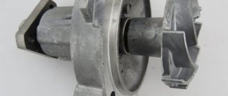
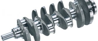
What is death for a foreigner is a godsend for a Russian. In any repair there are certain standards that many adhere to, but for those who do a lot of things with their own hands, these standards are not written. The whole point is the high cost of meeting these standards. I’ll show you how you can adjust the camshaft cushions of a ZMZ 406 engine head from another head. Although, according to the rules of the standards, it is impossible to place camshaft cushions from one head to another, since they will either clamp the camshaft or the camshaft will dangle in them. This method can be applied to any cylinder head where there are camshaft cushions, for example in VAZ engines.
So I had to show off a little by adjusting the 406 head cushions to another 406 engine head. The owner of the Gazelle brought it in and asked to replace the cylinder head with another one, which he bought at a disassembly site for pennies but without camshaft cushions. But for us this is not a problem, everything can be adjusted, you just need to know how to do it. In the original head of the 406 engine there was a microcrack due to which gases were leaking into the cooling system.
Connecting high-voltage wires ZMZ 405, ZMZ 406
ZMZ carburetor and Euro-2 engines are equipped with a DIS (Double Ignition System) ignition system.
The DIS system uses ignition coils with two high-voltage wires. Each coil operates a corresponding pair of cylinders.
The first coil works with 1 and 4 cylinders, the second coil works with 2 and 3 cylinders.
How to connect the ignition coils?
The ignition coil of cylinders 1 and 4 is located closer to the intake manifold, the coil of cylinders 2 and 3 is closer to the exhaust manifold.
Low-voltage coil wires must be connected to the coil in pairs. The pair of wires for coil 1-4 is slightly shorter than the pair of wires for coil 2-3.
Within the pair, it does not matter which contact is connected to which wire - the coils are non-polar. Also, within the pair, it does not matter which high-voltage wire goes to which cylinder.
Let's look at an example (see photo)
Coil 1 control (cylinders 1 and 4) – green and yellow wires. This pair connects strictly to the coil of cylinders 1 and 4!
Low voltage circuit - polarity is not important - can be connected:
Option 1: The top coil contact is yellow, the bottom contact is green.
Option 2: The top coil contact is green, the bottom contact is yellow.
High voltage outputs – polarity is not important – can be connected:
Option 1: Top outlet for cylinder 1, bottom outlet for cylinder 4.
Option 2: Top outlet for cylinder 4, bottom outlet for cylinder 1.
Coil 2 control (cylinders 2 and 3) – blue and yellow wires. This pair is connected strictly to the coil of cylinders 2 and 3! Further - similar to pair 1-4 - the polarity within the pair is not important.
The determining factor when connecting pairs of low-voltage and high-voltage wires to the corresponding ignition coil is the correctness of their routing. The wires should not be too tight, bent too much, and should not rub against fixed parts of the engine or other wires.
Another article about high-voltage wires ZMZ 405, 406 - read so as not to repeat this mistake.
The ZMZ-406 engine is equipped with a microprocessor ignition system, which consists of a control unit for fuel injection and ignition systems, two ignition coils of types 30.3705 or 301.3705, spark plugs, high-voltage and low-voltage wires.
The control unit is installed in the car interior on the right side under the instrument panel, behind the body side upholstery.
The ignition coils are installed on the cylinder head cover.
The control unit receives signals from sensors installed on the engine and, based on this, adjusts the ignition timing, which allows for optimal power, economic and toxicity indicators.
Electrical diagram of an integrated microprocessor engine control system (KMSUD)
Ignition coil
1. Disconnect the wire from the negative terminal of the battery.
2. Disconnect 4 blocks 1 of low-voltage wires and high-voltage wires 5 from the coil.
Unscrew bolts 2, remove bar 3 and coil 4.
3. Remove the second coil in the same way.
Examination
1. Coils 30.3705 and 301.3705 are checked with a spark plug diagnostician 1AP975000 on a car.
To do this, disconnect the high-voltage wires from the coil and connect the diagnostician instead.
Then crank the engine with the starter, while a spark should jump in the diagnostic spark gap in time with the operation of the cylinders.
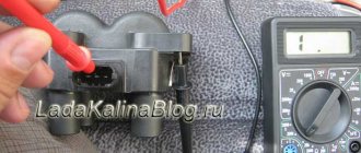
2. Check the resistance of the primary winding of the ignition coil by connecting an ohmmeter between the low voltage terminals.
The ohmmeter should show a resistance of 0.025–0.03 ohms.
Then check the resistance of the secondary winding by connecting an ohmmeter between the high voltage terminals of the ignition coil.
The ohmmeter should show a resistance of 4000–5000 ohms.
If the measured parameters differ from those specified, the coil must be replaced.
Install the ignition coil in the reverse order of removal.
How is a spark formed at a spark plug? According to the theory of electrical engineering, a voltage of 3000-4000 volts is required to break down 1 mm of ideal air space. In the interior of the cylinder block, the conditions are more stringent, but in any case, an uninterrupted supply of electricity is important for spark plugs. Thousands of volts are generated by the coils or ignition module; their description deserves a separate article.
To eliminate the weak link, some manufacturers install bobbins directly on the spark plugs. This makes the system more reliable and, accordingly, more expensive. We will look at the classic circuit: coil - high-voltage ignition wires - spark plug.
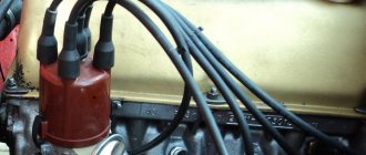
Car enthusiasts call ignition wires differently: spark plug, bobbin wire, armored cable. We are talking about the same product.
Powertrain capabilities
Owners of the Gazelle-405 car are impressed by the fuel-injector engine, especially in terms of fuel consumption. It ranges from 8 liters on the highway to 13 in the combined cycle when driving around the city. Oil is also used sparingly: approximately 100 grams per thousand kilometers. In a single-point system, the manifold is equipped with only one injector for all cylinders. In a distributed block, each of them has its own collector. And with direct injection, fuel is supplied directly to the cylinders, just like a diesel engine.
Injection cars are more economical, as precise dosing occurs. In addition, the environmental friendliness of the exhaust gases released into the environment complies with the Euro 3 standard, and the power indicator increases by 10%.
This power unit is adapted to domestic climatic conditions. It tolerates heat, extreme cold and sudden temperature fluctuations well. The power plant functions clearly and reliably in the most severe and difficult climatic zones. It starts without problems in severe frost.
What are the requirements for spark plug wires?
Any conductor has a certain service life. If the cables are laid in a bundle, have an outer braid and are fixed permanently (protected from vibration loads), the service life is equal to the life expectancy of the car. Another thing is the high-voltage ignition coil wire. It is located in the epicenter of unfavorable conditions: vibration, high temperature (as well as changes in winter), gasoline vapors, therefore high demands are placed on the quality of insulation of high-voltage wires and the core:
- The conductors are exclusively copper (as is known, this material has the lowest resistance), but the protective layer can be silicone or rubber. Other insulation materials, although they have good protection, are not soft enough. Another requirement for high-voltage wires is elasticity. Otherwise, the surface will simply crack due to constant vibration;
- Shell thickness is a compromise. If a breakdown of high-voltage wires occurs, a spark will form between the central core and the motor housing. The voltage will not reach the spark plug, but the presence of a sparking conductor in the engine compartment, to put it mildly, is not useful for the car. The other side of the coin is that a wire that is too thick is inconvenient to install, it is inelastic, which makes installation and maintenance difficult;
- The length of high-voltage wires is another headache for the manufacturer. From Ohm's law it is known: the shorter the conductor, the less losses for electric current. In a car, it is not so easy to place all the interacting components next to each other. Mounting the ignition coil above the spark plug wells is good for electricians, but bad for builders. In addition, it is desirable that the cables be of similar length, so the connection diagram for high-voltage wires is carefully calculated, and replacing the cables with universal ones means disrupting the operation of the entire ignition system on the car.
Ignition coil ZMZ 409, 405, installation
Individual ignition coils are usually located in deep “wells”. Considering that they are closed from moisture from above, with a rubber hat, the temperature inside this well is quite high. Result: sticking of the rubber “skirt” of the coil to the spark plug insulator, sometimes just tightly. Sometimes the dismantling process ends with the rubber casing breaking. There were cases when, when removing the coil, I realized that it was impossible to do without surgery and simply took a receipt from clients stating that “the spare part may break.” To avoid this passage, I recommend using high-temperature dielectric grease during installation. There are many manufacturers of this lubricant. Personally, I prefer to work with German and American chemistry. Both of them have gone quite far from the rest in these areas. I have been using Permatex (USA) lubricant for many years. The tube looks very small, but if used correctly, it is enough to mount coils on several engines. Electronics engineers shared links to analogues of these lubricants, which are sold in “electronic components” stores. But unfortunately, I did not find data on the operating temperatures of lubricants. And this is a very important characteristic for our operating conditions.
High-voltage wire tip - what is it for?
Connection in the traditional way is not possible. The tips of the candle should be easily removable, but provide reliable contact. As a rule, the caps are made of a solid dielectric, although there are exceptions. Rubber adheres better to the walls of the spark plug well and ensures tightness. However, this material is subject to wear and tear. Plastic dielectric is more durable, but moisture can condense underneath it. Which material to choose is decided by the manufacturer depending on the design of the cylinder head.
There is one wire coming from the ignition coil; distribution to the spark plugs occurs on the distributor. Depending on the engine design, the four-cylinder version has up to ten tips. Just like the main wires, caps can cause breakdown or loss of contact. Water gets under them, the material cracks, and a spark “pierces” the spark plug insulator.
Gas distribution system.
In the 406th modification, the engine looks like this: four valves are installed on each of the two exhaust and two intake cylinders, the right camshaft (front view) drives the exhaust, and the left camshaft drives the intake. Hydraulic valve drive clearance compensators from the camshaft cams eliminate the need for maintenance and adjustment. The camshafts are driven from the crankshaft by two bushing chains.
View of the correct assembly at TDC of the compression stroke with the piston position of the first cylinder of the camshaft drive:
1. The protrusion on the chain cover (M1) must coincide with the mark on the crankshaft sprocket (2), the horizontal marks (9) on the camshaft sprockets (10, 12) must coincide with the upper plane of the cylinder head.
2. The alignment mark (M2) on the cylinder block must correspond to the mark on the intermediate shaft sprocket.
The center of the twentieth tooth of the synchronization disk (3) must be located, at this position of the shafts, strictly opposite the center of the crankshaft position sensor core (4). The synchronization disk (1) is a gear on which there are 58 cavities located at a distance of 6 degrees from each other, two of which are missing for synchronization. The two missing cavities are the starting point for the tooth numbers (15), and the numbering proceeds in a reverse clockwise direction. However, adjusting the gas distribution system did not lead to the return of the engine's former power.
Now let's get down to diagnosing the ignition system. Control of the forced idle economizer valve in the sixteen-valve ZMZ-4063 carburetor engine and ignition is provided by the MIKAS 5.4 microprocessor system. This system, which allows, depending on operating conditions and engine operation, to implement the most optimal SOP, it consists of wires with connectors, a control unit, a set of actuators and sensors. High specific engine readings without fear of over-ignition and detonation are ensured through effective identification of the detonation combustion control unit of each cylinder and the knock sensor. If the sensors are damaged, the unit instantly implements emergency control mode. The crankshaft position sensor is an exception, since the engine cannot function without it.
Electronic control unit (ECU) Mikas 5.4
A DBP is installed on the engine panel of the vehicle - an absolute air pressure sensor on the intake manifold (Bosch model 0261230004), and is connected to the throttle body in the engine intake manifold. The amount of air that enters the engine cylinders is calculated by the control unit based on the measured value. This sensor looks like an electronic remote integrated device with a working chamber made of silicon and special powder, which has an exemplary pressure inside. The conductivity of sensitive semiconductor elements located inside the working chamber varies directly depending on its mechanical location. The sensor is powered by a stabilized voltage of 5 V, and the output voltage is 0.4...4.65 V and linearly depends on the measured pressure, ranging from 0.2 to 1.05 atmospheres and is connected using a three-pin plug to the wiring harness. A change in the balance of the strain gauge bridge is caused by a displacement of the membrane (i.e., the working chamber), since the resistors are connected in a bridge circuit. An electronic signal processing circuit, located on the same board as the sensing element, is connected to these resistors.
Absolute pressure sensor (MAP)
To determine the engine temperature, the car is equipped with a DTohl (coolant temperature sensor) models 19.328 or 40.5226, manufactured in Russia. The unit controls the forced-idle economizer valve and also adjusts the ECO valve in accordance with the measured temperature value. The control system consists of an ignition coil, a forced-idle economizer solenoid valve and a knock sensor. DTohl, installed on the outer shell of the cooling system thermostat, is connected to the harness using a two-pin connector.
Coolant temperature sensor (DTohl)
Opposite the crown of the crankshaft pulley toothed disk, in the boss of the gas distribution mechanism chain cover, an induction-type crankshaft position sensor (DPKV) model 23.3847 made in Russia, or model 0261210113 from the German company Bosch, is installed, which is connected by a flexible cable to a three-pin electrical plug. This sensor has the form of a coil with a magnetic core, with a winding resistance of 880 to 900 Ohms. To ensure optimal operation of the control system, a gap of 0.5 to 1 millimeter is required between the teeth of the disk and the sensor. In order to avoid damage to the sensor cable by rotating parts of the generator or engine, it must be secured as securely as possible, since a malfunction of the DPKV leads to the engine stopping.
The procedure for connecting high-voltage wires
If the cables are the same length, they can be easily mixed up. The output device must have cylinder markings. An incorrect connection will cause the spark sequence to be disrupted. In the best case, tripping or detonation will occur, in the worst case, the engine simply will not work. In order to follow the order of connecting high-voltage wires, it is recommended to photograph the process before dismantling them, or mark the caps in accordance with the cylinder numbers.
If the distributor (ignition module) is located at the end of the cylinder block, the length will be different, and replacing high-voltage wires will not cause difficulties.
Checking for correct installation
If the order is followed without errors in the ignition of the 402 engine, then the next task will be to check the power plant while the car is moving:
- We go out onto the highway and, when driving 60 km/h, turn on fourth gear. We are accelerating. The appearance of short-term detonation knocks indicates that the ignition is installed correctly.
- Prolonged detonation knocks are confirmation of incorrect setting of the advance angle.
In this case, you should reduce it with an octane corrector, moving it to one notch. If detonation cannot be heard at all, then the advanced ignition angle of the fuel mixture should be increased. And check again for correct installation by accelerating the car to 60 km/h and shifting to fourth gear.
Malfunction of high-voltage wires: symptoms and consequences
The general symptoms are similar to problems with spark plugs (unless the injector is to blame for the failure), so before checking the high-voltage wires, make sure that the remaining engine components are in good working order.
- Problems with starting - the spark plugs do not receive enough voltage. This could be a broken wire or corrosion of the tip contacts. The malfunction is typical for an engine that is not warmed up;
- The engine “shoots” at start; If it starts, it runs unevenly, with increased vibrations. The order of connecting high-voltage wires is violated;
- Ragged operation at idle. The connection with the candle is lost due to vibration;
- Violation of CO emission standards. The problem is accompanied by periodic tripping of the motor. One of the cylinders misfires and the fuel does not burn completely;
- Interference on the multimedia system: the character changes when the crankshaft speed changes. In the slang of car enthusiasts, high-voltage car wires are “sewn to ground.” Multiple discharges on the motor housing create “thunderstorm” interference;
- Smell of ozone under the hood. The reason is the same as in the previous paragraph: high-voltage wires penetrate the housing.
Operation depends on correct ignition
Automotive power units work productively if the ignition system is adjusted to 402 fuel-air mixture. The carburetor forms the fuel composition and supplies the prepared mixture to the engine cylinders.
At the moment of the highest position of the pistons, the spark plugs generate a spark that ignites the fuel mixture in the combustion chamber. A mini explosion of fuel with the resulting gases presses on the pistons, turning their forward motion into torque of the crankshaft.
The algorithm for igniting the mixture highlights one important point in the sequence of events. Will the engine work fully if the mixture is ignited at the beginning of the piston lifting or lowering? The correct answer is no.
Any internal combustion engine works like a clock, provided the fuel is properly ignited. The power of the power plant increases, approaching the established standards. To do this, it is necessary to fix the correct spatial position of the distributor, which alternately closes the electrical circuit from the high voltage coil to the car spark plugs.
Checking high-voltage ignition wires using improvised means
If your car is equipped with an OBD port, you can localize the fault to at least the cylinder number. The most primitive scanner (such as ELM 327) will show misfire or lack of ignition. With any method of identifying a problem area, it is better to test the wires in the removed state. For a complete test, you will need a voltage multiplier and a megohmmeter (to check the insulation). Wires are connected to the high voltage source and laboratory tests are carried out. As a rule, there is no such equipment in the garage, so we will use a multimeter.
The test begins with a visual inspection. There should be no cracks on the insulation, no black points of spark breakdown, the cable should bend with the same force in any place. Tips without oxides or breaks. The caps are intact, with the same thickness of the skirt.
Then we measure the resistance of the high-voltage ignition wires. On all armored cables it should be approximately the same - within 2 kOhm - 10 kOhm. Exactly what value depends on the manufacturer. The denomination can be found in the product passport. It is impossible to replace high-voltage wires with non-standard ones (from another car), their resistance is calculated according to the capabilities of the ignition coil. Faulty ones must be rejected: repair of high-voltage wires inside the insulation is impossible.
Important! Connecting the multimeter probes must have good contact, otherwise you may introduce a high error in the measurement.
Work principles.
Using the signal from the crankshaft position sensor, the control unit calculates the rotation speed, and the amount of cyclic air filling of each of the four engine cylinders is determined by measuring the absolute pressure. The ignition timing angle, which depends on the cyclic filling and rotation speed, and corresponding to the engine operating frequency, is stored in the unit’s memory device. These angular values have an additional adjustment depending on the coolant temperature. Providing good traction properties under these conditions is achieved by increasing the angular values of the ignition timing in a cold engine. Also, if a detonation fire is detected due to certain factors, such as changes in environmental conditions or the use of low-octane fuel, the control unit will adjust the SOP. If the absolute pressure or ambient temperature sensors are damaged, the control unit activates emergency programs and turns on diagnostic lamps. Reduced power, deterioration of dynamic properties, increased fuel consumption - all these are the results of operating a car engine with these malfunctions. In addition, in addition to ignition control, the functions of the unit include control of the economizer solenoid valve for forced idle speed, which, when the vehicle is braking by the engine, ensures that the fuel supply is turned off. The crankshaft rotation value to turn off the fuel supply is 1860 rpm, and to resume the supply - 1560 rpm.
Checking high-voltage ignition wires without removing them from the car
This is a primitive but quite effective method. The simplest option is to install a known-good cable and compare the operation of the engine. If the location of the high-voltage wires allows, you can swap them (along with the connector on the distributor), and again read the errors with the scanner. It will indicate a different cylinder number.
Putting a dielectric glove on your hand, you can remove the tips from the spark plugs one by one while the engine is running. When you reach the problem cylinder, the nature of the work will not change.
Definition of breakdown “by eye”. In the dark you can see how the spark “sews” onto the body of the internal combustion engine. You can connect a thick wire to ground and run the bare end along the insulation. You will see the weak point immediately - a spark will strike.
Despite a whole bunch of breakdowns that armored wires can cause, their solution is no more difficult than replacing plugs in a home electrical panel. If a faulty one was identified, a new one was installed. If there is a problem, how to change high-voltage wires on the highway or in an open field (far from stores), remember that the cables do not break suddenly; regular diagnostics will help you not to be caught by surprise.
How to set the ignition on a Gazelle
How to properly install the ignition on a 402 engine
GAZ Community
It's almost worth touching VOLGA. The MH is set at the midpoint (for the 92nd or in the center between 3 and 2 for the 80th). If there is BSZ, the magnet risk must be adjusted by the arrow on the coil sensor body (rotate the magnet to the right until it stops). Before installing the MOH, set the octane adjuster medium mark opposite the arrow of the washer under the mounting bolt, adjust it by unscrewing the BACK bolt from the rear of the housing (use the octane adjuster bolt if the lower bolt is not adjusted). The final ultrasonic leveling must be done on the road (at 40 km/h, sharply push the gas to the floor. A short detonation will appear. The knock can reach 65-70 km/h). fortune
Dude helps from time to time Message: 532 Date of registration: September 05, 2013, 16:54 From: Ryazan Contact information:
There is a factory abstract, it is not clear.
This is the table for the 402 engine.
1. Turn off the vacuum box with tube.
2. Specific check.
600 grams per minute 5 grams of removal, this is the middle second mark on the crankshaft pulley. We look at the gate. 1st TDK character, 3rd. 12 gr.
Then we place the assistant in the cockpit, he accelerates the speed to 850 with approximately the gas pedal. We look at the table, it should be 10 grams. Between the second and third marks of the crankshaft pulley, there are marks on the markings here and there.
Then the assistant increases the engine speed to approximately 1250. The gate should show 12-14 grams, i.e. 3rd mark on pulley b/c.
Then 1750 rpm = 15-18 deg, from the third mark you need to add a distance equal to the length between the first and second marker marks, i.e. 125 = 17 grams removed.
There is actually another method that I will look at now.
Last edited by Dude on September 14, 2013 01:26 pm, all edited 1 time.
Dude helps from time to time Message: 532 Date of registration: September 05, 2013, 16:54 From: Ryazan Contact information:
The procedure for connecting armored wires ZMZ 406
The ZMZ-406 engine is equipped with a microprocessor ignition system, which consists of a control unit for fuel injection and ignition systems, two ignition coils of types 30.3705 or 301.3705, spark plugs, high-voltage and low-voltage wires.
The control unit is installed in the car interior on the right side under the instrument panel, behind the body side upholstery.
The ignition coils are installed on the cylinder head cover.
The control unit receives signals from sensors installed on the engine and, based on this, adjusts the ignition timing, which allows for optimal power, economic and toxicity indicators.
Electrical diagram of an integrated microprocessor engine control system (KMSUD)
Ignition coil
1. Disconnect the wire from the negative terminal of the battery.
2. Disconnect 4 blocks 1 of low-voltage wires and high-voltage wires 5 from the coil.
Unscrew bolts 2, remove bar 3 and coil 4.
3. Remove the second coil in the same way.
Examination
1. Coils 30.3705 and 301.3705 are checked with a spark plug diagnostician 1AP975000 on a car.
To do this, disconnect the high-voltage wires from the coil and connect the diagnostician instead.
Then crank the engine with the starter, while a spark should jump in the diagnostic spark gap in time with the operation of the cylinders.
2. Check the resistance of the primary winding of the ignition coil by connecting an ohmmeter between the low voltage terminals.
The ohmmeter should show a resistance of 0.025–0.03 ohms.
Then check the resistance of the secondary winding by connecting an ohmmeter between the high voltage terminals of the ignition coil.
The ohmmeter should show a resistance of 4000–5000 ohms.
If the measured parameters differ from those specified, the coil must be replaced.
Install the ignition coil in the reverse order of removal.
Website for a gardener. Agrochemicals, fertilizers. Garden equipment
The piston of the 1st cylinder is set to the top dead center (TDC) position of the compression stroke so that when carrying out work related to removing the timing chains, the valve timing is not disturbed.
If the valve timing is incorrect, the engine will not operate normally. 1. Remove plug 1 of the oil filler neck. Remove the 2 spark plug tips with 3 high voltage wire seals and wires. Disconnect hose 5 and tube 7 for crankcase ventilation from the fittings on cover 6 of the cylinder head. Unscrew the eight bolts 4 and remove the cylinder head cover 6 with the cover gasket.
2.
Unscrew the four bolts 1 and remove the front cover 2 of the cylinder head, being careful not to damage the gasket. Unscrew bolts 3 and remove plastic chain guide 4. 3. Set the piston of the 1st cylinder to the top dead center (TDC) of the compression stroke. To do this, turn the crankshaft by ratchet 1 so that mark 2 on the crankshaft pulley coincides with protrusion 3 on the cover. Wherein. 4. . marks 1 on the camshaft sprockets should be located horizontally at the level of the upper plane of the cylinder head and directed in opposite directions. After installing the piston of the 1st cylinder in the i.m.t. Do not turn the camshafts, crankshaft and intermediate shaft.
5. If the marks on the crankshaft gears and on the camshaft gears do not match, it means that the valve timing is incorrect (the piston of the first cylinder is not installed at TDC).
The Gazelle-405 car, whose engine-injector uses an injection system that allows efficient consumption and distribution of the fuel mixture throughout the system, is used in cargo and passenger transportation. The design of the power unit differs from its predecessor in the presence of 16 valves. This motor belongs to the ZMZ series produced by the Zavolzhsky plant.
Connecting high-voltage wires ZMZ 405, ZMZ 406
ZMZ carburetor and Euro-2 engines are equipped with a DIS (Double Ignition System) ignition system.
The DIS system uses ignition coils with two high-voltage wires. Each coil operates a corresponding pair of cylinders.
The first coil works with 1 and 4 cylinders, the second coil works with 2 and 3 cylinders.
How to connect the ignition coils?
The ignition coil of cylinders 1 and 4 is located closer to the intake manifold, the coil of cylinders 2 and 3 is closer to the exhaust manifold.
Low-voltage coil wires must be connected to the coil in pairs. The pair of wires for coil 1-4 is slightly shorter than the pair of wires for coil 2-3.
Within the pair, it does not matter which contact is connected to which wire - the coils are non-polar. Also, within the pair, it does not matter which high-voltage wire goes to which cylinder.
Let's look at an example (see photo)
Coil 1 control (cylinders 1 and 4) – green and yellow wires. This pair connects strictly to the coil of cylinders 1 and 4!
Low voltage circuit - polarity is not important - can be connected:
Option 1: The top coil contact is yellow, the bottom contact is green.
Option 2: The top coil contact is green, the bottom contact is yellow.
High voltage outputs – polarity is not important – can be connected:
Option 1: Top outlet for cylinder 1, bottom outlet for cylinder 4.
Option 2: Top outlet for cylinder 4, bottom outlet for cylinder 1.
Coil 2 control (cylinders 2 and 3) – blue and yellow wires. This pair is connected strictly to the coil of cylinders 2 and 3! Further - similar to pair 1-4 - the polarity within the pair is not important.
WHICH GDP IS BETTER TO CHOOSE?
When choosing a GDP, two key factors must be taken into account - their resistance and breakdown voltage. The lower the resistance, the better the electrical impulse will be transmitted, and the magnitude of the maximum breakdown voltage determines how resistant the high-voltage wires on the VAZ 2114 will be to breakdowns.
The resistance value of products from different manufacturers differs from each other. As an example, we give you the resistance of the most popular types of GDP:
| Manufacturer | Resistance on cylinder No. 1 (kOhm) | Resistance on cylinder No. 2 | Resistance on cylinder No. 3 | Resistance on cylinder No. 4 | Breakdown voltage (kV) |
| Tesla | 3.27 | 4.16 | 5.02 | 6.26 | 50 |
| Cezar | 3.1 | 3.53 | 4.23 | 5.34 | 50 |
| Finwhale | 1.95 | 2.18 | 2.6 | 3.42 | 50 |
| Ween | 6.17 | 6.57 | 7.52 | 9.89 | 35 |
| Slon | 4.24 | 4.74 | 5.19 | 7.6 | 50 |
The products of the Czech company Tesla receive the largest number of positive reviews from the owners of the fourteenth. Their wires have optimal resistance and high breakdown voltage, and at the same time they are truly made to last - they do not tan or crack.
The cost of the Tesla GDP set is about 500 rubles, Cezar – 450 rubles, Ween – 270 rubles, Finwhale – 600 rubles, Slon – 500 rubles.
CONNECTION FEATURES
The order of connecting high-voltage wires must be strictly sequential, since each cylinder of the engine corresponds to a specific socket on the ignition module. Considering that there is a numbering of the sockets on the ignition module body, the risk of confusing anything is minimal.
The procedure for connecting high-voltage wires of the VAZ 2114 injection type depends on the year of manufacture of your car. Fourteeners before 2004 had 4-pin ignition modules installed, and cars after 2004 had 3-pin coils.
The connection diagram for VAZ 2114 high-voltage wires to the ignition module (until 2004) is as follows:
Connection diagram for VAZ-2114 with ignition coils (after 2004):
In the pictures you can see the numbers of the landing slots. Each number must have a corresponding cylinder connected to it (cylinder numbering is counted from left to right).
To correctly install high-voltage wires on the VAZ 2114, follow the following algorithm of actions:
- Turn off the ignition. Open the hood and remove the power terminals from the battery;
- We remove the old GDPs from the mounting sockets on the module and cylinders;
- We remember the location of the high-voltage wires of the VAZ 2114 and connect new GDPs according to the diagram. Before replacing, it would not be amiss to draw this very diagram by hand on paper so as not to confuse anything;
- We connect power to the battery and, to check whether we did everything correctly, start the engine.
When installing the wiring, do not try to connect individual air intakes to each other with plastic clamps; to do this, you must use the comb holder that comes with them. A thin clamp can easily wear through the insulating coating. Also make sure that the GDP does not bend.
Connecting armored wires on VAZ 2115 and 2113 is carried out in a similar way.
VESKO-TRANS.RU
AutoNews / Reviews / Tests
- Home
- Auto garage
- How to set the ignition on a Gazelle 405 Engine
How to set the ignition on a Gazelle 405 Engine
Adjusting and installing the ignition ZMZ 402: secrets and tips
engine is one of the products of the Russian auto industry, widely used in the automotive industry. These power units were equipped with certain models of Volga, UAZ, and Gazelle cars. To ensure normal engine performance, the ignition
. In this article we will tell you how to install a distributor on a 402 engine and what should be taken into account when performing the task.
HOW OFTEN SHOULD I CHANGE GDP?
According to the recommendations of Avto-VAZ, replacement of high-voltage wires of the VAZ 2114 should be done every 30 thousand kilometers. In practice, motorists rarely comply with these replacement deadlines, since if the wires do not have any mechanical damage, they can travel about 100-150 thousand km.
When the service life is exceeded, the internal resistance of the GDP increases, which negatively affects the transmission of the electrical impulse. This leads to problems with ignition and acceleration dynamics, since when the supply of current to the spark plugs is delayed, the normal engine operating cycle is disrupted.
Change the wires every 25-30 thousand km and everything will be fine
OPERATIONAL CHECK
To accurately determine whether it is time to change the high-voltage wires of the VAZ, you need to check their performance with a multimeter.
This operation will take you no more than 15 minutes:
- Turn off the ignition;
- We remove the wires: disconnect the first end from the ignition module, the second from the cylinder;
- We switch the tester to ohmmeter mode and connect the multimeter probes to the wire contacts.
If the high-voltage wires on the VAZ 2114 are in normal technical condition, the multimeter will show a resistance within the value indicated on the wire insulation; if the readings are different, the armored wires on the VAZ 2114 need to be replaced. The process must be repeated on each wire in turn.
If the test shows disappointing results, there is a possibility that the problem of increased resistance lies in oxidized contacts. In this case, you can try to revive the VVP by wiping the contacts with VD-40 or carburetor cleaning fluid.
Also, the cause of problems with ignition can be a breakdown of the GDP. You can determine it visually in the dark - take a flashlight and open the hood of the fourteenth, find and inspect the armored wires, if you notice a slight spark on the insulation - the air intakes are broken and need to be replaced.
Burn clearly!
BURN CLEARLY!
DIAGNOSTICS: IGNITION SYSTEM ZMZ-406
You probably know that for the engine to operate, it is necessary to ensure not only that the cylinders are well filled with a mixture of air and fuel, but also that this mixture is properly ignited. While understanding the starting conditions of the ZMZ-406 engine, in previous issues of the magazine we have already checked the electrical circuits of the fuel pump and injectors, measured the fuel pressure, and made sure that it is properly supplied to the cylinders. This means that the engine’s failure to start is most likely due to problems with the ignition. Which ones exactly?
In order for the controller to send control commands to the injectors and ignition coils, it itself must receive signals from the crankshaft position sensor. We were already convinced of the serviceability of this sensor when we checked whether the injector was working (photo 1). If this is the case, then it makes sense to immediately evaluate the performance of the high-voltage part of the ignition system - this is the simplest thing.
Having taken out the spark plug tip of one of the cylinders, insert a probe into it and connect it with a clamp to the valve cover bolt (photo 2). Instead of a probe, you can use a working spark plug, the body of which is connected to ground in any way (for example, with a wire). Turn on the starter. No spark? Now we will check the low-voltage circuits. There are two wires going to each ignition coil. There should be a positive 12 V on the pink block when the ignition is on (photo 3).
How does an injection engine work?
The principle of operation is to supply fuel through injectors controlled by an electronic control unit (ECU). The controller monitors the state parameters of the power plant, calculates the need for supply and quantity of fuel, and provides adjustments to the fuel supply using the pulse duration.
The ECU is able to evaluate the results of calculations and commands, as well as remember previously performed manipulations, coordinating further actions with it. The process of intellectual development of the unit occurs continuously and lasts throughout the entire period of operation of the car. Fuel supply in the Gazelle-405 car (engine injector) can be carried out in two ways:
- Synchronous version - with a fixed crankshaft position.
- Asynchronous feed - independent of crankshaft rotation.
The first method is preferable. Asynchronously, fuel is usually supplied when the power unit starts. The injectors are operated in pairs or alternately.
Connection diagram for high voltage wires 406
Connecting wiring ZMZ 406
Post by Xoxlov » Thu Jul 19, 2012 12:31 pm
Well, I can't figure out the wiring.
Questions. in the picture there are three red squares with numbers (1,2,3) 1. Tell me what kind of single wire is in square No. 2 2. What kind of block is with four wires in square No. 3 3. I found out how to connect block No. 1. but again it’s unclear, why are there two outputs to the diagnostic lamp? There is only one lamp. or goes (+ and -) 4. On block No. 1, output No. 3 is constantly powered, and output No. 4 is powered by the lock? 5. And is an additional relay needed for the fuel pump or not?
— 19 Jul 2012 20:42 —
So why is there no one to advise?
Re: Connecting wiring ZMZ 406
Post by Kolyanchik » Fri Jul 20, 2012 18:56 pm
Re: Connecting wiring ZMZ 406
Post by Xoxlov » Fri Jul 20, 2012 21:18 pm
Re: Connecting wiring ZMZ 406
Post 45-45 » Sat Jul 21, 2012 13:11 pm
Re: Connecting wiring ZMZ 406
Post by igor821007 » Mon Jul 23, 2012 8:37 am
Xoxlov wrote: Well, I can’t figure out the wiring.
Questions. in the picture there are three red squares with numbers (1,2,3) 1. Tell me what kind of single wire is in square No. 2 2. What kind of block is with four wires in square No. 3 3. I found out how to connect block No. 1. but again it’s unclear, why are there two outputs to the diagnostic lamp? There is only one lamp. or goes (+ and -) 4. On block No. 1, output No. 3 is constantly powered, and output No. 4 is powered by the lock? 5. And is an additional relay needed for the fuel pump or not?
— 19 Jul 2012 20:42 —
So why is there no one to advise?
Re: Connecting wiring ZMZ 406
Post by Zakharenkoal » Tue Aug 07, 2012 8:58 am
In square No. 3 there is a connector from sensors to the instrument panel: temperature sensor, oil pressure sensor, emergency pressure sensor. oil (in the photo near the DTOHL you can see 3 wires that are connected to the sensors). I didn't change the device, so I didn't use this connector. Pressure sensors I installed oil from the old engine and connected it to the standard wiring. The temperature sensor remains from the 406, according to the tidy it underestimates the temperature by 20 degrees.
— Tue Aug 07, 2012 9:22 am —
Near the DF there are connectors for the ignition coils, but there should be four of them, but only two are visible in the photo (there is not enough “+” power).
— Tue Aug 07, 2012 9:32 am —
At connector No. 1, if I'm not mistaken, there are two wires going to + from the battery (the first to the main relay and the fuel pump relay, and the second to the power supply to the ECU).
Re: Connecting wiring ZMZ 406
Post by Xoxlov » Tue Oct 30, 2012 14:54 pm
