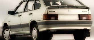
Operation, maintenance and repair manual for Daewoo Nexia
CONTENTS OF THE BOOK REPAIR, MAINTENANCE AND OPERATION MANUAL DAEWOO NEXIA petrol GENERAL INFORMATION 7 Overall dimensions of the DAEWO NEXYA vehicle 7 Technical characteristics of the vehicles 8 Vehicle markings 10 Safety precautions during vehicle maintenance and repair 11 Operating instructions for DAWOO NEKSIA 13 EQUIPMENT ENGINEERING AND CONTROLS 13 Keys to the vehicle 13 Doors 13 Central locking 14 Trunk lid 14 Fuel filler cap 14 Hood 14 Roof rack 15 Seats 15 Seat belts 15 Rear view mirrors 16 Power windows 16 Interior lighting 17 Trunk courtesy light 17 Sun visors 17 Glove box 17 Ashes prostrate 17 Cigarette lighter 18 Ignition switch (lock) 18 Gearbox lever 18 Parking brake DAEVOO NEXIA 19 Instrument cluster 20 Central lighting switch 21 Turn signal switch 21 Headlight switch 22 Windshield wiper switch 22 Wiper pause control 22 Windshield washer switch 22 Light direction control bunches headlights 22 Front fog lamp switch 22 Rear fog lamp switch 22 Rear window heating switch 23 Daewoo Nexia hazard warning light switch 23 Clock with digital display 23 Ventilation, heating and air conditioning system deflectors 23 Air temperature regulator 23 Fan operating mode switch 24 Air distribution regulator 24 Air recirculation mode switch 24 Air conditioning switch 24 Normal heating mode 24 Maximum heating mode 24 Deo Nexia window defroster 25 Normal cooling mode 25 Maximum cooling mode 25 Ventilation 25 Two-level ventilation mode 25 Audio system 25 Electrically driven antenna 27 MAINTENANCE Deo Nexia 28 Vehicle check before leaving 31 Checking the engine oil level 31 Changing the engine oil 31 Checking the gearbox oil level 32 Checking the coolant level 32 Replacing the coolant 33 Checking and replenishing the windshield washer fluid level 33 Checking the power steering fluid level 34 Checking the level and replacing brake fluid 34 Checking the fluid level in the hydraulic clutch reservoir 34 Replacing the air filter replacement element 34 Replacing the fuel filter 35 Checking the tension and replacing the air conditioning compressor drive belt 36 Checking the tension and replacing the generator and power steering pump drive belt 37 Replacing spark plugs 38 Adjusting the parking brake 39 Bleeding the brakes 39 Operating the battery 40 Wheels and tires 41 Replacing a wheel 41 Checking the condition of the front and rear brakes 42 Checking the timing belt 43 Replacing the windshield wiper blades 43 Maintenance schedule 43 CAR CARE 45 Washing the car 45 Protecting the paintwork 46 Window care 48 Wheel care 48 Engine care 48 Interior care 49 CAR REPAIR 50 ENGINE AND ITS SYSTEMS 50 A15MF engine 50 Replacing the timing belt 51 Replacing the valve lifter 54 Replacing the camshaft oil seal 55 Replacing the front knee oil seal chat shaft 56 Replacing the rear crankshaft oil seal 56 Removing the oil pressure sensor 56 Removing the oil pan 57 Removing the oil pump receiver (oil receiver) 57 Removing the left power unit support 58 Removing the right power unit support 58 Removing the rear power unit support 59 G15MF engine 60 Replacing the timing belt engine G15MF 61 Engine power supply system A15MF 62 Design description 62 Removing the engine air duct 63 Removing the air filter housing 63 Removing the throttle valve drive 64 Removing the throttle body 65 Checking and replacing the idle air control 66 Removing the electric fuel pump 67 Removing the fuel gauge sensor 68 Removing the fuel tank 68 Checking the pressure in the engine fuel system 69 Removing the pressure regulator 70 Removing the fuel rail and injectors, checking the injectors 70 Removing the recirculation valve 72 G15MF engine power supply system 73 Removing the throttle body on the G15MF engine 73 Removing the idle speed control on the G15MF engine 74 Removing the fuel rail and injectors on the G15MF engine 74 Removing the pressure regulator on the G15MF engine 75 Engine management system A15MF 76 Electronic control unit (ECU) 78 Control system fuses and relays 79 Control system sensors 80 Crankshaft position sensor 80 Coolant temperature sensor 81 Throttle position sensor 81 Absolute sensor pressure (vacuum) in the intake manifold 82 Intake air temperature sensor 83 Oxygen concentration sensor (.-probe) 84 CO potentiometer 84 Speed sensor 84 Ignition system 85 Ignition module 85 G15MF engine management system 86 Removing the coolant temperature sensor 87 Removing the position sensor throttle valve 87 Removing the intake air temperature sensor 87 Removing the cover, rotor and switch of the ignition distributor sensor 88 Removing and checking the ignition distributor sensor 89 Ignition coil 89 Checking and setting the initial ignition timing 90 Engine cooling system A15MF 91 Removing the coolant temperature indicator sensor fluid 91 Removing and checking the thermostat 92 Removing the expansion tank 92 Removing the radiator fan 93 Removing the radiator 94 Removing the coolant pump 95 G15MF engine cooling system 97 Removing the electric fan switch sensor 97 Removing the coolant temperature indicator sensor on the G15MF engine 97 Removing the thermostat on the G15MF engine 97 Exhaust gas system 98 Design description 98 Removing the exhaust pipe 99 Removing the compensating spacer (or catalytic converter) 99 Removing the additional muffler 99 Removing the main muffler 100 CLUTCH 101 Design description 101 Adjusting the clutch pedal travel 101 Bleeding the clutch hydraulic drive 101 Replacing the clutch housing and driven disc 101 Removing the clutch release drive mechanism 102 Removing the hydraulic clutch reservoir 103 Removing the master cylinder of the hydraulic clutch 104 Removing the working cylinder of the hydraulic clutch 105 Removing the hydraulic clutch hose 105 GEARBOX 106 Design description 106 Adjusting the gearbox control drive 106 Replacing the front wheel drive oil seal 107 Replacing the input shaft oil seal 107 Removing the speedometer drive 108 Removing the gearbox 108 FRONT WHEEL DRIVES 110 Design description 110 Removing the front wheel drives 110 Removing the outer joint 111 Removing the inner joint 112 FRONT SUSPENSION 113 Design description 113 Front wheel alignment angles 113 Removing the front suspension arm 114 Replacing the ball new support 115 Replacement silent block and front suspension arm cushion 115 Removing and disassembling the shock absorber strut 116 Removing the anti-roll bar 118 Replacing the front hub bearing 119 REAR SUSPENSION 121 Design description 121 Adjusting the rear wheel hub bearings 121 Removing the rear wheel hub bearings 121 Removing the rear wheel hub axle 122 Removal rear suspension shock absorber 123 Removing the rear suspension spring 124 Removing the rear suspension anti-roll bar 125 Removing the rear suspension beam 125 Replacing the silent block of the beam lever 126 STEERING 127 Adjusting the gap between the gear and rack 127 Removing the steering wheel 127 Removing and disassembling the steering column 128 Removing the end steering rod 129 Removing the steering mechanism 131 Replacing the steering gear cover 132 Bleeding the power steering hydraulic system 133 Removing the power steering reservoir 133 Removing the power steering pump 134 BRAKE SYSTEM 135 Design description 135 Bleeding air from the brake system 135 Replacing the front brake pads 135 Replacing the rear them brake Palds 136 Removing the parts of the front brake mechanism 137 Removing the main brake cylinder 138 Removing the vacuum brand amplifier 140 Removing the front brake hose 141 Removing the rear wheel cylinder 141 Removing the rear brake hose 142 Removing the parking brake system elements Removing the battery 146 Generator 147 Checking the generator 147 Removing and disassembling the generator 147 Starter 151 Removing the starter 152 Disassembling the starter 153 Headlights 155 Adjusting the headlights 155 Replacing lamps, removing the headlight 155 Electrical headlight adjuster 157 Removing the drive and adjuster for the electric headlight adjuster 157 Removing the turn signal, replacing the lamp 158 Removing the side turn signal and replacing the lamp 158 Removing the fog light, replacing the lamp and headlight trim 159 Replacing the lamps, removing the rear light 160 Replacing the lamp, removing the rear license plate light 161 Removing the additional brake signal (lamp), replacing the lamp 161 Removing the light switch reverse gear 163 Removing and disassembling the windshield wiper 163 Removing sound signals, adjusting the signal 166 Removing the interior lamp and replacing the lamp 167 Removing the steering column switches 167 Removing the windshield washer reservoir 168 Removing the instrument cluster, replacing lamps 169 Removing the cigarette lighter socket and replacing the cigarette lighter lamps and ashtrays 171 Replacing the backlight lamp of the heater control unit 172 Removing the front speakers of the sound reproduction system 172 Removing the rear speakers of the sound reproduction system 173 Removing the radio 173 Removing the antenna 173 BODY 175 Design description 175 Removing the radiator trim 175 Removing the hood lock and lock drive cable 176 Removal hood latch and safety hook 176 Removing the hood 177 Removing the outside rear view mirror 178 Removing the front wheel arch liner 178 Removing the engine compartment mudguard 179 Removing the front bumper 179 Removing the front fender 180 Removing the fuel tank flap cover 181 Removing the fuel tank flap lock 181 Removing the rear bumper 1 81 Removing the lock trunk lid 182 Removing the trunk lid 184 Removing the front door trim 185 Removing the front door interior handle 186 Removing the front door exterior handle 187 Removing the front door lock 188 Removing the front door lock drive 189 Removing the front door lock electric drive 189 Adjusting the door lock latch 190 Removing the front door glass 190 Removing the front door power window mechanism 190 Removing the rear door trim 191 Removing the rear door interior handle 192 Removing the rear door outer handle 192 Removing the rear door lock 193 Removing the rear door electric window lock 194 Removing the rear door power window mechanism 194 Removing the rear door windows 195 Removing the interior rear mirror view 196 Removing the sun visor 196 Removing the ceiling rail 197 Removing the front seat and slide 197 Removing the rear seat 199 Removing the instrument panel 199 HEATING, VENTILATION AND AIR CONDITIONING SYSTEM 204 Design description 204 Removing the electric heater fan 205 Removing the additional resistance of the fan motor 206 Removing the guide fan casing 206 Removal pneumatic chambers for the heating and ventilation control damper drives 207 Removing the outside air intake casing 208 Removing the heater radiator 208 Removing the electric fan of the condenser heat exchanger 210 Removing the condenser heat exchanger 211 Removing the air conditioning system receiver 212 Removing the evaporator heat exchanger 213 TROUBLE DIAGNOSIS 214 Engine and its systems 214 Clutch 229 Gearbox 231 Drives , chassis, steering, braking system 232 Body 240 Electrical equipment 242 APPLICATIONS 249 Tools used in vehicle maintenance and repair 249 Tightening torques for threaded connections 250 Recommended fuels, lubricants and operating fluids 252 Lamps used in the vehicle 253 Spark plugs 253 Electrical circuits ( electrical circuit diagrams) 254
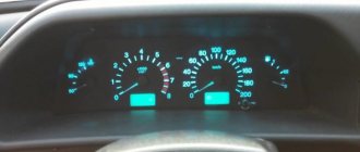
Dashboard lighting
Back to the Daewoo Nexia club I'm interested in whether anyone has changed their dashboard lighting. This refers to its color. Maybe this was discussed somewhere, but I couldn’t find it... I changed the topic before, but he left our ranks as a Daewoo driver =(((he just changed the standard ones to blue ones, but in general you need to completely disassemble them, buy Oracle or something like that, use it to glue those places where you need the right light and that’s it... Quote: [email protected] ! from March 25, 2009, 10:46:55 PM Quote: [email protected] ! from March 25, 2009, 10:46:55 pm Oracle - what is it? Is there some kind of film? How is the backlighting done there? Maybe you can also change the diodes to a different color, if they are there at all..? Oracle is a film... as soon as it gets warmer I’ll deal with all this nonsense... I want to make a different backlight for the stove too... I think it will be more difficult to get there... Quote: dreammas from March 25, 2009, 22:49:56
There are simple incandescent lamps with a light filter. I was also thinking about changing to LEDs... Replacing the lamps is not difficult, the lamps are baseless. And the panel can be easily removed, if anyone is interested, read the “Literature” topic, otherwise Loki tries to post it, but no one uses it, and everything is written there...
I saw a blue light at Tema’s, he just changed it, but clearly not a fountain, in bunches from where they stood from there in a bunch and the light... if you need to do it well, it’s better to surf the Internet and dig up information about parsing... gluing Oracle to places where should shine through and you need to find out how to illuminate the arrow, it will be absolutely gorgeous! Quote: Lion from March 25, 2009, 10:57:03 pm clear... I’ve been reading everything for a long time now (dashboard, heater controls, all the buttons, only the emergency lights were left red and two were inoperative video) changed to blue. If you have hands and they grow from the right place, then everything is done simply, although you will need to tinker a little with the buttons. As for the result, I like it. The dashboard and buttons are well illuminated, the stove is a little worse. If you want everything to be super, like an optitron, then there’s a guy in our city who does this. Tell me how you changed it =))) and about the guy, are you by any chance from IMHO tuning? Quote: russt from March 25, 2009, 23:09 :04how did you change it? did you change the filters? or did you install more diodes? I just changed the light bulbs in the dash to orange 5-watt ones (the original 3). It became much prettier.
initially: 1. illumination of the speedometer and tachometer: 4 light bulbs with green caps for 3 watts 2. illumination of the buttons, small bulbs for 1.2 watts with green caps what can be done: 1. in the buttons you can simply change the cap from green to the color you like, or paint the bulbs with tsaponlak . or plug in diodes.
2. stove control: either put the caps on. either glue it with oracal film.. or stick in diodes 3. speedometer: same with the stove, but don’t forget to set the bulbs to 5 watts and here’s what I got: speedometer: 5-watt bulbs painted with tsapon varnish buttons: changed the caps stove: pleka oracal photo below stove cool looks! So your pen doesn’t have a very bright light, how did you do it? I just drilled a hole and inserted an LED there, now it’s bright and tell me what the prices are for the Oracle film. To reduce the brightness of the LED, either you need to buy a weaker LED.. or more resistance. The oracle is usually a meter long... they cut off at least 10 cm... i.e. we get 100*10 cm, it used to cost 25 rubles for such a piece, but I also took some extra bright ones... now I don’t want to solder and disassemble something =((( I’ll seal them with something
What kind of oracal film is this? And where can I buy it? I really liked the stove lighting.
Quote: russt from March 27, 2009, 00:58:36 oracled this is a light-transmitting film. sold by advertisers.. the color range is very varied. Advertisers = advertising agencies? Is it self-adhesive or is it glued with some special glue? Quote: russt from March 31, 2009, 17:54:49 self-adhesive Quote: F1 from March 31, 2009, 14:32:07 can you tell me the address? Quote: F1 from March 26, 2009, 00 :37:06Tsapon varnish keeps the temperature in the buttons and the tidy properly? doesn't it spread? and also, do we have it in color? I just want to make the tidy exactly the same (orange) or mix it with dyes, what kind of thread will it be necessary? Quote: Griffith666 from March 11, 2010, 18:08:24 and you just take off the caps - you’ll get an orange flower. Anyone who can help make such a backlight would be grateful, otherwise I am not qualified in this field. Thanks in advance =) Quote: Smile132 from October 28, 2010, 20:00:55 fill out your profile, otherwise it’s not clear where you are from
Help me find the pinout of the instrument panel connectors on the GLE
According to the diagram, there is some kind of resistance there, but I don’t know what it is. And where this wire comes from is not indicated on the diagram. Unfortunately, I don’t remember from memory, but I wouldn’t be surprised if this contact is free. These connectors generally have a lot of free contacts. In principle, everything that is involved in Uzbek cars is listed.
The dashboard of a car is visual information about the most important parameters and characteristics, the state of the car’s systems and components. We offer a detailed description of the instrument panel sensors on the Daewoo Nexia, which will help the owner notice the malfunction in time and promptly fix it.
