Pinout of the ignition switch VAZ-2101 - VAZ-2107
The ignition switch on these cars is located to the left of the steering column. It is fixed directly to it using two fixing bolts. The entire mechanism of the device, except for the upper part in which the keyhole is located, is hidden by a plastic casing.
On the visible part of the ignition switch housing, special marks are applied in a certain order, allowing inexperienced drivers to navigate the lock activation mode when the key is in the hole:
- “” – a mark indicating that all systems, devices and instruments that can be turned on using the lock are turned off (this does not include the cigarette lighter, interior lighting, brake light, and in some cases the radio);
- “I” is a mark informing that the vehicle’s on-board network is powered from the battery. In this position, the key is fixed independently, and electricity is supplied to the ignition system, to the electric motors of the heater and windshield washer, instrumentation, headlights and light signaling;
- “II” – engine start mark. It indicates that voltage is applied to the starter. The key does not lock in this position. If you release it, it will return to the "I" position. This is done so as not to subject the starter to unnecessary loads;
- “III” – parking mark. If you remove the key from the ignition in this position, the steering column will be locked with a latch. It can only be unlocked by inserting the key back and turning it to position “0” or “I”.
The ignition switch has five contacts and, accordingly, five terminals, which are responsible for supplying voltage to the desired unit. All of them are numbered for convenience. Each pin corresponds to a wire of a certain color:
- “50” – output responsible for supplying current to the starter (red or purple wire);
- “15” – terminal through which voltage is supplied to the ignition system, to the electric motors of the heater, washer, and instrument panel (double blue wire with a black stripe);
- “30” and “30/1” – constant “plus” (pink and brown wires, respectively);
- “INT” – external lighting and light signaling (double black wire).
Pinout of the VAZ-2109 ignition switch with unloading relay:
- comes 12V in position I, II, III (parking)
- comes 12V in position I, II, III (parking)
- 12V comes to position III (parking)
- position I, 12V goes out after turning on the ignition (contact 15/2), disappears at start (II);
- position I, 12V goes to the starter (pin 50);
- position I, 12V goes out after turning on the ignition (pin 15), does not disappear when starting II;
- 12V comes from the battery (pin 30);
- 12V comes constantly.
Pinout of the new VAZ-2109 ignition switch:
- comes 12V constantly
- comes 12V constantly
- 12V comes after turning on the ignition (pin 15), does not disappear when starting II;
- 12V comes in after turning on the ignition (contact 15/2), disappears at start (II);
- position I, 12V goes to the starter (pin 50);
- 12V comes after turning on the ignition (pin 15), does not disappear when starting II;
- 12V comes from the battery (pin 30);
- 12V comes constantly.
Pinout of the ignition switch VAZ-2110:
- 12V comes for the sensor mic of the inserted key;
- the mass comes when the driver's door is open;
- 12V goes to the starter (pin 50);
- 12V goes out after turning on the ignition (pin 15);
- 12V goes out when the key is inserted to pin 5 of the BSK;
- comes 12V to illuminate the lock cylinder;
- 12V comes from the battery (pin 30);
- not used.
How to remove the lock
To do this you need to have:
- plus and slotted screwdrivers;
- awl.
If you don’t have a knitting needle, a long, thin nail with a cross-section of one and a half to two millimeters with a wide head, or a screwdriver used to unscrew small screws, will do. Also, before removing the lock, the negative terminal is removed from the battery. But this must be done extremely carefully, even despite the fact that a current of 12 volts is, in principle, not dangerous, but you can inadvertently cause a short circuit in the wire, which will most likely render the electrical equipment of the machine out of working order.
If everything is done correctly and you have all the necessary tools, you can proceed to the procedure:
- The key is inserted into the ignition switch and turned ninety degrees, namely to the zero position. This is necessary so that the clamp holding the steering shaft does not interfere with dismantling.
- Then the steering wheel cover is removed by unscrewing the five screws that hold all its parts in place.
- Then you need to carefully lift the top of the casing and pull it up. Then remove the upper and lower parts.
- Next, you need to unscrew the screws that connect the ignition switch. They are located below the switch and on both sides of it.
- Then the wires are disconnected from the mechanism.
- Now you need to insert a spoke into the hole on the bracket, which is located on the left of the mechanism, and forcefully press the latch into it.
- Once completed, the device is removed from the bracket using a slotted screwdriver.
Note: if you cannot remove the switch from the bracket, it means that the latch was not tightly clamped. Press it with the knitting needle, and then, without turning the key, move it slightly from side to side. In this way, you will press the latch all the way and pull out the key without any problems.
Lock malfunctions
A mechanical failure includes a problem with the secretion. Due to debris that gets inside the secretion and moisture, corrosion is formed, which prevents the movement of moving elements inside the secretion. As a result, the lock begins to jam when you turn the key, jams, or stops rotating altogether. This problem can be eliminated by pouring WD-40 or at least brake fluid inside.
An electrical fault is the burning of the nickels of the contact group. Because of this, there will be no or insufficient contact between the runner and the nickel. Electrical appliances on the car will not work, and there may be no power supply to the starter. If the burning was minor, then you can try to restore the functionality of the lock by cleaning the nickels with a diamond file, followed by wiping with alcohol or gasoline. But if the nickels are badly burnt, then you will need to either change the contact group or the lock assembly.
DETAILS: Replacing the front brake discs of a VAZ 2110
- Problem with the key. It turns slowly or doesn't turn at all. A temporary solution to the problem may be to use a penetrating lubricant, for example, VD-40. But do not forget that this is a temporary solution and you will need to replace the lock in the near future. If you do not pay attention to the jamming cylinder, then most often it ends in the key breaking;
- Problem with the operation of the instrument panel. When the key is turned to the second position, the indicator lamps do not light up. This malfunction can be solved by replacing the group of contacts;
- Starter problem. When turning the key to start the power unit, the starter does not operate. Usually this problem is related to the contact group. In order to accurately determine that a group of contacts has become unusable, you need to measure the voltage at contact 50 at the moment the key is turned.
How to check the contact ignition system
A technique for checking the ignition system can be useful when the engine stubbornly refuses to start. There may be many reasons for this, but you still need to start with the ignition.
Video tutorial on the VAZ ignition system: contact and non-contact
The ignition system is checked in the following sequence:
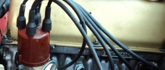
- checking the tightness of the high-voltage wires on the distributor cover, on the spark plug caps and the central wire on the ignition coil;
- the contact is checked on the wire from the coil to the distributor and on the wires going to the coil;
- after this, the presence of voltage on the coil is checked - with the ignition on, the voltage at terminal b+ of the coil is checked with a tester or using a probe;
- if everything is normal with the voltage, further along the circuit the presence of a spark is checked on the central wire of the distributor - it is removed from the central socket, the motor is cranked with the starter and a spark is caught between the wire contact and ground;
- The spark is checked on each of the high-voltage wires and on each of the spark plugs, simultaneously checking their condition.
The spark plugs must be of normal working color, free of deposits, soot and oil, and the gap between the electrodes must be 1 mm. If there is no spark at the outlet of the distributor, the cause may be a broken distributor cover, a microcrack in it, or a malfunction of the contact group, destruction of the slider. Every self-respecting owner of a six must have both a slider and a working cover in stock. This will save your nerves on a rainy November evening when the engine refuses to start. In principle, you can try to repair the slider by checking the resistance and condition of the contact, but no one did this even in the ancient Soviet times.
Special attention should be paid to the state of the contact group. The gap between the contacts must correspond to the factory rating - 0.36-0.4 mm. The contacts must be clean, without traces of sparking. If we have already reached the contacts, we can clean them with a zero file or polishing sandpaper. If everything sparks, rotates and shows signs of life, you can safely begin adjusting the ignition.
Correctly set ignition will reveal the full potential of the VAZ 2106 engine and will affect the stability of the engine at idle and in transient modes, as well as ensure optimal fuel consumption and normal dynamics. There is a class of drivers who can drive for years with a broken ignition and mumble about how Fiat engines “don’t work” or have high consumption. In most cases, the culprit for this is an incorrectly set contact ignition, since the public is accustomed to dealing with electronic or contactless ignition, where the adjustment procedure is carried out in one minute.
Just in case, let’s be clear and remember that the point of setting the ignition timing with your own hands is to ensure that the spark that jumps on the spark plug jumps before the piston reaches the top dead center of the compression stroke. Each engine has its own value, and for the VAZ 2106 it is 1 degree. 2101, for example, has 3 degrees. Advance is necessary so that the fuel burns completely in the chamber and does not interfere with the movement of the piston. The ignition timing is adjusted according to a specific algorithm.
There is nothing complicated about this, just follow the procedure and nominal angles and gaps:
- The spark plugs are unscrewed and the compression stroke is found in the 4th cylinder, since the adjustment is carried out specifically on the 4th cylinder. To do this, install a plug in place of the spark plug or cover the hole with a finger, crank the engine, and when the plug pops out, the compression stroke is found.
- Align the long mark on the front engine cover with the mark on the crankshaft pulley. The long mark shows the zero advance angle.
- In this case, the distributor slider must be strictly perpendicular to the cylinder head.
- The spark plug is connected to the wire of cylinder 4 and set to ground so that the presence of a spark is visible.
- Turn the crankshaft a quarter turn counterclockwise.
- Turn on the ignition and crank the crankshaft until a spark appears on the spark plug.
- Check the position of the crankshaft relative to the marks.
If necessary, adjust the advance angle by turning the distributor so that the spark jumps within the range between the long and middle marks.
After this, the ignition angle is checked while driving. With the heated six, they drive out onto a flat section of the road and accelerate to 40 km/h in fourth gear. At the same time, sharply press the accelerator pedal. With the ignition set correctly, the engine should detonate for a few seconds and then continue to accelerate. If the detonation does not stop, it means the ignition is too early; if the engine does not detonate at all, there is no characteristic knock of the piston pins, then the ignition is too late. Ignition adjustment can be carried out using a strobe light, but on the contact system you can use the method described above or, instead of a spark, rely on a test lamp connected to the contact gap on the ignition distributor.
- News
- Workshop
Ban on hand-held traffic police radars: in some regions it has been lifted
Let us recall that the ban on hand-held radars for recording traffic violations (models “Sokol-Visa”, “Berkut-Visa”, “Vizir”, “Vizir-2M”, “Binar”, etc.) appeared after a letter from the head of the Ministry of Internal Affairs Vladimir Kolokoltsev about the need fight against corruption in the ranks of traffic police officers. The ban came into force on July 10, 2020 in many regions of the country. However, in Tatarstan traffic police inspectors...
Demand for Maybachs has increased sharply in Russia
Sales of new luxury cars continue to grow in Russia. According to the results of a study conducted by the Autostat agency, at the end of seven months of 2020, the market for such cars amounted to 787 units, which is 22.6% more than in the same period last year (642 units). The leader of this market is the Mercedes-Maybach S-Class: this…
Video of the day: electric car reaches 100 km/h in 1.5 seconds
The electric car, called Grimsel, was able to accelerate from zero to 100 km/h in 1.513 seconds. The achievement was recorded on the runway of the air base in Dübendorf. The Grimsel car is an experimental car developed by students from ETH Zurich and the Lucerne University of Applied Sciences. The car was created to participate...
The regions of Russia with the oldest cars are named
At the same time, the youngest vehicle fleet is in the Republic of Tatarstan (average age is 9.3 years), and the oldest is in the Kamchatka Territory (20.9 years). The analytical agency Autostat provides such data in its study. As it turned out, besides Tatarstan, only in two Russian regions the average age of passenger cars is less than...
Fresh photos of the new Kia Rio and Hyundai Solaris have been published
As in previous times, in both cases we are talking about the Kia K2 and Hyundai Verna models, which are sold in China. However, these are the models that are taken as the basis for the Russian versions of the Kia Rio and Hyundai Solaris, so we can say with confidence that these are the changes that await us. As you can see from the picture...
Four homeless people and a priest drove on tractors from Poland to France
The travelers plan to drive their mini-tractors, whose speed does not exceed 15 km/h, all the way from the Polish city of Jaworzno to the Basilica of St. Therese in the French city of Lisieux, Reuters reports. According to the idea of the participants of the unusual run, the 1,700 km journey should become an allusion to the famous David Lynch film “The Straight Story”...
Mercedes will release a mini-Gelendevagen: new details
The new model, designed to become an alternative to the elegant Mercedes-Benz GLA, will receive a brutal appearance in the style of the Gelendevagen - Mercedes-Benz G-Class. The German publication Auto Bild managed to find out new details about this model. So, if you believe insider information, the Mercedes-Benz GLB will have an angular design. On the other hand, complete...
New Kia sedan will be called Stinger
Five years ago, at the Frankfurt Motor Show, Kia unveiled the Kia GT concept sedan. True, the Koreans themselves called it a four-door sports coupe and hinted that this car could become a more affordable alternative to the Mercedes-Benz CLS and Audi A7. And now, five years later, the Kia GT concept car has transformed into the Kia Stinger. Judging by the photo...
Moscow car sharing is at the center of a scandal
As one of the members of the Blue Buckets community, who used it, said, the company, in the event of an accident involving a rented car, requires users to compensate for the cost of repairs and additionally charges a fine. In addition, service cars are not insured under comprehensive insurance. In turn, representatives of Delimobil on the official Facebook page gave official...
In the Stavropol region, the use of hand-held radars was again allowed
The head of the State Traffic Safety Inspectorate for the Stavropol Territory, Alexey Safonov, spoke about this, RIA Novosti reports. The head of the local State Traffic Inspectorate said that during 1.5 hours of work, 30 speed limit violations were recorded. At the same time, those drivers are identified who exceed the permitted speed by 40 km/h and above. At the same time, Safonov proposed introducing criminal liability...
HOW to order a car from Germany, how to order a car from Germany.
How to order a car from Germany There are two options for purchasing a used German car. The first option involves an independent trip to Germany, selection, purchase and transfer. But this method is not suitable for everyone due to lack of experience, knowledge, time or desire. The solution is to order a car...
The most stolen car brands in St. Petersburg
Car theft is an age-old confrontation between car owners and thieves. However, as noted by law enforcement agencies, every year the demand for stolen cars changes noticeably. Just 20 years ago, the bulk of thefts were made from products of the domestic automobile industry, and in particular from VAZ. But…
23
While operating a VAZ 2106 car, the car owner may encounter difficulty starting the engine and interruptions in the operation of the power unit. The cause of such malfunctions is incorrectly set ignition timing, which requires timely adjustment. This kind of work is not particularly difficult, so even those car owners who have little idea about repairing their car can handle it. In this article we will tell you how to set the ignition on a VAZ 2106.
Lock selection
The structure of the ignition switch is the same on all classic VAZs. We recommend giving preference to the manufacturers DMZ, DAAZ, PROMS.
- The original number of the complete lock (with six contact pads) is 2101-03704000-11.
- The original number of the contact group (with six contact pads) is 2101-3704100.
It is worth noting that on cars produced before 1986, a seven-pin pad was installed. Locks with seven contact pads are often no longer available for sale. You can get out of this situation by connecting two wires and connecting them to terminal fifteen. In this case, the ignition switch will be operational.
Contact ignition VAZ 2106
In the photo - VAZ 2106, which is an exact copy of the Fiat 124
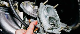
Different ignition systems were installed on the car at different times, but the Fiat contact design is considered a classic. Its design is incredibly simple - an ignition coil, a distributor, a bundle of high-voltage wires and the right spark plugs. This is all that is needed for the correct operation of the engine. On the first batches of sixes, until 1980, a P125-B distributor of the simplest design without vacuum adjustment of the ignition timing was installed. After installing the standard Ozone carburetor, it became possible to equip the distributor with a vacuum advance angle adjustment system.
Structurally, distributors differ only in the presence of a vacuum membrane chamber, which is connected to the primary chamber of the carburetor. At a certain period, a distributor was installed without a vacuum chamber and it was structurally similar to the old one. Reel B117-a, sealed, filled with oil, with open magnetic conductors. In short, there is practically nothing to break. All that remains is to check the condition of the system elements and you can begin adjusting.
Scheme and principle of operation of BSZ
All elements of the system are connected to each other and to the engine as follows:
- The distributor shaft rotates from the motor drive gear;
- The Hall sensor installed inside the distributor is connected to the switch;
- the coil is connected by a low voltage line to the controller, a high voltage line to the central electrode of the distributor cover;
- high-voltage wires from the spark plugs are connected to the side contacts of the main distributor cap.
The threaded clamp “K” on the coil is connected to the positive contact of the ignition switch relay and terminal “4” of the switch. The second clamp marked “K” is connected to contact “1” of the controller, and the tachometer wire also comes here. Terminals “3”, “5” and “6” of the switch are used to connect a Hall sensor.
The main role in the BSZ “six” is played by the switch, which processes the Hall sensor signals and controls the operation of the coil
The algorithm looks like this:
- After turning the key in the lock, voltage is supplied to the electromagnetic sensors of the first winding of the transformer. A magnetic field arises around the steel core.
- The starter rotates the engine crankshaft and distributor drive. When a screen slot passes between the sensor elements, a pulse is generated and sent to the switch. At this moment, one of the pistons is close to the top point.
- The controller, through a transistor, opens the circuit of the primary winding of the coil. Then a short-term pulse of up to 24 thousand volts is formed in the secondary, traveling along the cable to the central electrode of the distributor cover.
- Having passed through a moving contact - a slider directed towards the desired terminal, the current flows to the side electrode, and from there through the cable to the spark plug. A flash forms in the combustion chamber, the fuel mixture ignites and pushes the piston down. The engine starts.
- When the next piston reaches TDC, the cycle repeats, only the spark is transferred to the other spark plug.
Compared to the old contact system, BSZ produces a more powerful spark discharge
For optimal combustion of fuel during engine operation, a flash in the cylinder should occur a fraction of a second earlier than the piston is in the maximum upper position. For this purpose, the BSZ provides for advance of spark formation by a certain angle. Its value depends on the crankshaft speed and the load on the power unit.
The advance angle is adjusted by the switch and the vacuum unit of the distributor. The first reads the number of pulses from the sensor, the second operates mechanically from the vacuum supplied from the carburetor.
- Open-end wrench for ten;
- Crosshead screwdriver;
- Small slotted screwdriver.
What is contactless ignition and its advantages
Another interesting option for tuning classic models is installing a contactless ignition type. Definitely, the car only benefits from such an innovation - the engine runs smoother, dips disappear when accelerating the car , and it is much easier to start the engine in cold weather. In addition, there are savings associated with fuel consumption.
The wiring diagram on the VAZ 2106 in this case is almost identical: the main differences are the presence of a pulse sensor and the absence of a distributor. While the engine is running, the sensor creates pulses that enter the transistor switch.
Already with its help, other impulses are generated, characteristic of the primary winding on the coil. With interruption, the secondary winding produces high voltage current. From the distributor contact, current is supplied to the spark plugs in the required sequence.
So, you purchase a non-contact ignition package for a VAZ “classic”, which must match the characteristics of the car’s engine. Next, we will need a wiring diagram for the VAZ 2106.
The following spare parts should be included in the configuration of such an ignition:
- switching unit;
- coil;
- high voltage wiring kit;
- spark plugs - DVRM;
- connecting wires.
Stages of work
To successfully replace the ignition with a contactless one, it is important to adhere to the principles of following the correct work technology. Remove the negative terminal from your battery. Any type of electrical repair should always begin with this action.
This is where the wiring for the VAZ 2106 will come to the rescue:
- We disconnect the wires and the main high-voltage wire from the ignition coil.
- Remove the distributor cover.
- The slider should be placed so as not to disturb its necessary settings.
- The mark on the block is placed where there are slots at the bottom of the distributor body.
- Unscrew the nut and take out the old distributor of the previous contact ignition system.
- Before installing the new system, open the cover of the updated distributor and place the slider in the same position as on the old distributor. You can put it in the hole in the block head.
- Move the mark to the required level and tighten the nuts.
Now you can assemble, as the VAZ 21063 wiring diagram suggests - put on the cover, connect the high-voltage wires. You can begin to dismantle the old ignition coil (this was discussed above).
- We install a new coil and connect another outlet of the high-voltage wire to it.
- Now we put all the high-voltage wires in their places. We will need pin “K” for the brown wires of the new coil, while the blue wires will go to pin “B”.
- You need to choose a place to place the switch, most often this is done in the area of the washer reservoir. It is secured with self-tapping screws.
The VAZ 2106 wiring has been replaced, you can tighten the wires with electrical tape. All that remains is to start the engine and adjust the operation of the ignition system.
Note! If the engine of your “six” begins to work intermittently and intermittently, and this is also accompanied by a loss of power, then the cause could easily be misfires.
The first thing you should pay attention to in this case is the integrity of the wiring, including high-voltage, as well as the serviceability of other elements of the ignition system. Spark plugs are checked on a separate stand. In some cases, the cause may be a faulty VAZ 2106 generator and the wiring to it.
Scheme and principle of operation of BSZ
After removing the decorative casing, unscrew the two screws securing the ignition switch to the body, then insert the key into the lock and turn on the “0” position, which turns off the anti-theft device. Through the hole in the bracket, press the lock lock with a thin awl and remove the ignition switch from the mounting socket. This completes the repair work to remove the ignition switch.
To replace the contact group of the ignition switch, you need to use a thin screwdriver or an awl to pry the retaining ring from the edge and remove the contact part. When installing a new contact part, orient it so that terminals “15” and “30” are on the side of the locking rod.
At this point, the repair work is completed, install the new ignition switch in the reverse order of removal, connect the wires, transferring the markings from the old switch to the new one. The pinout or connection diagram of the VAZ ignition switch wires is quite simple and understandable, so every car enthusiast can carry out repairs or replace a spare part without the help of car service employees.
Mechanical part
Voltage is supplied to a given circuit at a certain key position. The color depends on the year of manufacture of the car. As a rule, such a problem leads to a broken ignition key, which, in turn, requires additional expenses for purchasing a new part.
Unlocking Take an awl and insert it into the hole, pressing the latch with it. If there is no diagram or it is lost, then read on. At the same time, they forget that electricity can affect not only the hand, but also car parts. Read it in 6 minutes. Often such a malfunction ends with the ignition key breaking and, as a rule, replacing the VAZ ignition switch. Mechanical part. Often, failure of the ignition switch in the mechanical part is provoked by: tight turning of the ignition key; jamming in one of the positions.
The mechanical part is installed directly in the ignition switch itself.
Therefore, the key closes the contacts of the ignition circuit, thereby starting the car engine. After removing the lock, pull off the retaining ring from its reverse side and install a new contact group as in the photo. To replace it you must: Disconnect the battery Remove the plastic casing, having first unscrewed the screws that secure it. This will help them connect the part without much hassle. VEHICLE ELECTRICAL EQUIPMENT.
Replacing the contact group and installing the ignition switch
Some VAZ 2106 owners install a button for ease of starting the engine. It is connected via the starter power circuit to the break in the red wire, which goes to terminal 50 of the ignition switch. In this case, the engine starts as follows:
- The key is inserted into the lock.
- Turn it to position I.
- The starter is started by pressing the button.
- When the engine starts, the button is released.
To stop the power unit, you must turn the key counterclockwise. A slightly different option for connecting the button is also possible, so that with its help you can not only start the engine, but also turn it off. For these purposes you will need the following parts:
- headlight relay RS 711;
- starter relay 113.3747–10 or 90.3747–10.
In order to turn off the engine, the button must be connected in a slightly different way.
According to the diagram, when the button is pressed, power is supplied to the headlight relay, and after the contacts are closed, to the starter. When starting the power unit, the button is released, thereby opening the contacts of the starter relay and breaking its power circuit. If you press the button again, the contacts of the switching device open, the ignition circuit is broken and engine operation stops. The second option for using the button is called “Start-Stop”.
Even a car owner who is encountering such a problem for the first time can replace or repair the ignition switch on a VAZ 2106. To carry out the work you will need a minimum of tools and following step-by-step instructions. The main thing is to connect the wiring to the lock in accordance with the diagram.
Many owners of “classics” install a button to make starting the engine more convenient. The button is connected to the starter power circuit, into the gap in the red wire which is connected to pin 50 on the lock. The engine is started according to the following algorithm:
- The key in the lock is set to position one.
- Turn on the starter by pressing the button.
- As soon as the engine starts, the button is released and movement begins.
- In order to stop the engine, you need to turn the key to position zero.
How can you remove the ignition switch on a VAZ-2016 yourself?
Before you begin any troubleshooting work on your car, you should prepare a certain set of tools. In the case of removing the ignition switch on the “six” we will need:
- screwdrivers - flat and Phillips;
- awl.
However, you can do without the latter. An awl can be perfectly replaced by, for example, a miniature screwdriver, or a thin long nail with a cross-section of no more than 2 millimeters. One point should also be noted. Before disassembling the ignition switch, it is recommended to disconnect the negative terminal from the battery. Many may argue that a voltage of 12 volts is practically safe for humans.
However, do not forget that in the process of work you may well short-circuit the wires and damage any electrical equipment.
Accordingly, additional, completely unnecessary problems will appear.
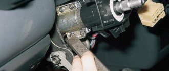
It's time to start disassembling directly. To do this, first of all, insert the key into the lock and turn it so that it is in position “0”. This is a very important point. This must be done so that the pin, with which the steering shaft is kept from turning, disappears a little in the “secret” part of the lock, and does not create interference during disassembly. After this, you should open the 5 screws holding the upper and lower parts of the steering column housing and remove them. A certain amount of care is required here so as not to break anything. The upper part of the casing should be pulled up, first lifting it, and then removed, along with the lower one.
Now we need to find 2 screws that secure the ignition switch itself. You will immediately notice them - at the bottom of the switch, on the left and on the right. There is very little left. In particular, you should disconnect the wires from the ignition switch contacts. Now we find a flat slot on the right, stick an awl into it, and then press on the latch, applying a certain force. Next, pry up the lock with a flat-head screwdriver and remove it from the bracket.
Pay attention to one thing. The lock should be removed without any problems. If, despite the efforts made, it stubbornly does not want to come out of the bracket, it means that you did not press the latch all the way. In this case, you should follow one simple procedure. Press the awl onto the latch, and at the same time move the key slightly from side to side, just do not turn it.
Conclusion
When replacing this element, you should be very careful, since if it is connected incorrectly, the entire ignition circuit will stop working and you will not be able to start the engine. Also, if the contacts are mixed up, you can provoke increased voltage on one of their nodes, which will certainly lead to its instant failure.
It is worth noting that this ignition switch connection diagram is suitable not only for the “six”, but also for the rest of the VAZ “Classic” model range. This is quite convenient, since when choosing a new part, you will not have any special problems.
Electrical part
Even if the mechanical part of the ignition switch is fully operational, the terminal block still often fails. You can always replace it, since such a spare part is sold in any car store.
The terminal part often burns out itself or its contacts, which connect certain power supply circuits, burn out. It also happens that the central plastic insert melts, which opens and closes some contacts at different positions of the ignition key. This overheating is provoked by holding the key in the “starter” position for a long time, when the driver cannot start the engine of his vehicle for a long time.
In such cases, it is necessary to purchase a new terminal block, not an ignition switch.
It is very important that the connection remains unchanged. If you are replacing for the first time, you need to look at the bottom of the ignition switch and there draw the colors of the wire and the terminals to which they are connected. Each of them on the block has its own number, so it is very convenient to write down the wire color and terminal number so as not to confuse anything.
Wiring sequence
If you are lucky and have a special chip for connecting the lock, everything is simple. But if such an element is missing, then the wiring will have to be connected one by one. To do this, you need to take the terminal block of the inserted lock so that one double-type terminal is located on the right and stands vertically. The top of this terminal should have black wire attached to it.
Remember that the bottom area of the double view terminal must be left empty. So, the contacts are connected.
To connect to wires, the terminal block has the following pins:
- «15»;
- «30»;
- «30/1»;
- «50»;
- "INT".
First of all, you need to deal with the wiring. In principle, there is nothing particularly complicated here. When the key is in position one, a contact called 30-INT is turned on. He is responsible for lighting, windshield wipers, and washers. Also in this position, contact 30/1-15 is activated. The circuits turn on the heater, heated rear window, turns, the generator winding is excited, etc. The carburetor valve and ignition system are also ready to start working.
Installing a new lock
The ignition switch is disconnected. Now we can start connecting the new one.
We connect the contact group of wires
If you are lucky enough to become the owner of a chip that closes the wires, then simply connect it to the new lock.
If there is no chip, then we connect each wire separately. We take the terminal block of the new ignition switch in our hands so that the only double terminal located on it is on the right and in a vertical position. The top compartment of the double terminal corresponds to the double black wire.
Next we move counterclockwise. The next one to connect is the pink wire, followed by the double blue, then the brown, and the last one is red. In addition, you can figure out the location of the wires on the terminal block using the digital marks that mark the block itself. There is a designation near each terminal; let’s look at how the terminals correspond to the colors of the wires:
- 1NT – black double wire
- 30 – pink wire
- 15 – double blue wire
- 30/1 – brown wire
- 50 – red wire.
Removing a faulty device
To remove the ignition switch of a VAZ 2106, the following tools are required:
- positive screwdriver;
- slotted screwdriver;
- awl.
Replacing the ignition unit
If you do not have an awl, to dismantle the device, you can use a long thin nail with a cross section of 1.5-2 mm with a wide head or a screwdriver to unscrew small screws from the body of mobile phones.
Before carrying out the main procedure, it is necessary to remove the negative terminal from the battery. Despite the fact that a 12-volt current is practically harmless to the health of an adult, when removing the device, you can accidentally short-circuit the wires, which, in turn, can lead to the failure of important electrical equipment of the car.
Step-by-step instruction:
- To begin, insert the key into the ignition switch and turn it 90 degrees to the “0” position. This is necessary so that the pin holding the steering shaft from turning fits slightly into the secret part and does not interfere with dismantling.
- Next, you need to remove the plastic steering column cover. To do this, sequentially unscrew the 5 screws connecting the lower and upper parts of the casing.
- Then carefully lift the upper part of the steering column housing and pull it up. After this, remove both parts of the casing to the side.
- Next, find and unscrew the screws securing the device itself. There are two of them, they are located at the bottom of the switch, on the right and left.
- Then disconnect the wires from the ignition switch contacts.
- Next, find a flat slot on the bracket to the left of the device, insert an awl there and forcefully press the latch with it.
- After this, you can remove the device from the bracket by prying it with a slotted screwdriver.
Ignition includes:
- locking rod;
- body part;
- roller with contact disk;
- sleeve;
- protrusion on contacts;
- block;
- wide protrusion of the contact part.
Has the contact group burnt out, after which you have difficulty starting the starter? Change the ignition switch.
Before changing the device, prepare an awl and two screwdrivers - with a Phillips and a flat tip. If you don’t have an awl, you can use a nail; its width should be 2 mm and its length should be as long as possible. You also need to make sure that there is no voltage in the on-board network.
DETAILS: Electrical diagram of the VAZ 2106 with a description of the electrical equipment of the car, replacement and wiring diagram
So, how to properly replace the mechanism - detailed instructions with photos are presented below:
- Install the key in the 3Z and turn it 90 degrees so that it is set to position 0. This must be done, since in this case the pin with which the steering pulley is secured against rotation will go into the lock. In other words, this will prevent the pin from interfering with your further actions.
- Next, it will be necessary to dismantle the plastic protective cover of the steering wheel, since it is behind it that the device itself and all the connectors are hidden. To complete this task, you will need to unscrew five screws - with their help, the lower part of the cover is attached to the upper one.
- Once the bolts are unscrewed and removed, it will be necessary to lift the top of the trim and remove it. After this, both components of the protection are removed to the side.
- After completing these steps, you will need to unscrew the screws that secure the ignition switch. There are two bolts themselves, they are located to the left and right of the device. When the bolts are unscrewed, you will need to disconnect the wires connected to the contact group.
- In the next step, you will need to look at the left side of the device - here you will be able to see a small gap. You will need to insert an awl or nail into this gap, and then press the fastener itself.
- Having done this, you need to remove the device from the seat, and you will need to pry it off with a screwdriver. Once you have the ignition switch in your hands, you can either replace the device or repair it, depending on the need. If you don’t know how to put the lock back, then there is nothing difficult about it - the procedure is performed in the same way as removing it, only in the reverse order. To install, you need to insert the key into the new ZZ, and then set it to position 0. After this, the lower clamp is clamped, this will allow you to install the device in the seat. All necessary wires are connected in accordance with the pinout diagram, and the functionality of the installed unit is checked.
Each of the above elements has a separate design. If we look at the ignition switch in more detail, we can note such details as: locking console, housing, shaft, disk with contacts, bushing, block, and cutout of a group of contacts.
The locking console is responsible for locking the steering wheel in the absence of the ignition key in the lock. The case is a protective element and covers the entire structure of the lock. The shaft is responsible for the rotation of the disk with contacts in relation to the sleeve, and forms contact between them. The block and group of contacts, in turn, are connected to the general ignition system of the car, and transmit the resulting contact to the distributor, through the ignition coil.
Before starting work, be sure to prepare a bench tool, a file with a fine tip, and a multimeter. First of all, you need to remove the protective housing from the lock. Next, to remove the ignition switch, unscrew its fastenings and set the key to position “0” to disable the lock.
When connecting a new device, a special diagram must be followed, therefore, the contacts should be marked with a marker before disconnecting them from the part. Connecting a new lock is carried out strictly according to the pinout marked on its rim.
The VAZ 2106 ignition pinout is deciphered as follows:
- Value “0” - contacts 30 and 30/1, turn off the power system, transferring it to emergency operation.
- Value “I” - contacts 30/1-15 and 30-INT, include lighting systems (front and interior), windshield wiper, washer motor, heater and air conditioning fan, generator unit, instrument panel sensors, turn signals and sound signals, and also, the ignition system itself.
- Value “II” - contacts 30/1-15, 30-INT and 30-50, leave the previous elements turned on, with the exception of the ignition system, generator unit and panel instruments. Also, the starter circuit turns on and the engine starts running.
- Value “III” - contacts 30-INT and 30/1, considered the parking position, stops the starter circuit, leaving the lighting system, wipers, washer motor and cooling system working.
Lock pinout
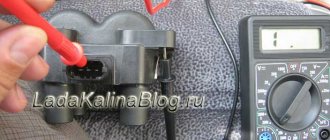
After the lock circuit is connected, test its performance in all modes using a multimeter. To do this, disconnect the battery terminal and install a multimeter between the contact and the battery positive. Turn the ignition key so that it activates the contact being tested.
The part of the lock hidden under the lining has the shape of a cylinder with a protrusion on the side, which is a lock for the anti-theft system.
At the end of this housing there are terminals to which the wires are connected. There are six of these pins in total, and each of them provides power to certain devices.
The contact group of the ignition switch 2101 is a special washer with leads for connecting wires. On the inside of it there are nickels of these conclusions, as well as a slider that moves due to the influence of the secretion on it. When moved to certain positions, this slider closes certain nickels with each other, providing electricity to the terminals that are connected to the closed nickels.
We take out the lock and disconnect the wires from the terminals.
It is very important that the connection remains unchanged. Press the latch and install the lock.
Using a screwdriver, unscrew the 5 screws of the steering column switch housing.
The mechanical part is installed directly in the ignition switch itself. Alternately move the wires from the previous part, choosing the correct contacts. The design of the electronic ignition on a VAZ consists of two elements: The electrical part is a wire terminal fixed at the bottom of the lock with a locking clip. In this case, it is important to remember that the connection diagram plays a huge role, and you should not mix up the wires.
Therefore, the key closes the contacts of the ignition circuit, thereby starting the car engine. Place the steering column cover in place and secure the two parts together.
Lock connection diagram
To understand the principles of operation of the ignition switch, you need to carefully study its connection diagram. It shows which nodes this part interacts with in the electrical circuit. The following work in the same circuit with the lock:
- starter;
- battery;
- generator;
- relay located in the mounting block;
- start relay.
The operation of the electrical wiring in interaction with the lock depends on the position of its cylinder. Each turn of the key changes the number of switched on electrical networks:
- At the zero position, only two terminals work, the rest of the electrical networks are turned off. These two terminals can lead to the anti-theft system so that it functions continuously.
- In the first case, power is supplied to the heater fan, side lights and windshield wipers. This position is called pre-start. It was invented so that the car enthusiast could prepare the car for use without loading the battery.
- In the second position, power is supplied to the ignition system, instrument panel display and switches, starter and turn signals. The car is in working order.
- In the third position, only the horn, side lights and windshield wipers are supplied with power. It is used to tow a car.
The ignition switch is a key element of the electrical circuit, which adapts it to the needs of the driver. When you turn the key, voltage is transferred from the negative terminal of the battery to the coil.
This unit is often used, so it often fails. You can restore it for a while using WD-40 spray, but you shouldn’t expect a long-term effect. The castle consists of several parts:
- locking rod;
- frame;
- roller with contact disk;
- sleeve;
- protrusion of the contact part, small and wide;
- block.
In most cases, if the lock does not work correctly, it is worth replacing it with a new one, but some car enthusiasts prefer to restore the part.
Ignition switch problems
Problems are possible with both the mechanical and electrical parts of the device.
One of the lock malfunctions is a problem with the key, when it turns tightly or does not turn at all. Quite often the situation ends with the key breaking, as a result of which part of it remains inside the mechanism. A solution to the problem of a jamming lock can be the use of a penetrating lubricant, for example, WD-40. But do not forget that this is just a temporary solution and the switch will still have to be replaced in the near future.