The ignition switch VAZ 2108 2109 21099 comes in old and new models: -The old one has four positions, a relay and a long key, -The new one has no relay and has a short key with three positions. The ignition switch has two functions: -Electric: closing contacts depending on the position of the key. -Mechanical: steering wheel lock without key. That is, without a key you will not be able to turn the steering wheel, even if you bypass the electrical part of the lock and start the car. To rotate the steering wheel, you will need to disassemble the lock and remove the mechanical lock. Malfunctions
In terms of the electrical part, the ignition switch of the VAZ 2108 2109 21099 has only two (as with all electrics): 1) Lack of contact in a certain position of the key.
In this case, the machine may or may not work for individual consumers. 2) The presence of contact where it is not needed. In this case, the lock begins to melt, smoke and emit a characteristic odor. Replacement
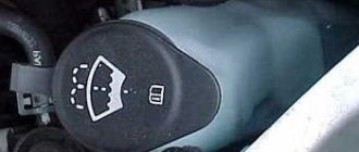
1) Remove the steering wheel cover. To do this, unscrew the screws securing the upper and lower parts to each other. Having removed the protection, we immediately gain access to the ignition switch and steering column switches.
2) Unscrew the plastic trim of the ignition switch with a screwdriver. Let's take it off.
3) Remove the contact group of the ignition switch.
It is connected to the rest of the wiring using a plug. If the replacement is made with a new type of ignition switch, then it will be necessary to slightly alter the wiring.
You can’t just connect it like that, since their wiring diagrams are different. 4) Then unscrew the mechanical part of the lock attached to the steering wheel.
We install the new lock in the reverse order. The ignition switch contact group is sold separately, which can be replaced without touching the entire lock. Checking for correct operation
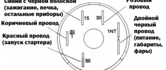
ignition switch VAZ 2108 2109 21099: To check whether the lock is working in case of suspicion, you need a diagram indicating which contacts are closed with each other at different positions of the key in the ignition switch.
The diagram is given below: Explanations for the diagram (according to the colors of the wires of the contact group): Red - to the starter, Pink - +12V, Brown - +12V to turn on the ignition relay, White - turn on the ignition relay, Black, blue - other consumers. Key position “0”: Not a single wire in the contact group should ring with others. All wires are open from each other. Key position “1”: In this position, the ignition relay is turned on and the ignition system of the VAZ 2108 2109 21099 is powered through the blue and black wires. White is connected to brown, pink to blue and black. Key position “2”: In this position, again, the ignition relay remains switched on, +12V is supplied to the starter switch relay. White is closed with brown, pink with red and black. Key position “3”: In this position, the circuits that provide illumination of the car, dimensions, and high beam headlight signaling are closed. Brown is closed with black, pink with black. A typical example of a contact group malfunction: the car does not start. You turn the starter... You start to blame the switch, Hall sensor, . But then it turns out that everything is fine, the ignition system is just not powered. That is, the ignition switch of the VAZ 2108 2109 21099 does not supply power to the ignition system.
On the VAZ 2109, electrical problems arise over time. An experienced motorist should be able to cope with these problems. It is advisable that he independently eliminate faults on the VAZ 21093i, check the electrical equipment and draw the appropriate conclusions. In this article we will try to help the novice driver and familiarize him with all the basic electrical elements and their malfunctions.
What is
First, let's look at the structure of the castle. Let's find out what it looks like, what it consists of, what its operating principle is, and so on:
- As was said, this is a very important element of the VAZ 2109 car, because almost all the available equipment is connected to it.
Note. Although there are components that do not depend on the lock in any way. Here they are: license plate lights, brake lights, parking lights, hazard lights, interior lights and lights on the dashboard.
- There are different types of ignition switches: new or old type. The first version without a relay has three positions and a short key, the second with a relay has four positions and a long key.
Scheme
Below is a typical diagram of the ignition switch on the “nine”.
Operating principle of the ignition switch
The lock's operating system is quite simple, so now let's look at the main tasks it can handle:
- The ability to connect and disconnect the vehicle’s electrical power system to the battery, in turn, after starting the engine, connect to the generator.
- Ability to connect and disconnect the engine ignition system to the power source.
- When the engine is started, the ignition switch may turn on the starter for a short period of time.
- Ensures the operation of such devices when the engine is off , such as: radio and alarm.
- Some ignition switch features can be used as an anti-theft feature , such as the ability to lock the steering wheel when the engine is at rest.
Ignition switches can have from two to four switch positions. Depending on the position of the ignition key in the car, you can determine which power systems are working at one time or another. The key in the car can only be pulled out in one position, when all power consumers are turned off. To have a more detailed understanding of the operation of the ignition switch, you need to familiarize yourself with its diagram:
Ignition switch operation diagram
In what positions can the ignition switch operate?
- "Turned off" . In cars of domestic manufacturers, this position is displayed as “0”, but on some older models the position had the value “I”. Today, in improved cars, this mark is not displayed on the lock at all.
- “On” or “Ignition” - on domestic cars the following designations are found: “I” and “II”, in newer versions it is “ON” or “3”.
- “Starter” - domestic cars “II” or “III”, in new cars – “START” or “4”.
- “Lock” or “Parking” - old cars are designated “III” or “IV”, foreign cars are marked “LOCK” or “0”.
- “Additional equipment” - domestic locks do not have this provision, foreign versions of the car are designated: “Ac” or “2”.
Ignition switch position diagram
When the key is inserted into the lock and turned clockwise, that is, it moves from the “Lock” to the “ON” position, then all the main electrical circuits of the car are turned on, such as: lighting, windshield wiper, heater and others. Foreign cars are designed a little differently; they have “Ass” immediately before the “ON” position, thus additionally starting the radio, cigarette lighter and interior lights. If you turn the key further clockwise, the lock will move to the “Starter” position, at this moment the relay should connect and the engine will start. This position cannot be locked because the key itself is held by the driver. After successfully starting the engine, the key returns to the initial position “Ignition” - “ON” and already in this state the key is fixed in one position until the engine stops completely. If it is necessary to turn off the engine, then in this case the key is simply turned to the “Off” position, then all power circuits are turned off and the engine stops.
Diagram of the key operation in the ignition switch
In cars with diesel engines, a valve is turned on to shut off the fuel supply and a flap that closes the air supply; as a result of all these actions, the electronic unit that controls the engine stops its operation. When the engine is completely stopped, the key can be switched to the “LOCK” position, after which the steering wheel becomes motionless. In foreign cars, in the “LOCK” position, all electrical circuits are turned off and the steering wheel is locked; cars with an automatic transmission additionally block the selector, which is in the “P” position.
VAZ 2101 ignition switch wiring diagram
Typical faults
The lock belongs to the car's ignition system. Let us note right away that if problems are observed, you can fix them yourself, because, as a rule, the “nine” is equipped with an outdated ignition system that does not require diagnostics and repair at a service station.
How to make sure there is a problem
Below is a tip on how to make sure that the ignition switch is really not working:
- We insert the ignition key and turn it to a certain position. A short circuit in the circuit must necessarily occur. We look at the diagram: if the key is in position “1”, is the external lighting or control devices working;
- It is recommended to check at all positions of the lock. If deviations from the norm are observed, there is a problem with the lock;
- You can also check the functionality of the ignition switch in the following way: turn the steering wheel, which should not be blocked. The lock on a working steering wheel should only work when the key is turned a second time from position “1” to position “2”;
- You can reliably check whether the lock works like this: take an ordinary portable lamp and connect one end to ground, the other to the lock. We turn on the ignition - if the light is on normally, then the lock is in order. If the light glows dimly or does not light at all, the lock is faulty.
Common faults
Among them, the following are in first place:
- The lock is jammed. This is even observed in the “nines” when a new lock is installed. The reason is a manufacturing defect or what is given below.
Note. The lock may also jam due to problems interacting with the starter. In this case, you need to inject a little silicone grease inside the lock and do this every time the lock jams.
- The lock may wear out over time and this will cause it to perform poorly;
- The ignition switch easily becomes unusable in the event of an unsuccessful attempt to steal a car, as well as any careless handling.
Let's sum it up
As you can see, ignition switches may differ from each other in connection type, functionality, purpose and other parameters. At the same time, all of them are structurally quite simple, which makes it possible for any car owner to correctly troubleshoot problems when identifying a malfunction.
As a summary, we note that the presence of a chip simplifies the connection, but this solution is often missing on older models. To avoid mistakes, without enough experience in this case, it is better to contact an experienced auto electrician who will quickly fix any problems with the ignition switch.
How does the engine start button work? Available options and solutions for installing the starter button yourself. How to install the engine start button yourself.
How to remove the engine start lock. Checking for random activation of the immobilizer and how to disable it. Diagnosis of possible alarm malfunctions.
Why the starter may not work after turning the key in the ignition. The main causes of starter malfunctions: bendix, traction relay, brushes, winding.
The alarm in the car does not work: there is no connection with the key fob or the main module is faulty, how to determine. Methods for emergency shutdown of alarms, tips.
The car alarm does not work: the main reasons for car alarm failures. How to accurately determine the reason: the key fob or control unit does not work.
Starline alarm with auto start: how to set up Starline auto start. Enabling Starline autorun remotely or automatically.
Repair and replacement
Typically, the lock can be repaired. If this fails, you will have to completely replace it (see). Repairing a lock in most cases comes down to replacing the cylinder or contact group. If after this the problem has not been resolved or it is possible to change the entire lock, then it is better to do the latter.
Larva and its replacement
So, we do the following:
- We remove the casing and unscrew the fastening bolts that tighten the ignition switch clamp.
Note. The bolts have sheared heads and then you will have to use a hammer and chisel. The bolts are first loosened by blows with a chisel, and then unscrewed with pliers.
- We separate the two parts of the clamp so that they disengage;
- The larva can be changed already at this stage of the operation;
- We take out the side pin that holds the cylinder in the lock.
Advice. The cylinder can be easily removed with a thin screwdriver, for example, from a watch. At the same time, you need to tap the lock with a hammer.
- If you cannot pull out the cylinder after the side pin has been removed, you can try to drill out the cylinder using a thin drill;
- If again it was not possible to remove the cylinder, then it is recommended to finally remove the lock;
- Remove the wire plugs.
Note. One of the plugs (the one with the larger connector) is located under the dashboard. To remove it, you need to put your hand under the panel.
- If the ignition switch has a relay, then take it out from under the panel;
- Disconnect the connector;
- We also remove the ground wire;
- Remove the cover by pressing the latch, and then the contact group;
- Now it will be much easier to remove the larva;
- We replace it with a new one;
- We check the work on site before putting everything back into place. We turn the key inside the lock - all the processes described above should work.
Note. Don't forget to also check that the steering wheel lock works. If the steering shaft does not lock when the steering wheel is turned completely, we adjust the correct location of the lock on the column.
- After a thorough check, making sure that everything works correctly, tighten the bolts until the heads come off. It is advisable to use the key at “10”.
contact Group
If the lock malfunction lies precisely in this, from the point of view of monetary costs, it is the most profitable. The actions boil down to removing the lock (how to do this is written above). Here are some guidelines to follow:
- Before disconnecting contacts, you need to number them to avoid confusion;
- Some models of locks in the contact group design have a retaining ring, which must first be removed. This is most easily done using an awl.
In this way, malfunctions of the ignition switch on the VAZ 2109 can be eliminated with your own hands. During the work process, it will be very useful to study various photos, materials and diagrams, and watch a thematic video review. The cost of repairing or replacing the lock will be minimal, since all the work presented in our instructions is carried out independently.
On the VAZ 2109, electrical problems arise over time. An experienced motorist should be able to cope with these problems. It is advisable that he independently eliminate faults on the VAZ 21093i, check the electrical equipment and draw the appropriate conclusions. In this article we will try to help the novice driver and familiarize him with all the basic electrical elements and their malfunctions.
Ignition switch device
The ignition switch consists of two parts:
- Mechanical - cylindrical lock (cylinder), it consists of a cylinder, into which the ignition key is inserted.
- Electrical - contact unit, consists of a group of contacts that closes using a certain algorithm when the key is turned.
The ignition key usually has a cylindrical lock, which copes with several tasks simultaneously, such as turning the contact assembly and locking the steering wheel. To lock, it uses a special locking rod, which, when you turn the key, moves out of the lock body and into a special groove in the steering column. The ignition switch itself has a simple design; now let’s try to disassemble all its components. For a more clear example, let’s look at how the ignition switch works:
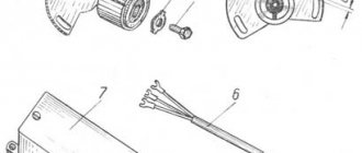
Ignition switch parts
- a) type KZ813;
- b) type 2108-3704005-40;
- Brace.
- Frame.
- Contact part.
- Facing.
- Lock.
- A - hole for the fixing pin.
- B—fixing pin.
The cylinder is connected to a wire and installed inside a wide cylindrical spring, with one edge attached to the cylinder itself, and the other directly to the lock body. Using the spring, the lock can automatically return to its original position after turning on the ignition or after an unsuccessful attempt to start the power unit.
The lock driver can not only rotate the contact unit disk, but also fix the lock in the desired position. Especially for this purpose, the leash is made in the form of a wide cylinder, in which there is a radial channel passing through. There are balls on both sides of the channel, between them there is a spring, with the help of which the balls enter the holes from the inside of the lock body, thus ensuring their fixation.
The contact assembly has two main parts , such as: a contact disk that can be driven and a stationary block with visible contacts. There are plates installed on the disk itself; it is through them that current passes after turning the key in the ignition switch. Basically, up to 6 or more contacts are placed on the block; their outputs, as a rule, are located on the reverse side. Today, modern locks use contacts in the form of plates with a single connector.
The contact group is mainly responsible for starting the starter, the ignition system, and instrumentation; it is located deep in the lock body. You can check its functionality using a special test lamp. But first, before doing this, experts recommend checking for damage to the cables that go to the lock; if any are found, the damaged areas will need to be insulated with tape.
general information
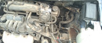
Let's start with general information. You should know that the VAZ 2109 has two power sources - the battery and the generator. The battery is designed to supply current when starting the power unit of a car, as well as to power the starter and other 12 V consumers when the engine is not running. When the engine starts, all the “initiative” goes to the generator. Now this element provides current to all consumers, even the ignition system and battery.
When the generator does not provide current
Note. Every driver must know that if the red charging lamp is on on the instrument panel, then no charge is supplied from the generator to the on-board network, that is, the stored battery energy is consumed. It is clear that the supply is limited and depends on the size of the battery and its capacity. Of course, in this case you can drive home without a generator, but you can no longer turn off the car and you will have to drive non-stop.
Work order
So:
- First of all, you need to check if it is in place. It happens that it breaks off.
- If the belt is in place, intact and undamaged, then it is recommended to check its tension. To do this, press with your thumb from above and notice how much the belt is bent. 10-15 mm is the norm.
- We arm ourselves with the appropriate wrench and unscrew the nut securing the generator to the body. Then we insert the pry bar between the generator and the engine cylinder block. Using the lever method, we move the generator and tighten the fastening nut.
- You need to check whether the corresponding fuse has blown. If yes, then replace it with a new one (more about fuses below).
- We start the power unit and check whether the battery charging lamp goes out. If it goes out, it means everything was done correctly.
- If it does not go out, then you need to check the cable that runs from the generator to the battery (positive). This could be where the problems lie.
Note. There are two wires coming from the battery: the thick one connects the battery to the starter, and the thin one is the one we need.
- We check the integrity of this wire. Maybe it's broken or something.
- You also need to carefully check contacts that may have become oxidized over time.
- All these faults, if found, are corrected. We start the engine and see if charging appears.
- If yes, then have a nice trip!
If there is no charging again, then you need to check the generator itself (see). To do this, it is better to contact specialists or follow the advice that can be found on our portal.
Advice. As mentioned, you can drive with a damaged generator to a service center or your own garage. In order to minimize the battery current consumption, it is necessary to turn off all devices at this moment, such as the car radio, unnecessary lighting fixtures, fan, air conditioner, heater, etc.
Regulator check
If the motorist is experienced, then he can be advised to check the generator voltage regulator. This component is required to maintain the generator voltage within specified limits, even if the speed and load changes. It is possible that it has “worked out” and the generator is not functioning correctly. By car:
- We arm ourselves with a voltmeter equipped with a scale of up to 15-30 V.
- We always measure the voltage after some operation of the engine at medium speed.
- We measure the voltage with the headlights on, in the place between the corresponding terminal and the generator ground. The norm is thirteen/fourteen V.
- Otherwise, if the value is lower or higher, the regulator will need to be replaced.
Checking the removed regulator:
- We dismantle the regulator.
- Let's check it according to the diagram.
Note. If the regulator on a VAZ 2109 was produced before 1996, then it is better to check it together with the brush holder. This will make it possible to immediately detect broken brush leads and poor contact between the ends of the regulator.
- Turn on the test lamp between the brushes.
- We supply a current of 12 V to terminals B and B and the regulator body.
- Then we will double the current, the voltage is already 15 V.
- If the regulator is faulty, the lamp should not light up at a voltage of 15 V and light up at a voltage of 12 V.
- If it lights up in both cases, then the regulator is faulty and you can even accurately determine that there is a breakdown in it.
- If the lamp does not light in both cases, there is a break in the regulator.
Circuit breakers
Fuses are a kind of both defenders and scouts. They are the ones who signal the danger of a short circuit or other electrical problems if they burn out a second time. But electrical problems cannot be put on the back burner, because this threatens to ignite all the electrical wiring and cause a fire.
Note. Remember that it is strictly forbidden to replace a damaged fuse with a new one with a higher rating. Advice. To make troubleshooting easier, it is recommended to use the diagram below.
It is worth noting that different units can be installed on the VAZ 2109: old and new. A distinctive feature of the new one is that it uses fuses of a new type. Instead of cylindrical fuses (as on the old block), blade fuses are used here. In addition, new compact relays are also used in such a unit.
Let us now analyze the fuse diagram for the VAZ 2109, since this is very important for working with the car’s electrical system. We will abbreviate the fuses by the letter P if the mounting block is of an old type and by the letter P if it is new. So:
- 1 and 2 P with 8 A (in the old block) and 8/9 P with 7.5 A (in the new block) are responsible for the fog lights.
- P number 3 with 8A and P1 with 10A - are responsible for the wipers, relays and headlight switch valve.
- P4 with 16A and P7 with 30A - are responsible for headlight cleaners, the electric motor of the heater motor, the rear window wiper gear motor, glove compartment lights, heated glass, etc.
- P5 with 8A and P16 with 15A - are responsible for turn signals, hazard warning relays, taillights, coolant temperature and fuel level indicators, etc.
- P6 with 8A and P3 with 10A - taillights, brake lights and interior lighting.
- P6 and P6 s 30A – are responsible for the front electric windows.
- P7 and P10 with 7.5A - are responsible for the license plate light.
- P8 with 16A and P5 with 20A - are responsible for the sound signal and various relays.
- P9 at 8A and P10 at 7.5A - responsible for the left marker and rear left headlight.
- P10 at 8A and P11 at 7.5A are responsible for the right side marker headlight and the right tail light.
- P11 with 8A and P2 with 10A – are responsible for turn signals and emergency lights.
- P12 from 16A and P4 to 20A - for the rear window heater, cigarette lighter and power socket.
- P13 and P14 with 8A and P15/P14 with 7.5A are responsible for the illuminators/high beams.
- P15/P16 with 8A and P13/P12 with 7.5A - responsible for the illuminators/low beam.
Electrical faults of the VAZ 2109 and their elimination
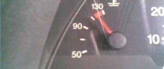
A common electrical problem on the VAZ 2109 is the instrument cluster. It is built into the dashboard on the driver's side and includes a system of instruments that monitor the current condition of the car. These could be devices such as an engine speed sensor or just a series of warning lights.
Let's look at the faults.
Signposts
- If the temperature and fuel level gauge does not work, the cause may be a malfunction of the light bulbs or sensors themselves, or an open circuit in the power supply.
- Treatment: test the entire circuit and check the fuses. If it doesn’t help, then check the functionality of devices and sensors, and then replace them.
Fuel tank arrow
- It also happens that you have just filled up at a gas station, but the indicator arrow returns to the beginning of the scale.
- We check whether the float limiter has been knocked down. It also happens that it is incorrectly installed or adjusted (limiter).
- We remove the sensor and re-adjust.
- If this same arrow constantly jumps and finally drops to the zero mark, the problem is a weak contact of the resistor. There may be another reason: a break in the resistor.
- Treatment: replace the fuel level regulator with a new one.
Light bulbs
- Another popular malfunction associated with the constant burning of this light bulb. The reason may be a short circuit in the sensor itself or its flexible bus.
- Treatment: disassemble the regulator, straighten the busbar and eliminate the short circuit.
Warning lamps
- If the indicator lamps on the instrument panel do not work, then they may have burned out or are loose in their sockets.
- Treatment: lamps are replaced or their contacts are tightened.
- It is possible that the contacts have oxidized. In this case, it is necessary to clean them thoroughly.