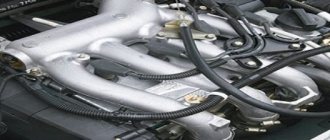
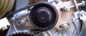
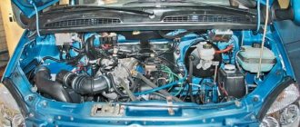
Timing belt
is a closed rubber ring, the diameter of which depends on the type and model of the engine. The inner side of the belt is equipped with special notches along the entire perimeter. That's the whole timing belt diagram. Despite its simplicity, it is impossible for a car to move without it. The purpose of the belt is to connect the camshaft to the crankshaft and synchronize the movement of the pistons with the valves. Since this part is made of rubber, it is practically silent in operation and does not suffer from corrosion. But the timing device is characterized by constant friction between the belt and pulleys, which causes it to wear out and require periodic replacement.
Purpose and types of timing belts
The job of the timing belt is to transmit torque from the engine crankshaft to the fan, gas distribution mechanism, generator and other components, the exact composition of which depends on the car model. The most common at the moment are timing, V-belts and poly-V-belts. Timing belt
is the most complex structurally, but also the most effective.
A broken belt can be a serious disaster for a car engine, since it drives the gas distribution mechanism, and its sudden stop can cause damage to the valves and cylinder head. Before belts, internal combustion engines used chains. Replacing them made it possible to somewhat simplify and lighten the engine, as well as improve its noise characteristics. But the timing belt needs constant monitoring of condition and tension.
Consequences of a broken timing belt
The main task of the timing belt is to connect the camshaft and crankshaft, allowing the valves to open and close in synchronization with the operation of the pistons. The belt should rotate the camshaft at a speed exactly half the speed of the crankshaft. This is important for the normal operation of the internal combustion engine.
If the timing belt
jumps off or breaks, the piston is guaranteed to hit the open valve, bending it, which leads to expensive engine repairs. It should be noted that engines with such design features are installed in the vast majority of cars produced today.
Matching mark matching method
Almost every engine has special marks for adjusting the timing belt. On the pulleys they are made in the form of countersinked holes, and on the engine body itself and the cylinder head they look like a pin, bracket or needle. The essence of this method is that before installing the belt, it is necessary to align the camshaft and crankshaft pulleys strictly according to these marks. It is worth noting that since the timing pulley has half as many teeth, the mark only indicates the beginning of one of the strokes. That is why, for the first time, it may not be possible to adjust the timing correctly: you will need to turn the camshaft pulley one revolution. The exact location and type of marks can be found in the vehicle's operating manual book.
Timing Belt Damage Analysis
Rapid belt wear usually indicates a problem with the timing system. Influencing factors need to be studied and eliminated in order to protect yourself from serious damage.
Defective condition of the timing belt.
- When the timing belt is slightly torn or completely torn and the cord is frayed, then the likely cause of this may be excessive tension
. - If one of the teeth is cut off, this indicates insufficient belt tension.
- The complete absence or significant wear of a tooth on the belt also indicates improper tension.
- A cracked belt surface indicates severe overheating or hypothermia.
- When you can see wear on the surface between the teeth, the belt is most likely not tensioned correctly (too much or too little).
- An oily timing belt indicates that oil is leaking somewhere from the engine. In this case, you need to change the belt and inspect for leaks.
- Noticeable end wear indicates angular or parallel misalignment of the belt.
- Increased noise coming from the belt indicates excessive or insufficient belt tension. This problem should be corrected immediately so that the teeth do not get cut off or the timing belt breaks.
RemBat
arabica2011:
06.04.2016 — 22:25
firstly, first set the flywheel to the 9.6 mark, then open the left hatch where the first injector is from the box and look at how the camshafts are standing, they should look at the upper exhaust spout in your face, looking a little into the cut of the hatch, and the second suction camshaft should look down into your leg, then everything is correct, what if the camshafts are not positioned that way, then turn the crankshaft a full circle to the same 9.6 mark, then you twist the tube onto the fuel injection pump onto the first injector and in the fuel injection pump where you unscrewed the tube into the hole you insert a small nail, not the thinnest so as not to bend and not the longest to put pressure on the valve, but you don’t need to press too hard, then the nail bends, you press lightly so that when you press on the valve you can hear how little it is pressed and with an ordinary hammer with a wooden handle and at the same time you press full throttle and turn on the BCN pump so that you can see how fuel will flow through the pressed nail before this process and at the same time, having unscrewed the special bolt from the flywheel side under the cover, the key there is 27 and it is better to unscrew it with the head 27, then unscrew the corkscrew, carefully pull it out so as not to get caught between the flywheel, unscrew the special bolt clockwise and pull out this bolt and then put in a special key that you can make yourself with such an unnecessary bolt, it is also used on camshafts. to quickly do it, you need to find an unnecessary special bolt and saw off with a grinder the part that spins in the inside, it is unnecessary, and what remains with the splines, grind the outer splines on a sharpener or with a grinder, all the splines so that they don’t interfere with you twisting and rotating the injection pump shaft and weld the form of a bolt or tube to this part, as it will be more convenient for you to twist it at your discretion. And then when you have such a key, press and turn the injection pump pump shaft while pressing the nail with a hammer until the fuel don’t roll and run from the fuel hole where you stuck it in and you need to drive the nail, that’s right, then screw it back counterclockwise with a special bolt, it should match in one position, you can twist it until the internal and external splines match. Don’t forget to use the cotter pins, there are also a lot of them options where it will coincide, in order to pin it, corkscrew everything, not forgetting the nail in the fuel injection pump into the hole) which is unclear, I can tell you. Well, everything should work out for you, there’s nothing complicated. This engine has a TDC, it’s between 11-12, there’s a small square knocked out there, this is for your reference.))
Login to reply
Frequency and reasons for replacing the timing belt
The belt fails without warning and requires periodic replacement. The frequency varies depending on the make and model of the vehicle. This information is provided by the manufacturers in the technical documentation for the machine. Experts recommend changing the belt every 75,000 kilometers. This period may be longer or shorter depending on the current condition of the part.
Visible damage
belt is a clear reason for premature replacement.
It is determined visually: if the belt has not worn out, has not stretched, cracks or other defects have not appeared on it, it will continue to work.
Replacing the timing belt
The timing belt is located at the front of the engine and is clearly visible. In some models it is installed openly, in others it is installed under a cover that protects it and the mechanism pulleys. In modern engines, the crankshaft drives not only the gas distribution system, but also many other devices through a belt. Therefore, the belt follows a complex route and is limited by adjustable rollers to achieve maximum compactness and optimal tension.
Method of enumerating camshaft positions
If the exact position of the marks on the distribution mechanism cannot be established, up to four trials will be required to set it in the correct position. After TDC has been found and the corresponding mark has been applied to the crankshaft pulley, the timing pulley should be turned until it reaches a noticeable stop - the beginning of one of the strokes. After this, the belt is put on and a test is made to start the engine. If unsuccessful, the belt must be removed and the camshaft pulley must be rotated 180° with each test. If the engine starts, but there is strong vibration and inconsistency in the operation of the cylinders, this indicates the opposite clock sequence and the pulley can be turned one revolution at once.
What is a timing belt
The timing belt seems to be the most important element necessary for the correct operation of the machine. It is used to ensure proper synchronization of the crankshaft and camshaft movements. When figuring out what a timing belt is and what its main features are, it is necessary to note its indispensability for supplying fuel to the cylinders of the power unit.
Among other things, the timing belt in a car is used for the proper operation of the fluid pump. It is responsible for circulating coolant throughout the system. This helps prevent engine overheating even under intense loads.
Timing belt
When studying what a timing belt looks like in cars, it should be noted that it is a kind of belt that is located between the cylinder block and the radiator. It should be taken into account that the exact location of this unit directly depends on the specific car manufacturer. In some models it is hidden behind various protective elements, but even in this case it is easily accessible by removing the cover.
If you look at the photo, you can conclude that the timing belt is a closed strip of rubber, equipped with teeth on the inside for better adhesion to the shafts. It must be remembered that such components are intended for use only in a specific model/series of cars and are not universal.
Why is it necessary?
As mentioned earlier, the timing belt is necessary for the correct operation of the engine. It is thanks to him that it is possible to make the operation of the crankshaft and camshaft synchronous. However, often in the design of a car it also serves to perform other actions.
Thus, this unit can be used as a drive for pumping equipment intended for:
- coolant;
- motor oil;
- gasoline/diesel, depending on the type of fuel used.
The timing belt assembly is incredibly important. It is necessary to maintain it in working condition in order to avoid the occurrence of serious problems, the elimination of which will require significant costs.
Operating principle
Having found out how the timing belt is adjusted in a car, it should be noted that it is used to coordinate the operation of the camshaft and crankshaft using special teeth that provide an excellent level of adhesion to the surfaces of these parts.
Moreover, the number of such teeth is strictly limited and depends on the car model used. For example, the VAZ 2112 is equipped with 136 teeth, while other models may have significantly more or less.
Timing chain mechanism
Classification of gas distribution mechanisms
Having found out how the timing belt is deciphered, it is necessary to become more familiar with the existing varieties of such mechanisms. They differ from each other in their characteristics, service life and other parameters. This should be taken into account during operation.
The most common types of timing drive are:
- belt drive. It is characterized by a low noise level during operation, which is compensated by a low level of strength and possible phase shift due to insufficient tension;
- chain mechanism. Thanks to the unique design, the likelihood of phase failure is significantly reduced, which is due to the maintenance of an optimal degree of tension. At the same time, the noise level of this type of drive is much higher, and therefore not all automakers install this element;
- gear drive. This option has been widely used in the past and is characterized by low cost, high reliability and virtually unlimited service life. The disadvantages of such an element include the impressive size of the unit.
Basic engine malfunctions (crank and gas distribution mechanisms)
Let's look at the most common malfunctions of car engines and list the main reasons for their occurrence.
The engine runs erratically or stalls at idle. Main reasons: malfunction of the power supply system, ignition; increased wear of the crank and connecting rod (CVD) and gas distribution (GRM) mechanisms. The engine develops insufficient power. The main reasons: poor filling of the cylinders with the fuel-air mixture; insufficient compression; engine overheating; malfunction of the power supply system, ignition; increased wear of the crank mechanism and gas distribution mechanism; burnout of the head gasket.
Increased fuel consumption and increased toxicity of exhaust gases. The main reasons: malfunctions of the power supply system, ignition and gas distribution mechanism.
Smoky exhaust. The main reasons: with a black exhaust - over-enrichment of the mixture, with a blue exhaust - combustion of oil in the exhaust system due to an increased level in the engine crankcase or wear of the cylinder-piston group.
Silenced shots. The main reasons: loose closure of the exhaust valve or its burning; rich mixture.
Popping sounds in the intake manifold. The main reasons: loose closure of the intake valve; lean mixture.
Increased oil consumption. The main reasons: wear or coking of the piston rings; wear of pistons and cylinder walls, oil seals and valve guides; crankcase ventilation system clogged.
Insufficient engine oil pressure. The main reasons: wear of the main and connecting rod journals and crankshaft bearings; lubrication system malfunctions.
Knocks and noises when the engine is running. The main reason: wear of parts of the crank and gas distribution mechanisms of the engine.
Causes of breakdowns
The most common failures of this unit seem to be a phase break or loss. This leads to engine stoppage and serious damage requiring expensive repairs. The most likely causes of breakdowns include excessive wear, jamming of the tensioner pump or shafts, as well as insufficient tension.
Ways to eliminate them
The troubleshooting procedure is significantly different and depends on the cause of its occurrence. Most often, the belt needs to be tensioned to its optimal condition, which can be done using an appropriate mechanism. However, if there is a break or other serious damage, the timing belt may need to be replaced.
The procedure is quite simple and involves the following steps:
- Remove the front wheel to gain access to the crankshaft pulley.
- Remove the power steering belt, alternator, spark plugs and pump mechanism.
- Remove the pulley and the right engine support.
- Remove the worn timing belt and install a new one in its place.
Next, you will need to repeat all the operations in reverse order, installing the dismantled components on the car one by one. Thanks to its simple design, such manipulations can be done with your own hands, significantly saving on the services of specialists.
Why do you need to adjust the timing chain?
Chain adjustment is an integral part of any car (But we will consider VAZ 2101, 2106, 2107, 2109 and 2114). Because the chain is very important to the engine. Due to the timing chain, the engine rotates evenly and does not create problems when driving. But over time the car is used, the chain begins to loosen. In connection with this, a number of problems arise, which are described below in the section “What will happen to the engine if the chain adjustment is disrupted?”
What will happen to the gas distribution mechanism if the chain is not adjusted?
Due to incorrect adjustment of the chain, the setting of the valve timing may be disrupted, which in turn is very fraught with improper operation of the engine, and also due to poor adjustment of the chain, the wear of the sprockets on which it is installed increases.
What is a timing belt in a car?
Timing mechanism stands for gas distribution mechanism. Its purpose is to supply the air-fuel mixture (AFM) to the cylinders at a certain frequency, and also to remove exhaust gases from the cylinder chambers. Instead of VTS, simply air can be supplied, it depends on the design of the engine in the car. The engine will perform its functions if the valves open and close in time and the pistons move correctly in the cylinders.
Gas distribution mechanisms differ in the type of drive coming from the crankshaft. It can be chain or belt.
The timing differs in the location of the camshaft in the car:
- The valves may be located on top of the cylinder head, and the camshaft inside the cylinder blocks. Thanks to the valves, the rocker arms and push rods are driven. The advantage of this system is its simple design and correspondingly high reliability. The disadvantage is great inertia, which does not allow you to gain high speeds, which reduces power.
- With the valves located at the bottom, they are located from the bottom with the plates facing up. The camshaft is located below and the drive comes directly from it. The advantage of this system is low noise and ease of manufacture. The downside is that the fuel system has a complex system, because of this the power drops, as there is poor saturation of the chambers with high-quality VTS.
- A type of timing belt are engines in which the camshaft is located in the cylinder head along with the valves. There are engines in which the valves are located on both sides of the camshaft and are driven by rocker arms strung on one axis. Rocker arms swing the cams on the camshaft. The disadvantages of the system include high noise and complexity of valve clearance settings, as well as a large load at the contact points.
- There are systems where the camshaft is located above the valves, the valves of which are located below. With this design, the camshaft moves the valves using cylindrical pushers. The disadvantage of the system is the low elasticity of the engine and the difficulty of adjusting valve clearances. These systems, in turn, are divided into two types according to the number of valves per cylinder: two and four.
Timing device of an internal combustion engine
What does the timing belt have to do with it, what is it anyway?
So, the hero of today’s article is the element that rotates the cam shaft of the gas distribution mechanism, forcing this system to perform its functions. In addition, through this belt drive, other engine components can be driven in parallel, such as: a cooling circuit pump, an oil pump, etc. Rotation is transmitted to the belt itself from the engine crankshaft, the movement of which is the result of engine operation.
What is the timing belt used for?
Now let’s figure out what a timing belt is and what its operating principle is. Its main purpose is to connect the camshaft and crankshaft.
Purpose and principle of operation of the device
The timing drive is a rubber product with a toothed inner surface. Made from durable rubber, it fits over the crankshaft and one or more camshaft gears. The purpose of the teeth is to provide good grip and prevent slipping. Their number is strictly defined, since the synchronization of the crankshaft and camshafts depends on it. For example, on VAZ-2111 and VAZ-2112 engines, camshaft belts with 111 and 136 teeth, respectively, are installed.
Timing belt
The camshaft wire is an important component of the car, so you should understand what a timing belt is and constantly monitor its condition. Replacement should be carried out according to the regulations after 30-45 thousand kilometers or if its parts are damaged. If the replacement is not done in a timely manner, the belt may break, which will lead (at best) to stopping the car, or at worst to a breakdown of the internal combustion engine and its overhaul or replacement. The reason for this is that when the belt breaks or comes off, the synchronization of the shafts disappears, as a result of which the pistons begin to hit the valves. Since this most often happens at high speeds, components quickly become unusable.
Proper operation of the engine can extend the service life of the engine. You should not start the engine by towing; it is at these moments that there is a high probability of the timing belt breaking and slipping off, which leads to breakdown of the power unit. It is cheaper to find and eliminate the cause of the problem, or call a tow truck, than to overhaul the power unit. In addition to synchronizing the shafts, the belt can serve as a drive for the pump:
- coolant;
- oils;
- high pressure fuels, etc.
The proper functioning of the engine in the car depends on the proper functioning of the timing belt and the timing belt, so you should monitor the condition of the gas distribution system: observe routine checks and promptly replace components that have become unusable.
Explanation of timing belt symbols
Decoding the timing belt designations according to international standards can be considered using the example of a belt for a VAZ-2111 power unit. These engines are equipped with an ISO-58111×19 belt. The first two digits - 58 - contain an encrypted series of teeth. In the case under consideration, the pitch and profile are without a groove, semicircular in shape with a height of 3.5 mm. The next numbers - 111 - indicate the number of teeth. The X is followed by the number 19, indicating the width of the belt. There may be teeth in the shape of a rounded trapezoid (involute). They can be completely replaced by those described above.
Many timing belt manufacturers do not indicate the ISO designation, but a number that corresponds to their own catalog. Below is a table with designations and brief characteristics of belts from different manufacturers.
Dayco timing belt
| Manufacturer | Belt designations | ||
| ICE 8V | ICE 16V | ||
| Contitech | CT 527 | CT 996 | The brand's belts are supplied to many countries around the world. They can be installed on both domestic and imported brands of cars. |
| Bosch | ZP 1 987 949 095 | ZP 1 987 049 559 | Reliable, low noise, they ensure synchronous transmission throughout the entire service life. They have wide application. |
| Gates | 5521 | 5539 | The company has been on the market for more than 100 years, offering a wide range of drives for both foreign and domestic cars. |
| Dayco | 111 SP 190 EEU | 136 SP 254 H | The belts have high wear-resistant qualities. The company has been supplying leading companies with products for primary equipment for 40 years, so it has an impeccable reputation. |
Not only the geometric parameters are important, but also the performance characteristics of timing belts. Belts must be:
- tear-resistant;
- reliable;
- the connection to the base must withstand operation over a wide temperature range;
- the operating time must be maintained until complete wear;
- After operation, there must be an acceptable elongation.
Thus, you should use belts from trusted manufacturers that have high quality and long service life.
Installation for checking and adjusting engine timing
The installation for checking and adjusting the timing belt consists of a crankshaft cranking mechanism and a lifting table (Figure 3). The mechanism for cranking the crankshaft includes an electric motor 1 with a control circuit, a gearbox 2, a chain transmission 3, on the driven sprocket shaft of which a nozzle 5 is attached using an elastic coupling 4, which engages with a ratchet on the crankshaft. Sensor 6 is located at the other end of the output shaft.
The lifting table consists of a table 7 and a frame 8, connected by two pairs of levers 9 and 10. Levers 9 and 10 are hinged at one end, respectively, to the table 7 and frame 8. At the other end of the levers, sliders 14 are hingedly attached using movable axes 15 and 16, which move in the guides of the table and bed. In the upper axis 16 there is a threaded hole into which a screw 17 of the screw mechanism for lifting the table is screwed.
The table is raised and lowered using a screw mechanism, which changes the distance between the ends of the levers 9 and 10. To facilitate movement of the device, one side of the frame 8 rests on two wheels 19.
The electrical diagram of the device is shown in Figure 4.
The crankshaft cranking mechanism is driven by an asynchronous three-phase electric motor with a supply voltage of ~ 380 V. The electric motor power control circuit includes a magnetic starter MP, a protection relay P with normally open contacts P1, a sensor with normally closed contacts D1, an operating mode switch B1, and the “Start” buttons. and "Stop".
When you press the “Start” button, relay P is turned on, contacts P1 closing the power circuit of the coil of the MP magnetic starter. Current flows through the electromagnet winding of the MP magnetic starter, the magnetic starter is triggered and the MP1 contacts turn on the electric motor.
To stop the electric motor, use the “Stop” button, which breaks the power supply circuit of relay P, which then turns off the magnetic starter MP. The electric motor is turned off by the contacts of the MP magnetic starter.
To stop the output shaft in a strictly specified position, a sensor is provided, the moving contact of which is acted upon by a cam mounted on the output shaft of the device. The number of vertices is equal to half the number of cylinders in a car engine. When the contacts of sensor D1 are opened, the power supply to relay R is turned off.
For proper operation of the device control circuit, it is necessary that the contacts of sensor D1 open at a moment that ensures that the output shaft of the device and the engine crankshaft stop when the piston of the corresponding cylinder reaches top dead center. The setup is carried out as follows. Switch B1 is set to the “Settings” position. In this position, contacts B1 are closed, relay P is powered regardless of the position of the output shaft and the state of contacts D1. Pressing the “Start” button turns on the device. Using the marks, the piston of the first cylinder is set to the position corresponding to the top dead center of the end of the compression stroke, and the “Stop” button turns off the device. The sensor body is rotated until the marks on the body and rotor are aligned, which ensures the open state of contacts D1. The sensor housing is fixed. Switch B1 is set to the “Operation” position. Now, when contacts D1 are opened, relay P is turned off, which turns on the magnetic starter MP, and the electric motor stops.
To set the piston of the next cylinder in the operating order to top dead center, you must press and release the “Start” button. When the output shaft is rotated at a given angle, contacts D1 open, relay P is turned off, contacts P1 turn off the magnetic starter, which turns off the electric motor with contacts MP1.
Three-phase electric motors, if one of the phases is accidentally disconnected, quickly overheat and fail if they are not disconnected from the network in time. In this circuit, motor protection is implemented as follows. If line wires B or C are broken, relay P is switched off; if wire A or C is broken, the magnetic starter of the MP is switched off. In both cases, the electric motor is turned off by the contacts of the magnetic starter.
As a result of the introduction of an installation for adjusting the gas distribution mechanism, operating costs are reduced. The total annual savings amounted to 14,332.93 rubles. Net present value – 89,175.96 rubles. The profitability index was 14.8. The payback period for the investment will be 0.4 years.
Installation for checking and adjusting engine timing General drawing
Lifting table Assembly drawing
Kinematic and electrical installation diagrams for checking and adjusting engine timing
Details of the installation for checking and adjusting the engine timing belt
Drawing The influence of the thermal gap in the timing belt on engine performance
Drawing Technological process for manufacturing the part Lower finger
3 DESIGN PART
3.1 Justification for the need to develop the design
3.2 Description of the proposed design diagram
3.3 Calculation of the adaptation mechanism
- 3.3.1 Calculation of the crankshaft cranking mechanism
- 3.3.2 Calculation of the lifting mechanism
- 3.3.3 Development of a technological process for manufacturing the “finger” part
3.4 Operating instructions for the device
4 ECONOMIC PART
4.1 Calculation of the cost of a stand for adjusting the gas distribution mechanism
4.2 Calculation of technical and economic indicators
4.3 Evaluation of investment projects
Explanatory note 35 pages of description and calculations, specifications.
Tags: Installation of checking engine timing adjustment
