Cummins engines run on diesel and are quite popular around the world. In Russia, motors of this brand already have many fans, as they are ideal for trucks and other commercial vehicles, electric and pumping stations, etc.
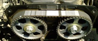
Since 2010, the domestic manufacturer GAZ has been producing Valdai brand trucks based on Cummins ISF 3.8 engines. This is a four-stroke engine that runs in the order 1-3-4-2. It has a one-piece cylinder head with 4 valves per cylinder.
Cars with Cummins engines attract buyers due to their simple design and repair. Any diesel engine specialist can easily understand Cummins engines and carry out both maintenance and major repairs.
Valves on a Cummins engine
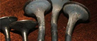
The diesel engine has intake and exhaust valves, which are made of heat-resistant steel. Their rods are chrome plated to prevent scuffing. The valves are designed identically, but are not interchangeable.
Each valve has a spherical well, and the outlets are engraved with the letter "C". The springs of the latter are reinforced and made of chrome-silicon compound.
The valves are located on the cylinder head - two valves per cylinder. The combustible mixture is admitted through one of them, and exhaust gases exit through the other. And the names of the valves are appropriate - intake and exhaust.
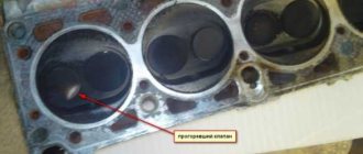
The valve head contacts the valve seat up to 70 times per second during operation. The exhaust valve becomes especially hot at this time, since the gas temperature at the outlet can reach 800°C.
The valves are driven by a gas distribution or valve (as drivers are more familiar with it) mechanism. The engine heats up during operation, causing its parts to expand. Therefore, in a cold state, there must be gaps of a strictly defined size between them.
A car thermostat is a device that regulates the temperature of the fluid in the engine cooling system. This device is located in the flange between the radiator and the engine.
The new generation of Kamens oil pressure sensors are capable of performing not only a monitoring function. Their use makes it possible to improve the functioning of the engine itself. Read more about sensors here.
Problems with the cylinder head on the engine can occur if the vehicle is used incorrectly or if low-quality parts are installed. Also, if maintenance is untimely, the following breakdowns may occur:
- valve mounting parts;
- camshaft;
- valve lifters;
- Cummins valves;
- head gaskets, etc.
If the engine overheats, the cylinder head may crack and will need to be replaced. You should monitor this part, do maintenance on time and use Cummins consumables.
Gaps
Here is the combustion chamber of an ordinary Chinese scooter engine.
During engine operation, the valves heat up to significant levels. And in order to compensate for the expansion coefficient of the valve and the entire timing belt as a whole, there is a small gap between the valve and its opening mechanism. Called thermal.
In our case, the gap that we will adjust is between the valve and the rocker arm adjusting bolt. By tightening the adjusting bolt within the required limits, we can adjust the thermal gap as much as we need.
But do not forget that the gap should not be very large - otherwise the mechanism will work with a shock load and quickly fail. And very small: the valve will heat up, hit the rocker arm and burn out.
The need to adjust Cummins ISF 3.8 valves
A diesel engine requires periodic checking and adjustment of valves. For comparison, in gasoline engines the condition of the valves is maintained by hydraulic gap compensators, which are absent in diesel engines.
Therefore, it is recommended to adjust the valves on the cylinder head after every 120 thousand km traveled by the car.
During operation, valve clearances may increase, which directly affects compression in the engine. Knocks may appear during engine operation, seats may fly out, engine power may become lower, and fuel consumption may increase.
If the seats fly out, the cylinder head will have to be repaired or replaced. Valve knocks can reach the piston, which will lead to the need to replace it. And if the gaps between the valves are very small, this will lead to burning of the seats.
Therefore, the valves of Cummins ISF 3.8 engines should be adjusted on time, and during heavy use - every 70 thousand km.
Even if the recommended mileage is unknown, but a knock is heard in the engine or the quality of its operation has decreased, then you need to start by checking the valves.
You can entrust this procedure to specialists at a service station, or you can do it yourself, since this operation is not so complicated.
Adjusting valves on FORD cars
Depending on the engine model on Ford cars, adjustment can be done using both adjusting washers and screws. Washers are installed on modern motors of the Zetec series, on many Duratec models. On older Ford models such as Sierra, Granada, etc., the valves are adjusted by screws.
On Ford Focus or Mondeo cars, RK is performed as needed (after about 150 thousand km), this work is not included in the maintenance regulations. For intake valves, gaps are set at 0.17-0.23 mm, for exhaust valves - 0.31-0.37 mm.
RK on the Zetec-E internal combustion engine of Ford Focus cars is labor-intensive work; to replace the washers, you will need to remove the camshafts (DOHC engines). It is better to carry out such work in a car service center and trust the adjustment to mechanics with sufficient experience. It should also be taken into account that over time the valves do not begin to knock, as the seats gradually wear out. Therefore, you should check the gaps more often, say, every 80-90 thousand km.
PRTZK - according to the order of operation of the cylinders 1342.
Self-adjustment of Cummins valves
Valve adjustment is done only on a cold engine. First you need to unscrew the valve cap. To do this, remove the breather tube, secured with a clamp. You need to disconnect the high pressure pipes from the injectors using keys 13 and 17.
To move the fuel rail to the side, you need to loosen the nuts. To remove the injectors, you should first pull out the clamps of the return fittings with a screwdriver. Next, you need to disconnect the power connectors from the injector. Only after this can you unscrew the lock of the nozzle itself and pull it up. The same steps should be performed for the next three injectors.
Each injector has its own identification number, programmed in the engine control unit. For this reason, you should mark where each injector is inserted, otherwise the operation of the motor may be uneven if these parts are mixed up (it is worth noting that visually they are the same).
It is necessary to pay attention to the spray head - if it is clogged, then it can only be cleaned with special solvents and a lint-free cloth, but under no circumstances should it be mechanically cleaned.
The valve covers are made of plastic and are attached with bolts that can be easily unscrewed. Now you can start adjusting the valves. It is necessary to set the piston of the adjustable cylinder to top dead center.
To do this, the hole in the crankshaft pulley should be aligned with the hole on the engine block at the top point of the pulley. You only need to turn the crankshaft clockwise using the crank handle or the pulley mounting bolt. In this position, both cylinder valves are closed, and their rocker arms swing freely within the clearance.
Externally, it is visually noticeable that the intake valves are shorter and the exhaust valves are longer. When adjusting, you need a set of feeler gauges: 0.30 mm for inlet and 0.51 mm for outlet.
The general procedure for adjusting the gaps, as during engine operation: 1-3-4-2. After adjustment, you should check the gaps between the valve stems and rocker arms. The maximum gaps for the intake valve can be 0.33 mm, and for the exhaust valve - 0.584 mm. This can also be checked by eye.
The valves should fit optimally - neither too tight nor too loose. Once the adjustment is complete, the mechanism is assembled in the reverse order.
With proper adjustment of the Cummins ISF 3.8 valves, the sound of the operating engine will be smooth and without unnecessary noise.
Procedure for adjusting valve thermal clearances
Almost all internal combustion engines of modern cars have a right-hand rotation of the crankshaft - the crankshaft rotates clockwise. The camshaft is driven from the c/shaft, and rotation is transmitted to the camshaft through a belt or chain. There can be several camshafts in an engine; how many there are in an engine depends on the design features of the power unit.
Each camshaft (CV) must have cams, which ensure the opening and closing of the valves and the filling of the internal combustion engine cylinders with the air-fuel mixture. In order for compression to be created in the cylinders, the valves in the cylinder head must be tightly sealed against their seats at the moment of closing.
There must be a thermal gap between the valve and the RV cam; it is measured when the valve is completely closed and the R/shaft cam does not press on the valve. For normal operation of the cylinders, the valves must be adjusted in accordance with the recommendations of the engine manufacturer, and each internal combustion engine model has a certain procedure for adjusting the valve thermal clearances (VTRZK).
PRTZK depends on:
- on the number of cylinders in the engine;
- cylinder operating order;
- specific engine model.
For example, the order of operation of the cylinders for many Russian internal combustion engines:
Currently reading
Installation and repair of the muffler resonator
How often to change the timing belt on a car: what you need...
- four-cylinder – 1342;
- six-cylinder – 153624;
- eight-cylinder - 15426378.
But not all 4-cylinder internal combustion engines operate in the order indicated above, for example, the ZMZ-24/402 and UMZ-414/417/451 engines and some of their other modifications operate in the order 1243. Eight-cylinder V-shaped engines of the German concerns Audi/Volkswagen, BMW and Mercedes have a cylinder operating order of 15486372. It should be noted that passenger cars also have 2, 3, 5 and 12 cylinder internal combustion engines, respectively, they have their own cylinder operating order. The valves on the engines can be adjusted in different ways:
- for each cylinder when the piston in it is at TDC (top dead center);
- for two revolutions of the crankshaft (in the TDC positions of two cylinders, for example, for a 4-cylinder engine - the first and fourth).
Cummins ISF 3.8 cylinder head malfunctions
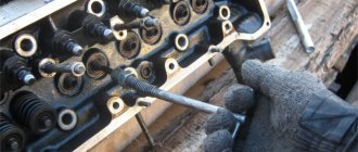
Most often, problems with the cylinder head can arise from valves. Therefore, first you need to remove the valve cover and inspect all the parts. The first thing that may happen is that the valve pusher or valve spring may break. If everything is in order with the valves, then you should remove the head from the block and begin repairs.
Next you need to drain all the coolant and remove the fuel injectors. If they are clean, then simply remove them, but be sure to remember the location of each part. If the nozzles are dirty, they should be washed thoroughly. The removed cylinder head must also be washed very well.
When replacing valves with new ones, they should be ground in to ensure maximum tightness. Loose valve fit reduces compression - one of the important indicators of Cummins ISF 3.8 diesel engines.
The support cushion is made of rubber and metal, since in addition to the engine mounting itself, the design includes a support that supports the gearbox. The main function of the design is to maintain engine performance and minimize vibrations of the mechanisms located in it.
Like any element of a vehicle engine, tension rollers have a number of advantages that affect the improvement of vehicle performance, and certain disadvantages. Read about everything related to tensioners here.
If there are problems with valve adjustment, the cause may be wear formed on the camshaft cams. Replacing this part will restore the operation of the gas distribution mechanism, and this will reduce fuel consumption and increase engine power. After replacing the shaft, the valves must be adjusted.
Extending the life of a Cummins cylinder head can be quite simple - undergo timely maintenance and use only high-quality Cummins spare parts and consumables.
There are a lot of parts in the cylinder head that should be lubricated regularly. Poor quality oil will lead to rapid wear and frequent breakdowns.
It is also necessary to monitor the serviceability of the oil filter, since its clogging can lead to poor quality of even good oil and, as a result, rapid wear of parts.
Thus, in order for Cummins ISF 3.8 engines to work for a long time and their parts not to wear out so quickly, it is necessary to constantly monitor the condition of the cylinder head and, especially, the valves on it, which need to be adjusted from time to time.
Tools
- Small pliers or special wrench
- Open-end wrench 9
- 14mm socket wrench or socket
- Socket wrench 8
- A set of measuring probes, preferably with a pitch of 0.02 mm
We free access to the cylinder head: depending on the scooter model, we remove the hood or seat tank. We find the valve cover there, unscrew the four 8mm bolts and remove it from the engine.
The valve cover looks like this. In my case, to get to it I had to remove the hood, saddle and seat tank.
There is a generator casing on the right side of the engine - remove it. If you are too lazy to remove it, just take out the plug. The plug is located in the upper part of the case and can be removed using a regular screwdriver. Through the plug we will control the position of the marks on the rotor.
We insert a 14 mm socket wrench into the center of the generator casing and turn the engine (clockwise) until the “T” mark (from the English “Top” means top, in our case the piston position is at TDC) on the generator rotor is exactly opposite the ledge.
After the mark on the generator coincides with the ledge on the engine crankcase, we check what position the camshaft is in. The camshaft should be in a position where both valves are closed. And it gets into this position every second revolution of the crankshaft since it rotates twice as slow.
The correct position of the camshaft is determined by its sprocket. The sprocket should become the large hole facing up, and the small holes and the marks that are knocked out near them should become parallel to the plane of the valve cover connector.
This is ideal, but in practice the asterisk rarely becomes the way we need it. And the chain is often to blame for this - it stretches and the camshaft begins to slightly not catch up with the crankshaft. If your sprocket has become a little crooked, then by and large it’s nonsense. But if you have it for some reason, then this problem needs to be solved very quickly - otherwise sooner or later the valve will bend.
Once again, check that the “T” mark on the generator rotor is opposite the protrusion, and that the camshaft sprocket is in the correct position. Unscrew the locknuts on the adjusting bolts.
We unscrew the adjusting bolts a little, insert a measuring probe between the valve and the adjusting bolt and, without removing it, tighten the adjusting bolt with our fingers, clamp the adjusting bolt with pliers and secure it with a lock nut.
After tightening the locknut, check how easily the dipstick moves. Ideally, the feeler gauge should move between the valve and the bolt with barely perceptible force.
- If the dipstick moves without effort, loosen the locknut and tighten the bolt a little.
- If the dipstick moves with difficulty or becomes jammed, loosen the bolt.