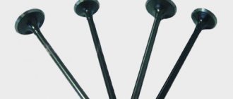
Engine model
The most powerful engine of all that was installed on the “ten” is the injection 16-valve VAZ-2112 with a volume of 1.5 liters. However, this power unit has one drawback: if the timing belt breaks, the pistons meet the valves, which leads to serious and expensive repairs of the power unit. And high-quality repair and maintenance of VAZ-2110 injection engines requires special diagnostic equipment. Often, a malfunction of just one sensor leads to unstable operation of the entire engine.
Add a comment Cancel reply
You must be logged in to post a comment.
The 16-valve VAZ-2112 engine was at one time the most dynamic and responsive engine in the VAZ lineup, which made it both the most popular and difficult to repair and maintain. In this article we will tell you in detail about the design of this engine, its advantages and disadvantages.
Electronic Component Compatibility
Since the controllers were produced by different manufacturers, many of them differ not only technically, but also commutatively:
- They have their own connector that is not compatible with other controllers;
- They differ in the number of contacts and wires;
- They have different mode algorithms (no hardware compatibility);
- Controllers of recent years have built-in switches, while earlier models were built on ignition modules.
In particular, Bosch MP7.0:
- originally created for LADA 110 cars sold in foreign markets;
- has a 55-pin connector;
- does not contain either software or hardware compatibility with other units;
- is able to work after modernization on other types of ECM.
Other controllers such as Bosch M1.5.4, VS 5.1 and January 5.1:
- are software incompatible with each other;
- have different firmware;
- but they can replace each other (in this case the engine operation algorithm will change).
For reference: each controller has its own hardware implementation of the fuel injection algorithm. Most often, one of three is implemented: either simultaneous injection, or phased or pairwise - parallel injection.
Each injection algorithm has its own characteristic features:
- equipped with a special ECU;
- flashed with a specific software version;
- Comes with separate wiring.
Schematic sketch of the VAZ-2112 engine
Detailed diagram of the VAZ-2112 engine.
1 – engine sump. 2 – front crankshaft oil seal. 3 – crankshaft. 4 – crankshaft pulley. 5 – oil pump. 6 – generator drive pulley. 7 – timing belt. 8 – front cover of the timing mechanism drive. 9 – coolant pump pulley (pump). 10 – tension roller. 11 – camshaft toothed pulley. 12 – rear cover of the timing mechanism drive. 13 – camshaft oil seal. 14 – exhaust camshaft. 15 – hydraulic pusher. 16 – valve spring. 17 – valve guide sleeve. 18 – exhaust valve. 19 – receiver. 20 – camshaft bearing cover. 21 – guide pipe. 22 – cylinder head cover. 23 – plastic cover. 24 – spark plug. 25 – intake camshaft. 26 – inlet valve. 27 – cylinder head. 28 – coupling. 29 – fuel rail. 30 – crankcase ventilation hose. 31 – nozzle. 32 – intake manifold. 33 – flywheel. 34 – crankshaft rear oil seal holder. 35 – rear crankshaft oil seal. 36 – cylinder block. 37 – oil dipstick. 38 – piston. 39 – connecting rod. 40 – connecting rod cover. 41 – crankshaft main bearing cover.
just about the complex » AutoNovator
An important warning for drivers who are just learning the principles of a car and are trying to repair components and mechanisms with their own hands. Do not confuse concepts such as cylinder numbering and firing order.
What determines the numbering of engine cylinders?
However, it is important to know that whatever the engine layout and cylinder arrangement, cylinder No. 1 - the main cylinder, always contains spark plug No. 1.
Naturally, this is the order in which the cylinders of any engine are numbered. What determines the location and numbering of engine cylinders:
- drive type: front or rear;
- engine type: in-line or V-shaped;
- engine installation method: transverse or longitudinal;
- direction of motor rotation: clockwise or counterclockwise.
The arrangement of cylinders in multi-cylinder engines is as follows:
- vertically - that is, in one row, without angular deviations;
- obliquely – at an angle of 20°;
- V-shaped - in two rows. The angles between rows can be 90 or 75 degrees;
- opposite (horizontal) – the angle between the cylinders is 180°. This arrangement of cylinders is used in bus engines, which allows the engine to be placed under the floor of the passenger compartment, freeing up usable space.
Numbering of cylinders on different types of engines
As such, there is no strict international system for the location and numbering of engine cylinders. And that's bad. Therefore, before you begin any type of repair of the engine or ignition system, immerse yourself in the Operating and Repair Instructions for your particular car.
Rear-wheel drive 4- and 6-row engines in the USA have a master cylinder number 1 from the radiator, the remaining cylinders are numbered towards the passenger compartment. But there is also reverse numbering, when the master cylinder is considered to be the one closest to the passenger compartment.
For French engines, cylinder numbering occurs on the gearbox side. And the numbering of the cylinders of V-shaped engines comes from the right side, i.e. on the torque side.
Front-wheel drive cars typically have a transversely mounted engine. Here the cylinders are numbered on one side, and cylinder No. 1 is located on the passenger side.
V-twin multi-cylinder engines have the driver's side master cylinder in the bank closest to the passenger compartment. Then there are the odd-numbered engine cylinders, and on the opposite side (closer to the radiator) there are the even-numbered ones.
Therefore, in order to ensure that you are not completely confused due to the lack of a unified international standard for the location and numbering of engine cylinders, use the manufacturer’s Operating Manual.
Good luck learning the numbering and arrangement of engine cylinders.
Engine device
16-valve 124 engine under the hood of a “two-wheeler”
- The engine is a sixteen-valve, in-line, four-stroke gasoline engine, consisting of four cylinders. The operating order of the cylinders is: 1-3-4-2 – starting from the crankshaft pulley. With a power supply system – distributed injection, controlled via a Bosch, “January” or GM controller.
- The engine is secured in the engine compartment using four elastic supports, of which the front and rear are rods that are fixed from the engine to the body, and the left and right are identical to the VAZ-2110(11).
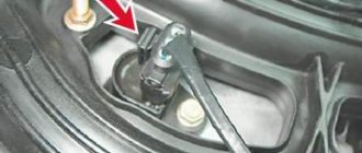
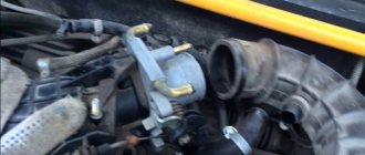
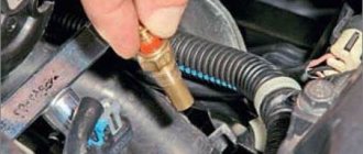
- On the engine, on one side there are camshaft and crankshaft drives, a coolant pump (about checking the pump and choosing a pump - note), a generator, as well as a timing belt (about replacing it here), on the other side there are sensors: coolant temperature, pressure oil, starter, thermostat, front: ramp with injectors, intake manifold, oil dipstick, knock sensor, crankcase ventilation hose, phase sensor. On the reverse side: oil filter, crankshaft position sensor, exhaust manifold. Top: spark plugs, high-voltage wires. More details about all sensors are written here.
- The cast-iron cylinder block has the same index “21083” with engines from the VAZ-2110 (11), however, they have different screws for the cylinder heads M10x1.25 in contrast to M12x1.25, as well as their smallest entry depth.
- Each engine has its own serial number.
Types of controllers
The constant search for a software package capable of fully controlling the operation of the power unit in accordance with EURO 3 standards could not but affect the technical configuration of the car.
This has led to the fact that different controllers are installed on VAZ 21103 cars of different years of manufacture:
- January 5.1.x;
- Bosch M1.5.4;
- Bosch MP7.0;
- Bosch M7.9.7;
- VS 5.1.
Bosch M7.9.7 controller with serial firmware B104CR02
For reference: the manufacturer must indicate the installed firmware version on the controller. You can see it if you open the case with your own hands - its factory index is on the label under the barcode.
Basic information about the injector circuit
The VAZ injection system is designed quite simply and contains practically no nuances specific to understanding. A novice motorist even knows the general principle of operation of injection systems. Elements of the injection system and their basic functions:
- the fuel regulator is located on the injector, the latter, in turn, is located on the frame to which fuel is supplied using a pump (all the fuel first passes through a specialized filter);
- the fuel pressure should not exceed 300 mPa, therefore, if any excess fuel occurs, it is sent back to the tank using a membrane regulator;
- the bypass valve controls the position of the diaphragm, which in turn is subject to triple pressure: the pressure of the fuel itself, as well as the intake air and the corresponding spring;
- the fuel regulation scheme described above directly depends not only on the current engine load, but also on the throttle position;
- the cylinder is filled with fuel during rotation of the crankshaft, the volume of incoming fuel is determined by the position of the injector (see), which is directly controlled by the controller.
The role of the injector and controller in the overall injector circuit
- the position and opening time of the injector determines the volume of fuel that enters the cylinders;
- special sensors are installed on the engine that transmit relevant information to the controller;
- the controller, based on information received from the engine, sends an electrical pulse of a certain length, which determines the duration of opening of the injectors;
- when starting the engine, the controller is in asynchronous operating mode until the engine itself reaches 400 revolutions in one minute;
- injectors may temporarily not function in the event of braking or if the engine is in purge mode;
- if the engine operates in high load mode, then the air information signals transmit the corresponding electrical impulse to the controller, which in turn sends the corresponding signal to the injectors taking into account the current speed of the car;
- Thus, in the injector circuit, the controller is a regulating element, and the injectors are an executive element.
The role of the electronic control unit in the overall injector circuit
From a practical point of view, the electronic control unit consists of several high-tech components: ROM - memory devices, PROM - dynamic memory devices, RAM - regulatory memory (all of the above elements function only if there is voltage available).
Note. The electronic control unit is actually a microprocessor, so even an experienced motorist is simply not able to repair it, since specialized knowledge from the relevant higher school is required.
- all engine parameters, together with the microprocessor operating program, are stored in ROM;
- RAM is a random access memory, which is a temporary source of information storage, and each new start of the microprocessor leads to a complete clearing of intermediate information;
- all information coming from the sensors to the controller is not only analyzed, but also stored; at the same time, the controller itself carries out diagnostics of the information sensors from time to time;
- Ignition and injectors are the main functional elements of the injection system, subordinate to the controller.
Note. There is a “CHECK ENGINE” warning light on the dashboard; if it lights up, it means that the controller is in a faulty state or there has been some malfunction in its operation.
Crankshaft position sensor (CPS)
Often the engine stalls due to problems with the DPKV. To check, you will have to remove this sensor from the engine. Be sure to mark its position on the engine.
After removal, you need to measure the resistance of the sensor inductive coil. The multimeter should show a resistance between 550 and 750 ohms. Anything more or less indicates a sensor malfunction. It needs to be replaced. There are other testing methods, but they are “difficult to apply” in a regular garage.
Now a short video with another reason.
How does an injector work?
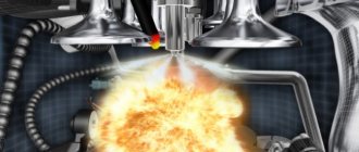
Fuel supply with distributed injection in VAZs has its advantages. Basically, it saves fuel consumption and speeds up engine operation. The gasoline injection process is regulated by an electric pump, which closes and opens the injector valves, ensuring the supply of gasoline. The functioning of the electronics occurs due to signals from system pressure sensors and air sensors
. The absence of this part increases fuel consumption on the 8-valve VAZ 2110 (carburetor), after which many change their minds in favor of Lada injector models.
Fuses and relays 2112
Fuse number Current strength, A Protected circuits
- F1 5 License plate lamps. Instrument lighting lamps. Side light indicator lamp. Trunk light. Left side marker lamps
- F2 7.5 Left headlight (low beam)
- F3 10 Left headlight (high beam)
- F4 10 Right fog lamp
- F5 30 Electric door window motors
- F6 15 Portable lamp
- F7 20 Electric motor of the engine cooling system fan. Sound signal
- F8 20 Rear window heating element. Relay (contacts) for turning on the heated rear window
- F9 20 Recirculation valve. Windshield and headlight cleaners and washers. Relay (coil) for turning on the rear window heating
- F10 20 Reserve
- F11 5 Right side marker lamps
- F12 7.5 Right headlight (low beam)
- F13 10 Right headlight (high beam). High beam warning lamp
- F14 10 Left fog lamp
- F15 20 Electric seat heating. Trunk lock lock
- F16 10 Relay-breaker for direction indicators and hazard warning lights (in emergency mode). Hazard warning lamp
- F17 7.5 Interior lighting lamp. Individual backlight lamp. Ignition switch illumination lamp. Brake light bulbs. Clock (or trip computer)
- F18 25 Glove box lighting lamp. Heater controller. Cigarette lighter
- F19 10 Door locking. Relay for monitoring the health of brake light lamps and side lights. Direction indicators with warning lamps. Reversing lamps. Generator excitation winding. On-board control system display unit. Instrument cluster. Clock (or trip computer)
- F20 7.5 Rear fog lamps VAZ-2112.
- K1 - lamp health monitoring relay;
- K2 - windshield wiper relay;
- K3 - relay-interrupter for direction indicators and hazard warning lights;
- K4 - relay for low beam headlights; K5 - headlight high beam relay;
- K6 - additional relay;
- K7 — relay for turning on the heated rear window;
- K8 - backup car relay.
Video about checking the ignition module
From the very beginning of production, the VAZ 2110 engine determined the modifications of some of the famous “ten”. Thus, the VAZ-21100 car was equipped with a carburetor 8-valve gasoline power unit, the working volume of which was 1.5 liters.
The car has been produced since 1996. Model 21101 had an injection 8-valve gasoline engine with a volume of 1.6 liters. This car has been produced since 2004. The VAZ-21102 was equipped with an 8-valve injection gasoline engine with a volume of 1.5 liters. The next model, 21103, was equipped with a 16-valve gasoline injection engine with a volume of 1.5 liters. VAZ-21103M had the same, but slightly modified engine.
The VAZ-21104 car brand was equipped with a 16-valve injection gasoline power unit, the working volume of which was 1.6 liters. The VAZ-21104M was equipped with a slightly modified engine of this type. The history of the VAZ 2110 brand and, in particular, the history of the engine also has foreign pages. Model 2106 GTI 2.0 16V was equipped with a two-liter Opel C20XE power unit.
This engine option was borrowed from the Germans. In the period from 2005 to 2007, two “Tens” models were mass-produced - 21101 and 21104. Today, when carrying out, craftsmen are actively installing a variety of motors on them.
