Fuses and relays Gas 3110
Gas 3110 cars with ZMZ 402 and ZMZ 406 engines (injector, carburetor) are considered.
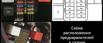
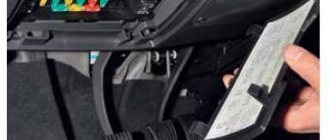
The fuse box is located on the right side of the instrument panel.
To access the fuses, you need to slide the cover labeled “Volga” to the right.
diagram of the location of fuses in the block.
LEFT BLOCK
High beam right headlight
High beam headlights, high beam headlight warning light
Low beam right headlight
Low beam left headlight, electric corrector
Electric fan relay, heated seat relay, parking brake warning relay, windshield washer jets
Cigarette lighter, horn relay, horns
Rear fog light
Engine compartment lamp, glove compartment lamp, interior lamp
RIGHT BLOCK
Fog lights, rear fog light
Heater, rear window defroster relay, rear window defroster
Reversing light, instruments, speedometer sensor
Brake lights, portable lamp socket
Left side lights, fog light relay, side light indicator
Heated rear window
Electric fuel pump (ZMZ-4062)
Engine control system unit (ZMZ-4062) or EPHH unit (ZMZ-402)
Turn signals, repeaters, breaker and turn signal indicators
Right side lights, trunk lights, license plate lights, instruments, cigarette lighter
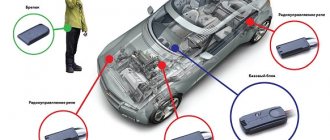
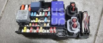
An additional gas fuse box 3110 is installed in the engine compartment on the left mudguard.
30A fuse protects the cooling fan circuit
A 60A fuse protects the entire circuit except the starter circuit.
Gas relay block 3110.
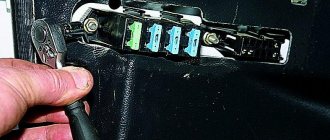
The rear window heating relay, headlight relay, windshield wiper, heater motor, sound signals, fog lights, direction indicators are installed in a common block under the instrument panel on the left side. To access the crele, use a screwdriver to unscrew the three screws and remove the cover.
The relay does not have a fixed location, so we focus on the color and number of wires, comparing them with the diagram below.
Electrical diagram of gas 3110 with ZMZ-402 engine.
To enlarge the image, click on it (the diagrams are high-quality, you will have to wait a little).
B1 — oil pressure indicator sensor; B2 - emergency oil pressure indicator sensor; B7 — coolant temperature indicator sensor; B8 - engine overheat sensor; B12 - fuel level indicator sensor; B20 — cooling system fan thermal switch; B46 — speedometer sensor; B67 — brake fluid level sensor; B68 - sensor-distributor; B93 - carburetor air damper warning lamp sensor; D4—EPHH control unit; E1, E2 - left and right headlights; E3, E4 - left and right fog lights; E7, E8 - left and right direction indicators; E9, E10 - left and right side turn signals; E16 — interior lamp; E27, E28 - left and right rear lights; E30, E72 — license plate illumination; E35 - engine compartment lighting; E59 - cigarette lighter; E61 - trunk lighting; E71 - glove compartment lighting; E80 - additional brake light; E81, E82 - rear light in the trunk lid; F1-F4 - spark plugs; F41 - left fuse box; F42 - right fuse box; F43 - fuse box in the engine compartment; G1 - generator; G2 - battery; H1, H2 - sound signals; H7 - emergency oil pressure indicator; H8 - overheat indicator; H16 - right turn indicator; H17 - left turn indicator; H19 - fuel reserve indicator; H20 - high beam headlight indicator; H30 - indicator of the engaged parking brake; H54 - generator malfunction indicator; H56 - brake fluid level drop indicator; Н62, Н63 — front side lamps; H64, H65 - headlight lamps; Н66-Н69 — backlight lamps; H70, H71 - rear fog lights; H72, H73 - reversing lights; H74, H75 - brake lights; Н76, Н77 — rear side lamps; Н78, Н79 — rear direction indicators; H80 — side light indicator; H81 - backup control lamp; H92 - carburetor air damper warning lamp; H97 - seat heating indicator; K1 - starter relay; short circuit - windshield wiper relay; K7 - sound signal relay; K12 — turn signal relay; K13 - parking brake indicator relay; K20 - fog lamp relay; K36 — cooling system fan motor relay; K40 - headlight relay; K42 — rear window heating relay; K54 - seat heating relay; M1 - starter; M2 — heater fan electric motor; M3 — electric motor of the engine cooling fan; M4 - windshield wiper; M5 - windshield washer pump; M19 - antenna drive; P1 — speedometer; P2 - instrument cluster; RZ - tachometer; P5 - voltmeter; P6 - coolant temperature indicator; P7 - oil pressure indicator; P8 - fuel level indicator; R1- R4 - noise suppression resistors; R12 — heater fan resistor; R14 — rear window heating element; R17, R18 — seat heaters; R25, R26 — heaters for glass washer jets; S1 - ignition switch; S5 - alarm switch; S6 — heater fan switch; S9 — direction indicator switch; S12 — windshield wiper switch; S18 — fog lamp switch; S19 — fog lamp switch; S29 — reverse light switch; S30 - brake light switch; S36 - horn switch; S39 - central light switch; S52 - parking brake switch; S54 - switch for checking the serviceability of indicator lamps; S61 — rear window heating switch; S63 - antenna switch; S70, S71 - door switches; S72 — EPHH system switch; S77 - glove compartment lighting switch; S91, S92 - seat heating switches; S109 — washer jet heating switch; T1 - ignition coil; V1 - voltage regulator; V2 — ignition system switch; V3 — electromagnetic valve EPHH; U2 - radio; X3 - portable lamp socket.
Electrical diagram of gas 3110 with ZMZ-4062 engine.
B1 — oil pressure indicator sensor; B2 - emergency oil pressure indicator sensor; B7 — coolant temperature indicator sensor; B8 - engine overheat sensor; B12 - fuel level indicator sensor; B20 — thermal switch of the electric cooling fan; B46 — speedometer sensor; B67 — brake fluid level sensor; E1, E2 - left and right headlights; E3, E4 - left and right fog lights; E7, E8 - left and right direction indicators; E9, E10 - left and right side turn signals; E16 — interior lamp; E27, E28 - left and right rear lights; E30, E72 — license plate illumination; E35 - engine compartment lighting; E59 - cigarette lighter; E61 - trunk lighting; E71 - glove compartment lighting; E80 - additional brake light; E81, E82 - rear light in the trunk lid; G1 - generator; G2 - battery; H1, H2 - sound signals; H7 - emergency oil pressure indicator; H8 - overheat indicator; H16 - right turn indicator; H17 - left turn indicator; H19 - fuel reserve indicator; H20 - high beam headlight indicator; H30 - indicator of the engaged parking brake; H54 - generator malfunction indicator; H56 - brake fluid level drop indicator; Н62, Н63 — front side lamps; H64, H65 - headlight lamps; Н66-Н69 — backlight lamps; H70, H71 - rear fog lights; H72, H73 - reversing lights; H74, H75 - brake lights; Н76, Н77 — rear side lamps; Н78, Н79 — rear direction indicators; H80 — side light indicator; H91 - injection system malfunction indicator; H97 - seat heating indicator; K1 - starter relay; K3 - windshield wiper relay; K6 - air conditioner mode relay; K7 - sound signal relay; K12 — turn signal relay; K13 - parking brake indicator relay; K20 - fog lamp relay; K36 - cooling fan motor relay; K40 - headlight relay; K42 — rear window heating relay; K54 - seat heating relay; K56 - air conditioner relay; K57 - compressor clutch relay; M1 - starter; M2 — heater fan electric motor; M3 — electric motor of the engine cooling fan; M4 - windshield wiper; M5 - windshield washer pump; M6 - fuel pump; M19 - antenna drive; M33, M40 - air conditioning fans; M38, M39 - electric headlight corrector; P1 — speedometer; P2 - instrument cluster; P3 - tachometer; P5 - voltmeter; P6 - coolant temperature indicator; P7 - oil pressure indicator; P8 - fuel level indicator; R12 — heater fan resistor; R14 — rear window heating element; R17, R18 — seat heaters; R25, R26 — heaters for glass washer jets; R28 - air conditioner fan resistor; S1 - ignition switch; S5 - alarm switch; S6 — heater fan switch; S9 — direction indicator switch; S12 — windshield wiper switch; S18 — fog lamp switch; S19 — fog lamp switch; S29 — reverse light switch; S30 - brake light switch; S36 - horn switch; S39 - central light switch; S52 - parking brake switch; S54 - switch for checking the serviceability of indicator lamps; S61 — rear window heating switch; S63 - antenna switch; S70, S71 - door switches; S77 - glove compartment lighting switch; S91, S92 - seat heating switches; S109 — washer jet heating switch; S116 — remote control for electric headlight adjustment; S117 - air conditioner switch; S118 — air conditioner mode switch; U2 - radio; X3 - portable lamp socket; Y27 - electromagnetic clutch of the air conditioning compressor.
Removing and disassembling the windshield wiper, replacing its relay
Lift up the protective cap of the lever.
Use a 10mm wrench to unscrew the nut...
...and using sliding pliers we pull the lever from the slots.
Similarly, remove the second lever.
Using a thin screwdriver, we remove the six plugs for the bushings securing the front panel trim.
Using a slotted screwdriver, unscrew the six self-tapping screws securing the cladding...
...and take them out along with the plastic bushings.
Using a 24mm wrench, unscrew the nut securing the outer panel cladding.
We remove the panel.
Disconnect the fluid supply hose from the tee.
Using a 24mm wrench, unscrew the nuts securing the two purifier bushings...
...and remove the sealing gaskets.
Disconnect the wiper block in the engine compartment.
Using a 10mm wrench, unscrew the two bolts securing the windshield wiper bracket to the body.
Remove the windshield wiper. In order to remove the left rod bushing from the hole in the body panel, close the hood halfway.
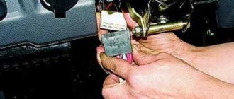
Using a screwdriver, unscrew the two screws and disconnect the wire tips from the bimetallic fuse.
If the wiper blades did not extend beyond the boundaries of the windshield during operation, before disassembling...
...we mark the relative position of the gearmotor and the crank on its shaft.
Use a 13mm wrench to unscrew the nut...
...and remove the crank from the shaft splines.
Unscrew the three screws securing the bracket to the gearmotor.
Remove the rod mechanism with the bracket.
We assemble and install the purifier in the reverse order. At the same time, we place the crank on the gearbox shaft according to the mark. After installing a new wiper or replacing the gearbox, it is possible that the wiper brushes, moving, will extend beyond the glass. This problem cannot be eliminated by rearranging the brushes on the splines. It is necessary to rearrange the crank on the gearbox shaft to ensure proper operation of the wiper. To replace the wiper relay...
...in the engine compartment (above the expansion tank) remove the connecting block from the relay terminals.
Using a 10mm wrench, unscrew the bolt and remove the relay.
www.autofizik.ru
Car diagram - Volga 3110
Here are the electrical circuit diagrams for the GAZ 3110 1996-2004. External distinguishing features were new fenders, roof shape, hood, aprons, and radiator grille. Only the doors remained the same. At first, GAZ 3110 cars were equipped with narrow black bumpers, and since 2000 they were replaced by new modern bumpers, which began to be painted in body color. They gave the car a more impressive look due to the additional volume. A distinctive feature was the trunk lid, which opened from the bumper itself in order to facilitate loading things into the luggage compartment. In 2001, cars began to be painted and primed using a new system, which increased the service life of the body. There was also a special version of the GAZ 3110 for taxi services, which had a special coloring, preparation for a taximeter and interior trim made of easy-to-clean materials.
Diagram of the ignition system for Volga 3110
1 – M 1.5.4 engine control unit 9 – diagnostic connector 2 – phase sensor 10 – engine control system relay 3 – speed and synchronization sensor 11 – fuel pump relay 4 – air throttle position sensor 12 – idle speed regulator 5 – sensor detonation 13 – injector 6 – mass air flow sensor 14 – ignition coil 7 – coolant temperature sensor 15 – spark plug 8 – air temperature sensor in the intake pipe
Wiring diagram of GAZ-3110 equipment with ZMZ-4062 engine
1 – turn signal 46 – instrument cluster 2 – headlight 47 – speedometer 3 – fog lamp 48 – tachometer 4 – sound signal 49 – voltmeter 5 – side repeater 50 – battery discharge warning lamp 6 – ignition switch 51 – instrument illumination lamp 7 – fuse box in the engine compartment 52 – right turn indicator lamp 8 – generator 53 – left turn indicator lamp 9 – power socket 54 – parking brake indicator lamp 10 – engine compartment lamp 55 – seat heating indicator lamp 11 – battery 56 – side light indicator lamp 12 – electric fan activation sensor 57 – high beam headlight control lamp 13 – electric fan 58 – brake fluid level drop warning lamp 14 – horn relay 59 – KMSUD warning lamp 15 – left fuse block 60 – coolant temperature indicator 16 – horn switch 61 – fuel level indicator 17 – brake fluid level drop sensor 62 – fuel reserve indicator lamp 18 – headlight switch relay 63 – coolant overheat indicator lamp 19 – starter 64 – oil pressure indicator 20 – starter relay 65 – emergency oil pressure drop indicator lamp 21 – central light switch 66 – backup warning light 22 – brake light switch 67 – front door light switch 23 – reverse light switch 68 – interior light switch 24 – windshield wiper switch 69 – rear door light switch 25 – windshield washer electric pump 70 – warning light breaker parking brake 26 – windshield wiper motor 71 – parking brake warning lamp switch 27 – wiper relay 72 – luggage compartment light 28 – electric fan relay 73 – rear window heating element 29 – radio 74 – windshield washer jet heating switch 30 – antenna motor 75 – heating relay seats 31 – antenna switch 76 – seat heating switch 32 – glove compartment lighting lamp 77 – seat heating elements 33 – glove compartment lighting lamp switch 78 – coolant overheating warning lamp sensor 34 – fog lamp relay 79 – coolant temperature indicator sensor 35 – fog light switch 80 – warning lamp sensor for emergency oil pressure drop 36 – rear fog lamp switch 81 – oil pressure indicator sensor 37 – rear window heating relay 82 – fuel pump 38 – rear window heating switch 83 – fuel level indicator sensor 39 – switch heater fan 84 – switch for diagnostic system of indicator lamps of instrument cluster 40 – cigarette lighter 85 – windshield washer jets with electric heating 41 – right fuse block 86 – rear light on the wing 42 – speedometer sensor 87 – rear light on the trunk lid 43 – hazard warning switch 88 – additional brake signal 44 – turn signal interrupter relay 89 – license plate light 45 – turn signal switch 90 – heater fan motor
The difference between the ZMZ-402 engine and the ZMZ-4062 engine is the ignition system
Electrical diagram of Volga-3110 equipment with ZMZ-402 engine
1 – turn signal 48 – turn signal interrupter relay 2 – headlight 49 – hazard warning switch 3 – fog lamp 50 – speedometer sensor 4 – horn 51 – instrument cluster 5 – side repeater 52 – speedometer 6 – spark plug 53 – tachometer 7 – ignition distributor 54 – voltmeter 8 – transistor switch 55 – battery low indicator lamp 9 – ignition switch 56 – instrument backlight lamp 10 – windshield wiper motor 57 – right turn indicator lamp 11 – wiper relay 58 – left turn indicator lamp 12 – pump electric motor windshield washer 59 – parking brake indicator lamp 13 – windshield wiper switch 60 – seat heating indicator lamp 14 – EPХХ system switch 61 – side light indicator lamp 15 – EPХХ solenoid valve 62 – high beam headlight indicator lamp 16 – ЭПХХ control unit 63 – fall indicator lamp brake fluid level 17 – ignition coil 64 – coolant temperature indicator 18 – fuse box in the engine compartment 65 – fuel level indicator 19 – starter 66 – fuel reserve warning light 20 – starter relay 67 – coolant overheating warning light 21 – generator 68 – oil pressure indicator 22 – voltage regulator 69 – warning lamp for emergency drop in oil pressure 23 – brake fluid level drop sensor 70 – backup warning lamp 24 – headlight switch relay 71 – front door lamp switch 25 – central light switch 72 – interior lamp 26 – brake light switch 73 – rear door lamp switch 27 – reverse light switch 74 – oil pressure indicator sensor 28 – horn switch 75 – emergency oil pressure drop warning lamp sensor 29 – battery 76 – coolant overheat warning lamp sensor 30 – plug socket 77 – coolant temperature gauge sensor 31 – engine compartment lamp 78 – seat heating elements 32 – left fuse block 79 – seat heating switch 33 – horn relay 80 – seat heating relay 34 – radio receiver 81 – windshield washer jet heating switch 35 – lamp switch glove compartment lighting 82 – parking brake warning lamp breaker 36 – glove compartment lighting lamp 83 – parking brake warning lamp switch 37 – antenna motor 84 – luggage compartment light 38 – antenna switch 85 – rear window heating element 39 – fog lamp relay 86 – heater fan motor 40 – fog light switch 87 – rear fender light 41 – rear fog light switch 88 – rear luggage compartment lid light 42 – rear window heating relay 89 – license plate light 43 – rear window heating switch 90 – additional brake signal 44 – heater fan switch 91 – windshield washer jets with electric heating 45 – cigarette lighter 92 – instrument cluster warning lamp diagnostic system switch 46 – right fuse block 93 – fuel level indicator sensor 47 – turn signal switch 94 – carburetor choke warning lamp sensor
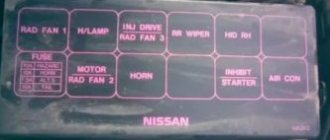
Fundamental differences in the design of the fuse box depending on the Gazelle model
This is what the new fuse box looks like
The design differences of the modification of the Gazelle class, based on various electrical equipment protection systems, can be divided into the following main groups and their features can be highlighted. Watch the video on how to install a new fuse box.
Cars with carburetor-type gasoline engines
- Cars produced before 2003:
- equipped with old-style electrical fuse modules with cylindrical type fuses with a nominal value of 8 and 16A;
- control relays are installed separately from the mounting block;
- the engine compartment block (BPR-2) has power fuses of 40A for the light circuit and 60A for the general plus.
- Models 2003-2010:
- new-style units with plastic fuses with protection thresholds of 5, 10, 15, 20 and 25A were installed, depending on the equipment;
- control relays are also located independently of the unit;
- the power protection module can be different: BPR-2 with protection of 90A for the light and generator circuits and 60A for the general plus.
- BPR-4 for cars with a pre-installed anti-lock braking system and additional 25 and 40 A electrical fuses.
Cars with gasoline injection engines
- The main fuses of plastic type 25, 10, 15, 20 and 5A for various circuits are combined into a single mounting module located in the cab.
- The main control relays are included in the unit.
This is what control relays look like for a Gazelle car
Installation process of protective relays
Diesel vehicles
- A main safety module is installed, similar to fuel-injected cars, with additional 5A electrical fuses for the engine management system.
- Modified engine compartment, including protected circuits:
- air heating system with 125A protection;
Schematic design of the air heating system in a gazelle
Diagram with car fuse sizes
The variety of factory configurations of Gazelle cars, both in terms of the pre-installed engine and additional equipment, and the multiplicity of their combinations leads, in turn, to differences in the electrical protection system and the design of the mounting block.
Thus, the Gazelle fuse box is a mandatory element of the protective mechanism of the vehicle’s electrical equipment and is implemented taking into account the design features of a specific modification of the vehicle.
The two-level construction of the safety circuit provides reliable protection of on-board devices, both from a short circuit in the machine network and from voltage surges, thereby ensuring their trouble-free operation.
FakeHeader
Comments 33
Good afternoon, one of these days I will also make one for myself, I’m studying the information and I don’t understand one thing, the jumpers are not all installed the same way, each one is somehow different, so I’m sitting and thinking, how should I install it, maybe there is some difference?
Good afternoon. I compared it with the original diagram and did not notice any contradictions. It really was such a long time ago.
Ok, I’ll make it according to your scheme!
But I still recommend looking at the diagram and the connections in the car and in general at the colors of all the wires, you never know, someone has messed with the wiring before. For reinsurance in general, so as not to accidentally do something bad.
Well, it seems like there is no additional equipment, not even heating the glass, look for a diagram on the Internet? To be honest, I’m also worried about this, as if there were no extra wires and twists where they weren’t needed.
In my car in the glove compartment there is a book from the previous owner, I look there if anything happens. Of course there is on the Internet. By the way, where is another option for installing jumpers? In theory, everyone should have the same.
Here I studied it during the drive, maybe of course I took a look, but it seems to me they did it differently, if I find it I’ll send a screenshot, there’s no book, the car is old, but cheerful)))))
Well, good luck to you, with these minor modifications she will also be less capricious)
Thank you, it’s already enough, then the headlights will go out, then the washer, maybe there will be less drawdowns, I read that drawdowns can also be due to the fault of the fuses, tell me what ratings you set, there the fuses cost 8 and 16 amps, like, and what euros to put in when buying a block, large denominations cost
You can look at the photo, you can see it, and it’s also labeled on the diagram. That's how it works for me.
Great article, I’ll be doing something similar, thanks!
Today my fuse block also died for a long time after I turned on the high beams in the village part of the city. The high beam turned off (and, as it turned out later, upon arriving at the garage to unload free spare parts, the interior lighting also turned off), and I almost went crazy - I was afraid that I wouldn’t make it home: it was dark, even though it was eight in the evening. When I try to “blink” the high beams, the relay does not click. But it’s good that the low beam didn’t fail. After I arrived home, I removed the protective caps from the fuse block and burned myself on some of the mounting contacts - they got hot enough that the fuse mountings themselves began to heat up, although the fuses themselves are visually intact (you can’t see much in the dark with a flashlight). Now I’ll wait for my payday and get ready to spend the weekend with a soldering iron in my hand in the garage.
p.s.: did you have to bend any of the seats to install the Volgov block on the original mounts of the Zhiguli block?
Wipers do not work on the Volga
On the majority of Volga cars still in use today, the axles of the windshield wiper blades are located symmetrically relative to the car body. As a result, the left blade does not reach the edge of the windshield by 10-15 centimeters, which naturally makes it difficult for the driver to see when making left turns in bad weather. Only on the GAZ-3105 and GAZ-3111 this design fault was eliminated, but these were executive class cars, and if we count the total number of these cars produced, then there are less than five hundred of them.
Another problem for Volga car drivers is created by a thermal bimetallic fuse, which cuts off the power to the wiper motor at the slightest increase in load on the trapezoid crank. If you short-circuit this fuse and turn on the wipers, but they start working, then you will have to remove the trapezoid and look for the reason for its jamming. It is possible that the trapezoid joints simply lack lubrication and need to be cleaned and lubricated.
True, there are cases when the thermal fuse plate, as a result of overheating, becomes deformed, which is why, after it cools down, the contacts do not automatically close, which leads to a break in the power supply circuit of the wiper motor, and they stop working. This fault is very similar to a blown fuse protecting this electrical circuit.
If you own a GAZ-3110 car, then look for a ten-amp fuse No. 13 of the windshield wiper in the left fuse block. Its color is red. To gain access to the fuse box, you must remove the cover that covers it. To do this, slide the cover with the inscription “Volga” to the right and you can stick your finger into the opened hole, with which you pull out this cover by pulling it towards you.
When it turns out that the fuse is intact, then using a tester you will have to check the circuit, from under the steering switch to the wiper motor. If this circuit is in order, then we apply voltage directly to the terminals of the wiper motor, and if it works, then you will have to remove it under the steering switch and look for a fault in it.
When the wipers refuse to work in intermittent mode, the cause of the malfunction may be the failure of the relay, through which, only in this mode, power is supplied to the terminals of the wiper motor. On the Volga GAZ-3110 you can find it in the relay block, which is located behind the plastic cover in the area of the driver’s left foot. It is located in the first row (if the countdown is from the engine), second from the bottom.
Share this article with your friends:
helping-auto.ru
Recommendations
Comments 9
406 motor. The generator heats up, the positive contact on it and the wire to the fuse. new generator at 100a. The wire is visually normal. I can't understand the reason. maybe someone had this happen
W - “phase output”, for example for connecting a tachometer, is currently not used by anyone, but for the correct connection of D+, see Fig. 9 - amastercar.ru/articles/el...equipment_of_car_11.shtml HL - control light with a picture of the battery in the tidy.
“B+ is charging, D+ is excitation, W is the output of one of the phase windings of the stator (it has alternating voltage). It can be used, for example, to connect a tachometer or hour meter on some special equipment. On AvtoVAZ products this terminal is not particularly relevant.”
information from the internet)
D+ - for tidy, voltage. W - to the tachometer.
So, D+ for tidy or excitement?
Electrical equipment GAZ 3110
As in any car, the GAZ 3110 electrical circuit contains automotive wiring with connectors, various relays and sensors, fuses, instruments, as well as energy sources and consumers. Energy sources are a generator and a battery; consumers include:
Starter design diagram for Gas 3110
The Volga 3110 has an electronic speedometer. It should be noted that on the previous GAZ 31029 model the speedometer was equipped with a mechanical drive (cable). Also, unlike the 31029, the 3110 model now has a tachometer.
But the new device cannot immediately work on a GAZ car without problems, and therefore various problems arose with the speedometer and tachometer.
The tachometer in the first models had the following flaw - the instrument needle trembled, indicating the number of revolutions. Later, the manufacturer brought the device to perfection, and the owners of the first cars had to fix the defects with their own hands - solder an additional resistor into the tachometer circuit.
Tachometer from Volga 3110
Gazelle fuse box design
The main functional purpose of the Gazelle fuse box, as in other cars, is to protect the car’s electrical appliances from short circuits or increased voltage in the on-board network. Its task is to promptly open the circuit during overloads, and thereby avoid failure of the electrical appliance it protects.
This is what a gazelle fuse box looks like
However, despite all the differences, the implemented basic principles of electrical equipment protection are preserved in all modifications of the Gazelle.
Electrical faults
Volgas have never been particularly reliable, and the electrical equipment on the car is far from ideal in quality. What are the main electrical faults found on the GAZ 3110:
Electrical diagram of the Volga 3110 windshield wiper
- On the 406th engine:
- the generator often “flies”, it is not always enough for 50 thousand km;
- the engine control unit is not very reliable;
- Domestic air flow sensors often fail;
- The phase sensors are not of high quality - because of it, fuel consumption increases.
- On the 402nd engine:
- Switches overheat and fail;
- The ignition coil is not of the best quality; it is not for nothing that car owners carried a switch and a coil with them in the trunk of their car.
Electrical wiring also often fails the owners of the 3110 - unreliable contacts can be in any connection. Fires in the engine compartment also happen due to wiring, although most often the car owners themselves are to blame for this. If there is dirt and oil under the hood, and gasoline is leaking from the fuel hoses, no car will withstand such careless treatment.
Blocks under the hood
Under the hood there are some additional elements of fuses and relays Gas 31105 Chrysler.
Fuse box
It is mounted on the left mudguard and consists of fusible links, closed with a protective cover.
Scheme
Purpose
- 60 A protects the anti-lock brake system (ABS) circuit;
- 60 A for almost all power supply circuits of vehicle consumers, except for the starter circuit and those protected by the remaining fuses of the unit;
- 40 A power supply circuit for vehicle lighting and light signaling;
- 90 A circuit of the battery, generator, electric headlight washer (if equipped) and the power circuit of the electric radiator fan of the engine cooling system.
On vehicles not equipped with ABS brakes and manufactured before July 2006, fuse No. 1 was not used.
Since July 2006, through this fuse, terminal “A29” of the engine control unit has been connected to the generator, through which the function of controlling the excitation current of the generator is carried out (voltage adjustment in the vehicle’s on-board network).