How to change Jetta fuses
First you need to remove the fuse box cover. Under the hood it is secured with a latch at the rear, and in the cabin it is simply removed using the lower edge. Next, you need to take pliers and pull out the required fuse, which a fuse diagram will help you find. Such a diagram is often drawn on the block cover, but unfortunately this is not the case with the Jetta; it has neither a layout diagram nor fuse ratings. Therefore, it should be found in the user manual or repair manual. If you do not have such a brochure, then the Jetta 6 fuse diagram is available in our photo report.
It is worth holding the fuse up to the light to make sure that its thread has blown. Then eliminate the reason why it blew and install a new fuse of the same rating as its predecessor.
Removal and replacement process
The need to replace a burnt-out part arises in several cases:
- first of all, this is poor contact on the power supply sockets (to increase the service life of the elements, the sockets must be periodically cleaned);
- in addition, this may be a mismatch between the rating of the installed part and the load current of the circuit (to avoid this, it is necessary to select elements with the same amperage);
- short circuit in the circuit protected by the part;
- failure of the main electrical equipment (generator, starter, etc.).
Below we will consider the procedure for removing and replacing fuses in blocks. Regardless of which component you need to replace, the steps will be approximately the same.
- First, you should open the hood and disconnect the battery. To do this, remove the negative terminal from it.
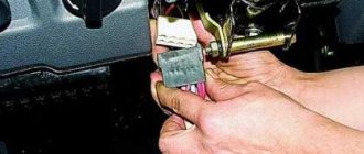
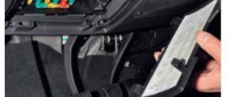
- If you need to replace the fuse in the mounting block installed directly on the battery, then press the plastic cover and remove it. If you need to replace a device in the power supply located under the steering wheel, then simply press the decorative cover located under the steering wheel. If you need to replace the fuse in the block located on the end side of the dashboard, open the driver's door and use a screwdriver to pry off the power supply cover.
- By doing this, you will be able to see the fuses located in one of your PSUs. If you know for sure which component needs to be replaced, then dismantle it using special pliers (for fuses) or by hand (if you need to replace a relay). If you do not know exactly which element has failed, then you will have to conduct a visual inspection of the power supply. On the back of the power supply cover there is a diagram of the arrangement of elements, according to which you can identify the faulty component. If you have problems identifying a burnt-out part, then inspect each element. If the device breaks down, its fusible thread will be torn, and the body of the part itself will be burnt out. Replace the failed fuse with a new one of the same rating.
- After completing the part change, close the cover of the mounting block and do not forget to connect the negative terminal of the battery.
Pry up the protective cover of the mounting block located under the steering wheel of the car.
Open the lid. Do not forget to disconnect the battery before replacing power supply elements.
Using tweezers, remove the burnt part and replace it with a new one. Reconnect the battery.
Also note: when changing components, you should never use improvised means. For example, some Russian and Ukrainian motorists install homemade parts instead of traditional fuses. As a rule, they are simply a bent paper clip or a piece of wire.
Our site strongly does not recommend resorting to such “solutions”. In addition to the fact that a home-made fuse can cause equipment failure, it can also cause a short circuit in the circuit and, as a result, a fire.
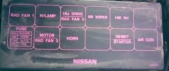
Fuse box: diagram and location
Relay and fuse box on models produced before 1989
There are two main models of Volkswagen Jetta electrical equipment, each of which has its own fuse layout. For models produced before 1989, the block and its diagram look as shown in the figure. Moreover, the value of the maximum permissible current that the contact element can withstand is marked on the body of the fuse itself. Well, its color corresponds to a certain value of this current.
| Current value, A | Element coloring |
| 30 | Green |
| 20 | Yellow |
| 15 | Blue |
| 10 | Red |
The fuse box diagram for Volkswagen Jetta cars manufactured after 1989 was slightly changed and began to look like this. It is worth mentioning that also in this block, under the fuses, spare contact elements began to be located. In addition, there is a special tweezers for carefully removing fuses from the contact connectors.
Relay and fuse box on models produced since 1989
It must be remembered that each element is responsible for protecting against failure of one circuit. The latest Volkswagen Jetta models have an algorithm that determines the sequence and location of the fuses. Next, we will look at a list that makes it easy to identify which contact element is responsible for which electrical circuit in a Volkswagen Jetta.
| Element serial number | Electrical circuits | Load, A |
| 1 | Left low fire | 10 |
| 2 | Right low fire | 10 |
| 3 | Driver's panel illumination License plate illumination | 10 |
| 4 | Glove box lamp | 15 |
| 5 | Windshield washer and cleaner | 15 |
| 6 | heating fan | 20 |
| 7 | Taillight, right, parking light signal | 10 |
| 8 | Heated rear window | 20 |
| 9 | "Fogs" | 15 |
| 10 | Left high beam light | 10 |
| 11 | Right high beam light | 10 |
| 12 | Signal horn | 10 |
| 13 | Vehicle warning lights when driving in reverse Heated washer fluid reservoir | 10 |
| 14 | In diesel model, fuel shut-off valve | 10 |
| 15 | Driver's instrument panel | 15 |
| 16 | hazard warning lamps | 10 |
| 17 | Free (spare) contact | – |
| 18 | interior fan air conditioner | 30 |
| 19 | Stop signal lamp | 10 |
| 20 | Lighting source inside the car | 15 |
| 21 | Cigarette lighter in the cabin and FM radio | 10 |
Remember, if any Volkswagen Jetta contact element is faulty, do not replace it with wire or more suitable means. The fact is that the imperfection of such improvised means can lead to serious damage to Volkswagen equipment. Well, for the owner this can result in expensive and time-consuming repairs. And not only the fuse box, but also the devices connected to the electrical circuit.
Thus, when replacing these elements, you must follow the diagram indicating their location. It is located on the back of the unit cover. When troubleshooting, use only original Volkswagen Jetta parts. As a result, you will receive a prompt and competent solution to the issue of repair and replacement of faulty fuses.
The 6th generation Volkswagen Jetta was produced from 2010 to 2016. Protection of the on-board electrical network and its components consists of relays and fuses. For ease of maintenance, they are assembled into several separate modules.
Volkswagen Polo Sedan 1.6 fuses
Mounting block A of fuses in the engine compartment
| Mounting block A fuses in the engine compartment | |
| Fuse designation (rated current, A) | Protected elements |
| AS1 (150/175) | Generator |
| AS2 | Reserve |
| AS3 (110) | Ignition switch, light switch, steering column switches, ignition switch contact relief relay, fuel pump relay, fuel supply relay when opening the driver's door, low beam headlight relay, fuse circuit SB4, SB20 SB56, parking light relay, power supply relay terminal 30 |
| AS4 (50) | Power steering control unit |
| AS5 (40) | ABS control unit |
| AS6 (40) | Cooling fan control unit |
| AS7 | Reserve |
Mounting block From the fuses in the engine compartment (cover removed)
| Mounting block C fuses in the engine compartment | |
| Fuse designation (rated current, A) | Protected elements |
| CS1 (25) | ABS control unit |
| CS2 (30) | Cooling fan motor control unit, cooling fan motor |
| CS3 (5) | Cooling fan motor control unit |
| CS4 (10) | ABS control unit |
| CS5 (5) | Electrical package control unit |
| CS6 | Reserve |
Mounting block B of fuses in the car interior
| Fuses for mounting block B in the car interior | |
| Fuse designation (rated current, A) | Protected elements |
| BS1 | Reserve |
| BS2 (10) | Steering column switches, windshield washer pump |
| BS3 (5) | Fuel pump relay, engine control module |
| BS4 (2) | Steering column switches |
| BS5 | Reserve |
| BS6 (5) | Instrument cluster control unit |
| BS7 (5) | Headlight beam direction control, license plate lights |
| BS8(10) | Injectors or reserve |
| BS9 (5/7.5) | ABS control unit, ASR/ESP switch, steering column switches |
| BS10 (5) | Vehicle speed sensor, automatic transmission selector, power accessories control unit, ignition switch |
| BS11 (5) | Headlight beam direction regulator, gear motors in headlights |
| BS12 (5) | Regulator for electric drives of exterior mirrors |
| BS13 (15) | Automatic transmission control unit, automatic transmission multifunction switch, automatic transmission selector |
| BS14 (5) | Airbag control unit |
| BS15 (5) | Windshield washer jet heating elements |
| BS16 (5) | Parking sensor control unit |
| BS17 (15/10) | Heating elements for oxygen concentration sensors, adsorber purge valve |
| BS18 (5) | Instrument cluster control unit, left rear fog lamp |
| BS19 (5) | Parking light relay, audio head unit, power accessories control unit, ignition switch |
| BS20 (5) | Instrument cluster control unit, steering column switches |
| BS21 (10) | Electrical package control unit, directional lamps, interior lamp with switch-off delay, trunk lamp |
| BS22 (5) | Diagnostic connector, air conditioning control unit, climate control unit, key lock solenoid in ignition switch |
| BS23 (7.5) | Electrical package control unit, engine control unit, automatic transmission control unit, automatic transmission switch (manual mode) |
| BS24 (5) | Electrical package control unit, heated exterior mirrors |
| BS25 (5) | Refrigerant pressure sensor, air conditioning compressor relay, cooling fan control unit, air conditioning control unit, diagnostic connector, heating and ventilation control unit |
| BS26 (7.5) | Power steering control unit |
| BS27 (5) | Reversing light switch in the right rear lamp |
| BS28 | Reserve |
| BS29 | Reserve |
| BS30 | Reserve |
| BS31 | Reserve |
| BS32 (10) | Fuel pump or reserve |
| BS33 (5) | Clutch pedal position sensor, brake light switch |
| BS34 (7.5) | Right block headlight (high beam) |
| BS35 (10) | Engine control unit |
| BS36 (10/15) | Fuel pump or injectors |
| BS37 (25) | Driver seat heating control, front passenger seat heating control, front seat heating control unit |
| BS38 (7.5) | Left headlight unit (high beam), instrument cluster control unit |
| BS39 (10) | Right block headlight (low beam) |
| BS40 (30) | Heater fan switch, heater fan control unit |
| BS41 | Reserve |
| BS42 (15) | Cigarette lighter |
| BS43 (15) | Electrical package control unit, turn signal lamps, brake signal lamps |
| BS44 (15) | Ultrasonic burglar alarm sensor, burglar alarm siren |
| BS45 (15) | Navigation system control unit, audio headunit, multimedia system control unit |
| BS46 (20) | Electrical package control unit (high-pitched sound signal) |
| BS47 (20) | Electrical package control unit (wiper motor) |
| BS48 (25) | Electrical package control unit (central locking, electric fuel filler flap) |
| BS49 (5) | Electrical package control unit (reversing light in the right rear lamp) |
| BS50 (25) | Driver door control unit |
| BS51 (25) | Front passenger door control unit |
| BS52 (30) | Left rear door control unit, right rear door control unit |
| BS53 (30) | Electrical package control unit (rear window heating element) |
| BS54 (15) | Fog lights |
| BS55 (15) | Ignition coils |
| BS56 (40) | Heated windshield relay |
| BS57 (5) | Side light bulbs in the left headlight and left rear light |
| BS58 (5) | Side light bulbs in the right headlight and right rear light |
| BS59 (10) | Left headlight (low beam) |
| BS60 | Reserve |
The information is relevant for models 2010, 2011, 2012, 2013, 2014, 2015.
carpod.ru
Fuse box locations
The 6th generation Volkswagen Jetta has two main fuse modules:
- Engine compartment unit - located in the engine compartment on the driver's side near the fender. To protect against dust and moisture, it is sealed with a sealed lid. It is secured on both sides with latches.
- Interior module - located on the driver's side at the bottom of the instrument panel under the headlight switch.
In addition to the main PCB units, the vehicle is equipped with several relay modules.
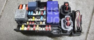
Underhood fuse module
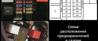
The engine compartment PCB and relay unit has six relay slots and 37 fuse slots. Not all slots are used, some are additional.
Fuse layout in the motor module.
| Protected electrical network or device | Nominal value, A | Color coding | Number on the diagram |
| Relay connector | R1 | ||
| Relay connector | R2 | ||
| Relay connector | R3 | ||
| Relay connector | R4 | ||
| Relay connector | R5 | ||
| Relay connector | R6 | ||
| Not used | 1 | ||
| Engine control unit | 10.15 | Red Blue | 2 |
| Engine Radiator Fan Relay | 5 | Brown | 3 |
| ICE controller unit | 5, 10, 15 | Brown, red, blue | 4 |
| Backup fuse | 5, 10, 15 | Brown, red, blue | 5 |
| Backup fuse | 5, 10, 15 | Brown, red, blue | 6 |
| Engine controller | 5 20 | Brown, yellow | 7 |
| Engine controller | 10 | Red | 8 |
| Glow plug controller for diesel internal combustion engines, fuel pump relay | 5.15 | Brown, blue | 9 |
| Brake light breaker, speed sensor | 5 | Brown | 10 |
| Not used | 11 | ||
| Additional engine coolant pump | 5 20 | Brown, yellow | 12 |
| Main engine coolant pump | 5 | Brown | 13 |
| Engine start controller unit | 5 | Brown | 14 |
| On-board voltage controller | 30 | Green | 15 |
| Traction control system ESP, ABS system | 30 | Green | 16 |
| Automatic transmission | 30 | Green | 17 |
| Manual transmission | 20 | Yellow | 18 |
| On-board network controller switch | 1 | 19 | |
| Front wiper relay, +12V to windshield washer | 30 | Green | 20 |
| Air pumping motor into the intake manifold | 50 | Red | 21 |
| Not used | 22 | ||
| Traction control system ESP, ABS system | 40 | Green | 23 |
| Trailer electrical connection and power controller | 50 | Red | 24 |
| Electrical network of the ignition system, gasoline internal combustion engines | 50 | Red | 25 |
| Pre-heating plugs, diesel internal combustion engines | 60 | 26 | |
| Additional engine cooling radiator fan | 60 | 27 | |
| ECU, main engine controller | 40 | Green | 28 |
| ECU, main engine controller | 40 | Green | 29 |
| Additional on-board electrical circuits | 50 | Red | 30 |
| Standard audio amplifier | 30 | Green | 31 |
| Additional heating of coolant, Webasto | 40 | Green | 32 |
| Not used | 33 | ||
| Generator protection | 200 | 34 | |
| Not used | 35 | ||
| Electric power steering column | 80 | 36 | |
| Backup fuse | 80 | 37 |