Where are the fuse and relay boxes located?
The electrical equipment system, electrical wiring and arrangement of safety blocks on the Niva 21214 and the modern Chevrolet Niva VAZ 2131 are identical. The electrical circuit of these machines has a main mounting block installed under the lower edge of the instrument panel casing in the area of the driver's left foot. An additional one is located under the main block.
A little to the left and below there is another additional block, in which inserts are installed that are responsible for the operation of the components of the fuel injection system. In addition to the fuses, there is a separate relay for controlling the wiper operation parameters and a set of relays for the engine control system.
When installing an injection engine on a car with an old wiring diagram, the designers had to install additional switching boxes.
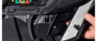
One of these blocks is located on the left side of the body near the main fuse box. Since the unit is installed in close proximity to the driver’s left foot, it is covered with a special protective plastic casing. The casing is fixed with two self-tapping screws for a Phillips screwdriver. The block itself contains a diagnostic connector and four fuses responsible for the operation of the engine and cooling system.
Block with cover removed
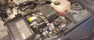
The relay responsible for turning on the engine starter can be installed separately in the engine compartment or next to the relay block. When installed under the hood, it is mounted on the compartment shield next to the brake fluid reservoir.
Fuses Niva 2121
If any equipment in a Niva 2121 car fails, first of all, it is worth checking the integrity of the safety unit. This procedure is not complicated, even an inexperienced car enthusiast can do it, so there is no need to go to a service station the first time such a situation occurs.
Replacing the block will not be cheap, but in order to do it yourself, you just need to find its location. Motorists often notice that fuses sometimes fall out of their mounts. In this case, you should replace the failed or unreliable panel with a new one in which these elements are installed in a more reliable manner. For the convenience of drivers, Niva manufacturers have placed fuses in an easily accessible place.
Designation and electrical diagram of the main and additional power supply
The designations and explanations of the fuses of the main and additional units are printed on the surfaces of the covers.
Diagram of the main and additional blocks
Description of the fuses in the upper main section of the VAZ 212214 Niva injector.
| Number on the diagram | Rated current, A | Purpose |
| PR01 | 16 | Heater fan motor, front glass fluid supply system, rear wiper motor |
| PR02 | 8 | Front wiper, direction indicators (with relay), switch block under the steering wheel, instrument cluster instruments and lamps, reverse indicator lamps |
| PR03 | 8 | High beam in the left headlight and high beam indicator lamp in the instrument cluster |
| PR04 | 8 | High beam for right headlight |
| PR05 | 8 | Low beam left |
| PR06 | 8 | Same as on the right |
| PR07 | 8 | Left side dimensions, registration plate illumination, dimensions indication on the instrument cluster |
| PR08 | 8 | Right dimensions and illumination of control devices |
| PR09 | 8 | Hazard warning relay circuit and activation button, rear defogger system |
| PR10 | 8 | Horn, interior lighting and brake lights (all three) |
Overview of the fuses of the small additional block located under the main one.
| Number on the diagram | Rated current, A | Purpose |
| PR11 and 12 | Positions are reserved | To store two 8 amp inserts |
| PR13 | 8 | Turning on the rear fog lamps |
| PR14 | 16 | Cigarette lighter |
| PR15 and 16 | Positions are reserved | For storing two inserts - 16 and 8 amps |
On Niva Urban 4x4 the fuse ratings have been slightly changed. The changed positions are listed below, the remaining chains and denominations remain the same.
| Number on the diagram | Rated current, A | Purpose |
| PR01 | 16 | Heater fan, start of heated rear window, drives for all windshield wipers and washer. Additionally (optional), this insert displays circuits for electric drives of windows and mirrors. |
| PR02 | 8 or 16 | Higher rating - heater fan and compressor (optional change - only for cars with air conditioning) |
| PR09 | 16 | Heated glass (there may be an additional option - heated mirrors) |
| PR10 | 16 | Horn, brake lights and interior lighting |
| PR11 | 8 | Alarm |
| PR12 | 8 | Daytime running light system |
| PR15 | 16 | Heater fan (not on all cars - only with air conditioning) |
Location and electrical diagram
The fuse block (hereinafter referred to as the fuse block), unlike traditional models of the domestic automobile industry, is located in the vehicle interior. In particular, it is located on the driver's side under the steering wheel. If any electrical circuit element in a car stops working (lamps, interior lights, heater, power windows), then car owners first check the power supply elements. As a rule, the problem is resolved by replacing the fuse.
What does the power supply circuit itself look like? This question may be of interest to Niva owners. Below we will look at the electrical circuit of the unit with a description of all the components responsible for the operation of certain devices in the car.
Power supply circuit for Niva
In accordance with the diagram, we will consider the meaning of the BP elements. This electrical circuit is universal for all Niva cars.
| Fuse number | Purpose |
| 1 | This block component ensures the functionality of the following elements: |
- heater fan;
- for the functioning of headlights and wiper motors; cleaning them;
- for heated rear window;
- for the work of the wipers and glass washer.
- operation of reversing lamps;
- turning on the turn signal lamps;
- turning on the windshield wiper motor;
- functioning of the carburetor damper lamps, engine fluid pressure, hand brake, brake fluid level;
- functioning of the engine temperature sensor;
- operability of the gasoline level sensor in the tank.
It should also be noted that in VAZ 21214 injector cars there is another power supply unit with injection system components. It is located separately from the main power supply on the left side under the steering wheel.
Location of additional power supply
| 2 | This circuit fuse provides: |
| 3,4 | These elements ensure the functionality of the high beam headlights. |
| 5,6 | These elements ensure the operation of low beam lamps. |
| 7 | Responsible for the operation of the instrument panel illumination lamps, license plate, and side lights. |
| 8 | It is also responsible for the operation of the side lights, interior light bulbs and the operation of the cigarette lighter. |
| 9 | Responsible for the operation of the turn signal lamps and the operation of the emergency lights. |
| 10 | The fuse of the electrical circuit is responsible for the steering horn, the power socket, and the inclusion of the brake lights. |
| 12 | Responsible for turning on the rear fog lights, as well as for the functioning of their cleaner motor. |
| 16 | Ensures the functionality of the cigarette lighter. |
| Number | Purpose |
| 1 | This element ensures uninterrupted operation of the cooling fans. |
| 2 | Ensures uninterrupted operation of the electric fuel pump. |
| 3 | Ensures the operation of the control unit |
| 4 | Ensures the functioning of the main relay of the injection system. |
Engine control system fuses
Purpose and parameters of fuses in the block (from left to right):
- 1 — ensuring the start of the electric motor of the right fan (rated 30 A);
- 2 — similar fuse-link for the left fan;
- 3 - fan relay, as well as the injection system control unit, control of injection nozzles and ignition coil (rated 15 A);
- 4 - system for reducing gas toxicity - heating of lambda probes, fuel vapor trap valve and sensor for measuring the volume of air entering the engine (rated 15 A);
- 5 - diagnostic connector for monitoring the operating parameters of the injection system.
On some VAZ 21214 with an ABS system, a fuse block with 7 inserts is installed.
Block Niva Urban
Assignment of fuses (numbering starts from the door opening).
| Number | Rated current, A | Purpose |
| PR01 | 15 | Sensors on the engine, gasoline vapor trap, starter |
| PR02 | 15 | Fans, engine operation systems (control unit, ignition, injectors) |
| PR03 | 30 | Fan starting system |
| PR04 | 15 | Gasoline pump |
| PR05 | 5 | ABS unit |
| PR06 | 40 | Likewise |
| PR07 | 25 | Likewise |
Engine Control Relay Box
The engine control relay diagram is shown in the photo.
Engine control relay
The block contains the following relays (from left to right):
- 1 — ignition activation;
- 2 - main relay, which serves to start all engine systems;
- 3 — starting the right fan on the radiator;
- 4 — start of the left fan;
- 5 — ensuring the operation of the fuel pump;
- 6 - safety element of the fuel pump power supply circuit with a rating of 15 A.
Relay block diagram above the gas pedal
The diagram of the block with the relay, which is located slightly deep in the instrument panel and is responsible for lighting the car, is shown in the photo.
The purpose of the relay in the block (from left to right) is given in the table.
| Position | Purpose |
| 01 | Rear fog lamps |
| 02 | Heated glass on the rear door |
| 03 | Low beam |
| 04 | High beam |
Fuse arrangement in a Niva 21214 car
In Niva 21214, the fuse device has a rather non-standard appearance. There is a spare one under the main fuse box, which takes over its role if the main one breaks down. Also, this car has a slightly changed role of fuses in the chain of operation, namely in their purpose. The table shows several similar examples of fuses with descriptions.
| Fuse name | Protected circuit |
| F1 | Responsible for the operation of the dimensions, license plate, lighting of the glove compartment and luggage compartment. |
| F2 | Responsible for the steering column switch. |
| F3 | Seat heating fuse. |
| F4 | Responsible for the fog lights on the left side. |
| F5 | Fuse for power windows. |
| F6 | Responsible for portable lighting. |
| F7 | Responsible for the engine cooling fan and the operation of the sound signal. |
| F8 | Responsible for the cigarette lighter. |
| F9 | Regulates the operation of the recirculation unit and the cleaning of the windshield. |
| F10 | Backup fuse can be used to charge the battery. |
| F19 | Operation of the central locking system, alternator winding, reversing lights and brake light. |
For a more detailed study, you should familiarize yourself with a more structured diagram.
This car also has a second unit, which is located above the gas pedal and includes 4 relays responsible for: interior light, proper operation of the rear lights, rear window heating switch, wipers, high and low beam.
Replacing the block
In case of burnout or mechanical damage, it is necessary to repair the unit by replacing its components or the entire assembly.
To replace the main unit, follow these steps:
- Disconnect the battery from the on-board network.
- Remove the box cover and unscrew the two 8 mm nuts securing the block. Then you need to pull the box towards you and remove it from the fastening studs.
- Write down the markings and position of the wires on the old unit.
- Disconnect the cables from the plugs of the old unit and connect them in the same sequence on the new one.
- Check fuse ratings and wire installation.
- Secure the replaced block with nuts.
- Connect power to the on-board network and check the functionality of the circuits.
The photo shows some stages of dismantling the block.
Other fuse or relay blocks on the VAZ 21214 are replaced in the same way.
Replacement
In the event of a breakdown, the fuses must be replaced in time to avoid serious problems with important components of the car in the future. The replacement process is quite simple. To do this, you simply need to remove the blown fuse and replace it with a new one.
Thus, further proper operation of the circuit for which he is responsible will be established. A very important nuance is the full compliance of the fuses (blown and new) regarding their markings and the output voltage. Otherwise, if this aspect is not taken into account, any of the elements included in the circuit that this fuse protects may burn out.
As a result, it must be said that the fuse is one of the most important parts in any car and Niva-21214 is no exception. In this regard, it is recommended to constantly monitor the condition of the mounting block and fuses. After all, if their work proceeds without any failures, then the risk of any serious electrical malfunction is reduced to almost a minimum. Thus, the key to a successful motorist is careful care of his car, and, of course, timely repair of all its components, including fuses.
Replacing fuses
If any electrical circuit in the vehicle fails, the condition of the fuse must be checked.
If it is necessary to replace parts, it should be taken into account that the VAZ 21214 fuses on the Niva injector belong to two different types:
- in the main block there are cylindrical inserts (inherited from the Zhiguli);
- and in the injection system blocks - modern, knife type.
Therefore, when you go on a trip, you need to take with you spare inserts of different types.
If, for example, a cigarette lighter fails on the road, you must:
- Turn off the ignition.
- Open the cover of the additional unit.
- Visually check the condition of the PR14 16 ampere fuse, which is responsible for the cigarette lighter circuit.
- Remove the burnt insert with your fingers and replace it with a spare one taken from the reserve socket PR15. It is prohibited to use homemade inserts, as they are not able to protect the circuit from overloads. The consequence of this may be overheating of the elements and fire.
- Check the functionality of the circuit. If the insert immediately burns out again, then the reason lies in damage to the wiring, which must be carefully checked.
The remaining fuses and relays on the VAZ 21214 are changed using a similar scheme.
Types of fuses
Over the entire period of its existence, this segment of car elements has changed more than one type. The most common ones are:
Flat fuses are considered a relatively new type. They are used in almost all new cars. They became widespread due to their increased level of reliability and relatively low cost.
The next item will be ceramic fuses, which used to be very popular, but have lost their position due to low efficiency.
The oldest of all types of fuses are glass. They are small cones made of glass. This type of fuses is practically not used today due to the low level of reliability.
These are the most common types of fuses, however, there are others, but less popular.
Location of fuse and relay blocks Niva 4x4
The main part of the fuses are located in the Niva's interior under the panel to the left of the steering column. Total 4 blocks:
1 – engine control system fuse block; 2 – windshield wiper relay; 3 – fuse blocks; 4 – engine control system relay block.
The fourth relay block is located above the gas pedal.
Relay and fuse diagram for VAZ Niva
Car owners are well aware that the VAZ 21214, 21213 (Niva) fuse box is a critical detail that requires detailed study. Knowledge of the electrical circuit allows you to avoid many problems and carry out timely diagnosis of breakdowns. Since the family has existed for many decades, it has managed to go through a number of radical changes - the transition from carburetor to injection engines, for example. This did not entail a radical change in the location and content of the mounting blocks, of which there are two in the cabin and one under the hood.
Main and additional fuse blocks
These two blocks are connected to each other. There are 10 fuses in the upper block, and 6 in the lower one. Markings from left to right:
Heater fan, rear window defroster, rear wiper and washer system, windshield washer pump
Steering column switch, windshield wipers, hazard warning lights, breaker relay (in turn signal mode), reverse light, instrument cluster (coolant temperature gauge, fuel level gauge, tachometer, warning lights: turn indicators, differential lock, parking brake, emergency condition of the working brake system, insufficient oil pressure, fuel reserve, battery charge)
Additional schemes
Diagram for switching on direction indicators and hazard warning lights
1 — direction indicator lamps in the front lights; 2 — side direction indicators; 3 — ignition switch; 4 - ignition relay; 5 — fuse block VAZ-21213; 6 — direction indicator lamps in the rear lights; 7 - control pump for direction indicators in the instrument cluster; 8 — relay-switch for direction indicators and hazard warning lights; 9 — alarm switch; 10 — direction indicator switch.
Engine control system fuses
It is located on the left side of the body, under the instrument panel, next to the diagnostic block. Consists of four fuses:
| F1 (30A) | Right electric fan relay contacts |
| F2 (30A) | Left electric fan relay contacts |
| F3 (15A) | Relay windings of the right and left electric fans, controller, injectors, ignition coil |
| F4 (15A) | Heating elements for control and diagnostic oxygen concentration sensors, phase sensor, mass air flow sensor, canister purge valve |
Fuse diagram for carburetor VAZ Niva
The only difference between Niva mounting blocks with injection and carburetor systems is related to the block. It is located under the hood of the car in a compartment specially designated for this purpose. His diagram looks like this:
Location of fuses Niva 21213
This scheme is relevant for all models of the family produced from 1997 to 1999.
Engine Control Relay Box
Below the main and additional fuse blocks there is a relay block for the engine management system, which consists of five relays and one fuse:
| №1 | Ignition relay |
| №2 | Main relay |
| №3 | Right cooling fan relay |
| №4 | Left cooling fan relay |
| №5 | Fuel pump relay (fuel) |
| №6 | Fuel pump fuse F5, 15A |
On some vehicle versions, a starter relay may be located under the additional unit next to the ignition relay.
Where are the relays located in Niva
The relay blocks in the VAZ 21213 car are located in the steering wheel area. The first fuse box is located on the left under the instrument panel.
By dismantling it, you gain access to the engine control switching unit. The relays are located there:
- Ignition Fan electric motors (2 pcs) Fuel pump activation Main switch
Below in the video you can see where the fuel pump relay is located
To replace, you will have to unscrew and lower the mounting rail on the wiring harness.
Relay block diagram above the gas pedal
| №1 | Rear fog lamp relay |
| №2 | Rear window heating relay |
| №3 | Low beam relay |
| №4 | High beam relay |
Electrical diagram of VAZ-21213
1. Front lights.2. Side direction indicators.3. Windshield washer motor.4. Headlight washer motor*.5. Switch.6. Rechargeable battery.7. Starter VAZ-21213.8. Generator.9. Headlights.10. Geared motors for headlight cleaners*.11. Sound signal.12. Spark plugs.13. Carburetor limit switch.14. Carburetor solenoid valve.15. Ignition coil.16. Windshield wiper motor gearbox.17. Carburetor solenoid valve control unit.18. Ignition distributor sensor.19. Coolant temperature indicator sensor.20. Insufficient oil pressure indicator sensor.21. Portable lamp socket**.22. Insufficient brake fluid level indicator sensor.23. Windshield wiper relay-breaker.24. Relay for turning on rear fog light lamps***.25. Relay for turning on the rear window heating element.26. Relay for turning on the headlight cleaners and washer*.27. Relay for turning on low beam headlights.28. Headlight high beam relay.30. Starter activation relay.31. Relay-breaker for hazard warning lights and direction indicators.32. Heater electric motor.33. Additional resistor for heater electric motor.34. Illumination lamps for heater control levers.35. External lighting lamp switch.36. Main fuse block.37. Additional fuse block.38. Reversing light switch.39. Brake light switch.40. Regulator for instrument lighting lamps.41. Ignition switch.42. Three-lever switch.43. Hazard switch.44. Switch for headlight cleaners and washers.45. Heater motor switch.46. Rear window heating element switch.47. Rear fog light switch.48. Lamp switches located in the door pillars.49. Interior lighting lamps.50. Cigarette lighter VAZ-21213.51. Switch for the carburetor choke indicator lamp.52. Indicator lamp for closing the carburetor air damper.53. Switch for the differential lock indicator lamp.54. Parking brake indicator lamp switch.55. Level indicator and fuel reserve sensor.56. Instrument cluster.57. Rear window washer motor.58. Tail lights.59. Block for connecting additional brake lights.60. Blocks for connecting side marker indicators.61. Pads for connecting to the rear window heating element.62. License plate lights.63. Rear window wiper motor.
The conventional numbering order in the blocks is: A – headlight and rear window windshield wipers, windshield wiper relay breaker; B – ignition distributor sensor; B – relay-interrupter for alarm and direction indicators; G – switch; D – three-lever switch; E – alarm switch; G – relay for turning on the rear fog light lamps; Z – rear lights; And – instrument clusters of VAZ-21213.
In the instrument panel wiring harness, the second ends of the white wires are brought together to one point, which is connected to the instrument lighting control. The second ends of the black wires are also brought together to a point connected to ground. The second ends of the yellow wires with a blue stripe are brought together to a point connected to terminal “A” of the main fuse block. And the second ends of the orange wires are also brought together to a point connected to terminal “B” of the main fuse block.
Mounting blocks for Lada 4×4 2018
The main and additional units are located in the cabin to the left of the steering wheel, under the instrument panel. The blocks contain fuses of the “Cylinder” size, ten and six fuses, respectively. The ratings and purpose of the fuses are indicated in Table 4 “Circuits protected by fuses”:
Fuse block of standard size “Standard”. The block is located on the left side under the upholstery and contains fuses that are designed to protect engine control system devices. The ratings and purpose of the fuses are shown in Table 5:
The fuse and relay box is located on the left side of the steering column under the instrument panel. The block contains two “Standard” size fuses, which are designed to protect the circuits of the electric fuel pump, electric windows and electric mirrors. The ratings and purpose of the fuses are shown in Table 6:
The fuse and relay box is located on the right side of the steering column under the instrument panel. The block contains one “Maxi” size fuse and two “Standard” size fuses, which are designed to protect the circuits of the hydraulic unit of the anti-lock braking system. The ratings and purpose of the fuses are shown in Table 7:
Attention!
The relay and fuse diagram may differ depending on the configuration and production date of the vehicle. Current diagrams of the mounting block are presented in the operating manual for the date of manufacture of the car (download from the official website for 3-door or 5-door).
Why does a fuse or light relay or any other constantly blow out? Before replacing it with a similar one, you must first find and eliminate the cause of its burnout. This could be a short circuit, incorrectly selected rated current, etc. Use electrical circuit diagrams to troubleshoot problems. Questions on this topic can be asked on the forum.
How to replace the fuse box on a VAZ-2121 Niva?
The fuse box on the Niva protects the electrical connection circuit from short circuits. That is, if there is an excess of voltage that is outside the norm, the fuse takes the blow. It burns out, but the car's electronics continue to work. Thus, if the car’s heater, lights, window lifts or other electrical circuit elements stop working, you should check the fuses.
Where is the fuse box in Niva
The fuse box on the Niva is located in the same place as most other fuses and relays - in the mounting block of the car's interior, which is located on the driver's side under the steering wheel. To get it out, you need to unscrew two screws with a screwdriver, and then, pressing the top edge of the cover, disconnect it from the dashboard. After this, moving the cover up, you should remove its pins from the rubber bushings and remove the part. When the cover is in your hands you will see the fuse box.
Interesting fact! The first production car, the VAZ-2121, better known as the Niva, rolled off the production line in 1977.
Car fuse box diagram
Important! In injection Niva cars there is another power supply for the injection system, located on the left side under the steering wheel. It is responsible for the operation of the cooling fans, electric fuel pump, control unit, as well as the injection system relay.
Thus, the fuse block is responsible for the operation of all important Niva relays. For normal operation of the car's electronics, you should regularly check the fuses and promptly replace those that are faulty.
What to do if the fuse does not work, how to determine damage
If the fuse stops working, you need to diagnose the elements in the block itself and determine the malfunction. To do this, read the instructions for the car. According to the map, you can find out exactly where the fuse that is responsible for the electrical device you need is located. After this, it should be diagnosed. This can be done visually or using a multimeter. If the wire inside the fuse is broken or it is charred, it should be replaced.
The multimeter will also indicate a faulty fuse. To do this, check the voltage at the terminals. If the values are zero, the fuse is damaged and requires replacement.
Interesting! The cost of the first Niva vehicles was 9,000 rubles, which was not much inferior to the price of the popular and representative Volga.
How to remove and replace the fuse box on a Niva
To replace the fuse box on a Niva, you will need a new block and an 8 mm socket wrench. The removal and replacement process itself is quite simple, and all you have to do is perform a series of sequential steps:
1. Disconnect the battery.
2. Using a wrench, remove the nuts that hold the block in place.
3. Remove the fuse box.
4. Disconnect the wires from the old unit and insert them one by one into the new one.
5. Test the operation of the new unit by turning on the battery. At this point the replacement process can be considered complete.
Important! The battery must be disconnected without fail, since this action can protect you from electric shock.
Subscribe to our feeds on Facebook, Vkontakte and Instagram: all the most interesting automotive events in one place.
Was this article helpful?Yes No
