Hello everyone, guys, since the car has been sitting in the garage for a week now and is waiting for paint on the peeling doors, I decided to write an article on how to do computer diagnostics of a VAZ 2109-99 on injection engines from 2001 with GM brains, January 4.1 (essentially GM and January 4.0/ 4.1 is the same thing), Bosch 1.5.4M, January 5.1 (the only difference between these brains is that January 5.1 is more dynamic ECUs, you can also independently configure and flash them without “surgical intervention”) because there was nothing else worthwhile on these machines I’ve been thinking about replacing my “brains” with Bosch 1.5.4 for January for a long time now. in my case, I will talk about the Bosch 1.5.4M ECU and January 5.1. I won’t talk about GM brains and January 4.1 since I haven’t encountered them and there aren’t that many cars with such ECUs anymore; they are mostly replaced with Bosch 1.5.4 or January 5.1. I want to say right away that the ECU will be marked 2111 (that is, 8 valve engine) as far as I know on chisels with the difference in markings in this case: BOSH M1.5.4 (2111-1411020) January 5.1.1 (2111-1411020-71) January 4.1 (2111-1411020-22) GM ISFI-2S (2111-1411020-10 (20, 21))
BOSH M1.5.4N (2111-1411020-60)
January 5.1 (2111-1411020-61)
VS 5.1 (2111-1411020-62) BOSH M1.5.4 (2111-1411020-70)
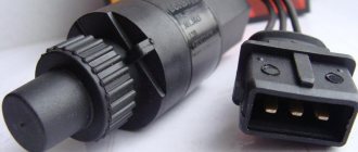
VS 5.1 (2111-1411020-72) ECU data is almost identical, differences in sensors, tuning options and R-83 standard (Euro 2 emissions standard) about the BOSH MP7.0H ECU (2111-1411020-40). I won’t tell you because they left later. and since we will connect to the computer from your Laptop, tablet, etc., we will need: the device itself from which we will look at the readings (smartphone, tablet, laptop, computer, it doesn’t matter) a special diagnostic cord (or just a bluetoch or wi-fi diagnostic adapter) Software for your device. in my case, this is a Laptop with Windows 10 Home, Vag-com KKL 409 diagnostic cord and OpenDiag 1.4 free software. (attention, these instructions are for a high panel) on the right side of the passenger, below the panel, you will find a diagnostic connector (in this case, GM12, I suggest throwing it out right away and not cutting the wires and buying an adapter, but buying an OBD II connector and installing it so that it is no longer possible bother) further, so as not to describe where, how and what to connect, I will attach a photo taken from the Internet for a detailed connection: we go into the car, look for the diagnostic block and hook up our wiring: Contact A - MOUNT (-) (black wire) Contact H - PLUS ( +) (yellow wire) Contact M - K-line (blue wire):
Front-wheel drive VAZ cars are very popular in Russia due to their high maintainability, relatively low cost of spare parts, and simple design. But due to the large number of modifications, it is not easy for the driver to understand even the instructions where this or that unit (part) is located, in particular, on the VAZ-21099 car the injector.
Read also: Licensing requirements for passenger transportation
Before repairing a car, some parts have to be searched for a long time and painstakingly, thus wasting a lot of time. In this article we will help you figure out where this or that device is located on the VAZ model 21099, and we hope that the information will be to some extent useful to car owners who have just bought a car, or to novice drivers.
Where is the fuel pump located on the VAZ-21099 injector
Removing and installing a gasoline pump (PG) is not a difficult job and does not require extensive plumbing experience or high qualifications. But if you don’t have to look for a fuel pump on carburetor cars for a long time (it is located on the engine, under the hood), then a beginner may not find it on the injector on the first try. Where is the fuel pump located on the VAZ-21099 sedan injector? Let's figure it out step by step:
- we move the front seats in the car forward as much as possible to free up space in the rear;
- open the rear left door of the car, find a small hinge on the rear sofa, which is located at the junction of the “seats” approximately in the middle of the cabin;
- pull the loop up, thereby raising the back of the lower seat;
- under the carpet we see the gas tank flap;
- unscrew the two fastening screws, remove the hatch and find the fuel pump underneath.
Useful video
You can learn more about how the scanner works in the video below:
In conclusion, it should be noted that using elm327 for the VAZ 2114 you can significantly save on car diagnostics and fix problems immediately after they appear (either on your own or at specialized service stations).
Diagnostic connectors VAZ
There are several types of connectors for diagnosing VAZ cars, including EURO 3 (4). To connect a car to a computer or laptop, you need to purchase or manufacture a communication interface between the COM port and the K-LINE diagnostic connector. It looks something like the picture below.
VAZ diagnostic connector for models after 2002 with an OBD-II connector
B L-line diagnostics
D CO potentiometer (not always diluted)
H Power supply +12V (not always wired)
G Fuel pump control (not always connected
M K-line engine diagnostics
Diagnostic connector for VAZ cars
H - 12V. Constant with battery via fuse A - GND B - L-Line M - K-Line G - Fuel pump control.
Diagnostic connector EURO 3
2 - J1850 Bus+ 4 - Chassis Ground 5 - Signal Ground 6 - CAN High (J-2284) 7 - ISO 9141-2 K Line 14 - CAN Low (J-2284) 15 - ISO 9141-2 L Line 16 - Battery Power
Location of diagnostic pads
VOLGA - under the hood, on the wall of the engine compartment, on the passenger side VAZ 2110 - to the right of the driver, next to the steering column of the VAZ 2109 Low panel - on the shelf under the glove compartment, next to the VAZ 2109 ECU High panel - behind the center console. VAZ 2108-2115 “Europanel” - on the dashboard, closed with a hatch. Chevrolet Niva - OBD-II, near the ignition switch. partially covered by the steering cover. VAZ 11183 “Kalina” - Under the niche for small items next to the gearshift knob. VAZ 21126 Priora - behind the glove compartment.
Where is the fan relay VAZ-21099 injector
Quite often a problem arises with the Ninety-Nine when the engine fan does not turn on and the coolant begins to boil. If such a malfunction occurs, first of all they check the functionality of the fan itself by applying voltage directly to it from the battery, but there may be other problems.
In order to check the entire circuit, it is important to find where the VAZ-21099 injector fan relay is located, since it is responsible for turning on the airflow. We find this part in the front of the car, on the passenger side, it is installed under the glove compartment, at the passenger’s feet.
The required relay in the picture is indicated by an orange circle, and here you will also find a fuse that blows when the cooling fan is short-circuited.
Video “Instructions for replacing the electronic unit in a VAZ 2115 yourself”
If you decide to replace the ECU, then this task can be done at home - detailed instructions for replacing the device yourself are presented in the video below (the author of the video is the AVTO CLASS channel).
Hi all!
I would like to tell you a little from
personal use about different types of ECUs for Samara for civilian driving on a stock engine, only the spider 4-1 is installed (standards e-2, respectively), the rest is all stock.
And so I bought my car with an M73
, the first batch was just in 2008, their production began.
Inherent jambs of the block, with low gas, that is, when driving over uneven surfaces in first gear, driving too fast because. xx speed of the M73 is 1100 rpm, if the speed is different from 0 km/h, and at a low throttle of 1-2% of the gas there is a twitching, sometimes it goes, sometimes it doesn’t go. This is typical only for 08-09 model years. Then, as I understand, judging by the reviews, things got back to normal with them. I tried various proprietary firmware (Norms e-2 only accordingly). The leader, as I believe, for the m73 open block (A(I)317DA02) This is Paulus. But Ledacol is not so bad. In principle, everything else is more or less normal, the plant is confident (autostart with a bang), the idle speed is more or less smooth (but not ideal), it drags only up to about 30-35% of the throttle, then the thrust comes to naught.
Where is the mass of the VAZ-21099 injector (main)
If the starter turns weakly, or the engine does not start at all (clicks occur when starting), various electrical problems arise, it is likely that the car does not have normal weight. Fixing such a problem is generally not difficult, but to do this you still need to know where the mass of the VAZ-21099 injector is located.
The main mass (thick) wire goes from the negative terminal of the battery to the engine, the thinner wire is connected to the car body, all energy consumers in the car depend on this connection. If the contact is poor, the battery stops charging normally; in order for the starter to turn well, you should check the reliability of these contacts and clean the metal from oxidation. If, due to a heavy load (for example, when installing additional equipment), the ground wire heats up and there is clearly not enough of it, you can “lay” additional ground almost anywhere where good contact between the engine and the body is ensured. The main thing is that this wire has a sufficient cross-section.
Read also: Hyundai Kia oil is fake
Engine compartment wiring VAZ-2109 (injector, carburetor): diagram
Cars of the VAZ family are practical vehicles, but the quality of manufacturing of individual mechanisms and systems leaves much to be desired. In this regard, owners of such machines often encounter all sorts of malfunctions and are forced to perform preventive repairs.
There are several categories of components in the design of a car that require close attention and attention.
These include:
- Brakes.
- Steering gear.
- VAZ-2109 engine compartment wiring and electrical network inside the cabin.
Therefore, it is important to understand that a breakdown in one of the above systems can have serious consequences for both the driver and passengers.
Vehicle handling
So, with the first two categories everything is very clear:
- Every owner understands what a loss of car control can result in.
- All identified breakdowns are immediately eliminated by repair or complete replacement of parts.
However, the wiring is not so simple. For some reason, everyone is accustomed to thinking that underhood wiring does not pose any danger. But this is a very big misconception.
The short circuit and ignition of live wires threatens that the car may simply burn out, explode, etc. And all this can happen both while parked and while driving.
Underhood wiring includes the following categories:
- Ignition system wires.
- Lighting systems, side lights.
- Connection system for sensors and control unit.
- Wires that are responsible for the operation of the electric motor of the radiator, washer, windows, and wiper.
If the wiring is in good condition, all current-carrying parts are insulated and qualitatively fixed in the engine compartment, taking into account all the necessary physical and temperature indicators of the internal combustion engine.
However, during vehicle operation, fastenings may deteriorate, which will entail:
- Loose contact.
- Destruction of insulation upon contact with hot surfaces of the engine and commutator.
- Formation of abrasions and exposure of wire cores.
- Oxidation of contact connections due to which the “mass” may disappear.
Most owners of the VAZ-2109, as well as other modifications of the domestic automobile industry, independently repair damage in which electrical tape is a direct participant. However, this is only a temporary solution and is not suitable for permanent operation of the machine. If there are problems with the wiring, the best way out of the situation is to completely replace it. According to the instructions, the harnesses must be laid in a corrugation, which is not the case on most machines.
Nuances of underhood wiring
There are quite a few hazards associated with wiring under the hood of a car that can affect its proper operation.
This place combines the most important systems and devices that have high physical and chemical properties:
- An internal combustion engine is a source of excess heat that “well” heats closely located components.
- Fuel system - explosive vapors of a mixture of air and gasoline.
- Power parts in the form of relays, electric motors, headlight ignition units and self-installed fog lights.
Accordingly, if the condition of the wiring is in poor condition or is deteriorating gradually, it is best to replace it. Otherwise there may be problems.
Where is the starter relay located?
Just like the engine cooling fan, the starter is controlled by a relay, and its malfunction can cause problems:
- when you turn the ignition key, nothing happens, the engine does not show any signs of life;
- When I try to start the engine, clicks are heard, but the starter does not crank.
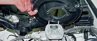
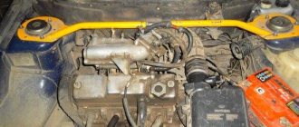
Finding out where the starter relay is located on a VAZ-21099i car is very simple; to do this, you just need to open the hood of the car and look behind the air pipe of the injection engine; the part you are looking for is shown below in the picture.
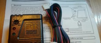
Where is the temperature sensor located?
If the temperature sensor does not show on the instrument panel, there is a high risk of overheating the engine, since the instrument panel does not inform the driver about the heating of the internal combustion engine coolant. Of course, the instrument panel or electrical wiring may be faulty, but most often the temperature sensor (DTOZH) on the engine itself refuses to work.
Where is the temperature sensor located on an injection car 099? Of course, you need to look for it in the engine compartment:
- open the hood;
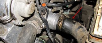
- we find the wiring that is located between the rear of the engine valve cover and the air filter housing;
- where the DTOZH is located can be seen in more detail in the following photos.
5.1.1 Injection system malfunctions
5.1.2. Injection system malfunctions
On VAZ-21083-20 vehicles in a variant with engines with a displacement of 1.5 liters, a distributed fuel injection system is used.
It is called distributed injection because fuel is injected into each cylinder with a separate nozzle. The fuel injection system reduces the toxicity of exhaust gases while improving the driving performance of the car. There are distributed injection systems with and without feedback. Moreover, both systems can have both imported and domestic components. All systems have their own design, diagnostic and repair features, which are described in detail in separate repair manuals for fuel injection systems.
This chapter only briefly describes the general principles of the design, operation and diagnostics of fuel injection systems, the procedure for removing/installing components, and also provides specifics for repairing the engine itself.
The feedback system is used mainly on export vehicles. In this case, an exhaust gas catalytic converter and an oxygen sensor are installed in the exhaust system, which provides feedback. The sensor monitors the concentration of oxygen in the exhaust gases, and the electronic control unit, based on its signals, maintains an air/fuel ratio at which the converter works most efficiently.
In the open-loop injection system there is no neutralizer and oxygen sensor; a CO potentiometer is used to adjust the CO concentration in the exhaust gases. The gasoline vapor recovery system is also not used.
Warnings
Before removing any components of the injection control system, disconnect the wire from the “–” terminal of the battery.
Do not start the engine if the battery cable terminals are not properly tightened.
Never disconnect the battery from the vehicle's on-board power supply while the engine is running.
When charging the battery, disconnect it from the vehicle's on-board power supply.
Do not allow the electronic control unit (ECU) to heat above 65 °C in operating condition and above 80 °C in non-operating condition (for example, in a drying chamber). It is necessary to remove the ECU from the car if this temperature is exceeded.
Do not disconnect or connect the wiring harness connectors from the ECU while the ignition is on.
Before performing electric arc welding on a vehicle, disconnect the wires from the battery and the wire connectors from the ECU.
Perform all voltage measurements with a digital voltmeter with an internal resistance of at least 10 MΩ.
The electronic components used in the injection system are designed for very low voltage, so they can easily be damaged by electrostatic discharge. To prevent damage to the ECU by electrostatic discharge: - do not touch the ECU plugs or electronic components on its boards with your hands; — when working with the programmable read-only memory (PROM) of the control unit, do not touch the pins of the microcircuit.
It is not allowed to operate an engine with a neutralizer on leaded gasoline. This will lead to rapid failure of the neutralizer and oxygen concentration sensor.
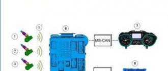
Injection system diagram
| 1. Air filter. | 16. Drain line. |
Engine compartment of a car with an injection system
| 1. Ramp with nozzles. |
Diagnostics
Here we provide only brief information on diagnosing the injection system using the CHECK ENGINE warning lamp. Diagnostics using special instruments and diagnostic cards are described in separate repair manuals for distributed fuel injection systems.
The ECU constantly performs self-diagnosis on certain control functions. The computer's language for indicating the source of a malfunction is diagnostic codes. Codes are two-digit numbers ranging from 12 to 61. The fault codes may differ slightly for different control units. The table shows the breakdown of fault codes for an electronic control unit of the “January-4” type for a distributed fuel injection system without feedback and with domestic components.
When the ECU detects a malfunction, the code is stored in “memory” and the CHECK ENGINE indicator light turns on. This does not mean that the engine must be stopped immediately, but the reason for the warning light to come on should be identified as soon as possible.
Fault codes for ECU type “January-4”
| Code | Malfunction |
| 12 | Indicator lamp diagnostic circuit fault |
| 14 | High signal level of the coolant temperature sensor |
| 15 | Coolant temperature sensor signal low |
| 16 | Increased voltage of the on-board network |
| 17 | Reduced voltage on-board network |
| 19 | Incorrect crankshaft position sensor signal |
| 21 | Throttle position sensor signal voltage too high |
| 22 | Insufficient throttle position sensor signal voltage |
| 24 | There is no signal from the vehicle speed sensor |
| 27 | High signal level of the CO potentiometer |
| 28 | Low signal level of the CO potentiometer |
| 33 | Incorrect signal from the mass air flow sensor (high frequency signal at the sensor output) |
| 34 | |
| 35 | Incorrect signal from the mass air flow sensor (low signal frequency at the sensor output) |
| 43 | |
| 51 | Unstable idle speed |
| 52 | Invalid knock sensor signal |
| 53 | Programmable read only memory (PROM) error |
| 61 | Electronic control unit (RAM) error Electrically programmable memory (EPROM) error Immobilizer communication error |
CHECK ENGINE lamp
The lamp is located on the instrument panel and performs the following functions: - informs the driver that a malfunction has occurred in the engine management system and the car needs to be checked; — issues diagnostic codes stored in the “memory” of the ECU to help a specialist find a malfunction.
When the ignition is turned on, the lamp lights up, and while the engine is not yet running, the serviceability of the lamp and systems is checked. After starting the engine, the lamp should go out. If the lamp remains on, the self-diagnosis system has detected a malfunction. If the malfunction disappears, the lamp usually goes out after 10 s, but the fault code will be stored in the “memory” of the ECU.
If the malfunction is intermittent, the CHECK ENGINE lamp will light for about 10 seconds and then go out. However, the corresponding fault code will be stored in the “memory” of the ECU until its power is turned off. When unexpected codes are found during the code reading process, it can be assumed that these codes are caused by an intermittent fault and will help in diagnosing the system.
Reading codes
The diagnostic block is used to communicate with the ECU. It is located under the instrument panel on the right side next to the ECU.
Trouble codes stored in the ECU's “memory” can be read using a special diagnostic tool or by counting the number of flashes of the CHECK ENGINE lamp.
To read the codes with a lamp, you must connect contact B of the diagnostic block to ground. To do this, connect it to pin A, which is connected to the engine ground.
A - contact connected to ground B - diagnostic contact for sending a signal to the computer G - electric fuel pump control contact M - information output contact (serial data channel)
When contacts A and B are connected, turn the key in the ignition switch to position I (ignition), but the engine should not be running. Under these conditions, the CHECK ENGINE lamp should flash code “12” three times in a row.
This should happen in this order: flash, pause (1-2 sec), flash, flash - long pause (2-3 sec) and so on two more times.
Code “12” indicates that the ECU diagnostic system is working. If code “12” is not displayed, then the diagnostic system itself is faulty.
After code “12” is displayed, the CHECK ENGINE lamp flashes fault codes three times, if they exist, or simply continues to display code “12” if there are no fault codes.
If more than one fault code is stored in the computer's memory, each of them is displayed three times.
Warning
Upon completion of the diagnostics, it is allowed to open contacts A and B of the diagnostic block 10 seconds after turning off the ignition.
Erasing codes
They erase codes from the ECU’s “memory” after completing repairs or to see if the malfunction occurs again. To erase, you must turn off the power to the computer for at least 10 s.
The power can be turned off by disconnecting the wire from the “–” terminal of the battery or by removing the ECU protection fuse from the fuse box.
Warning
To avoid damaging the computer, turn off and on its power only with the ignition off.
Distinctive features of injection systems
| Controller | General Motors | “January–4” |
| Controller markings | 2111–1411020–20 | 2111–1411020–22 |
| Catalytic converter | Eat | No |
| Crankshaft position sensor (Sensors are not interchangeable, check the specific number directly with your car) | 2112–3847010, 2112–3847010–01 | |
| Throttle position sensor (Sensors are not interchangeable, check the specific number directly with your car) | 2112–1148200, 2112–1148200–31 | |
| Air flow sensor | 2112–1130010–01GM, square body | |
| Temperature sensor (Sensors are not interchangeable, check the specific number directly with your car) | 2112–3851010, 2112–3851010–01, 2112–3851010–02 | |
| Knock sensor (Sensors are not interchangeable, check the specific number directly with your car) | 2121–3855010, 2121–3855010–01, 2121–3855020 | |
| Speed sensor (Sensors are not interchangeable, check the specific number directly with your car) | 2112–3843010, 2112–3843010–20, 2112–3843010–30, 2112–3843010–31, all with round connector | |
| Oxygen sensor | 2121–3850010–11, 2121–3850010–20, type GM AFS–62, AFS–79, Bosch LHS–24 | No |
Injection system sensors
What are the consequences of malfunctioning injection system sensors:
— crankshaft position sensor
— complete failure of the injection system, the engine does not start;
— mass air flow sensor
— increased fuel consumption, significant deterioration in dynamics, problems with starting the engine;
— throttle position sensor
— loss of power, jerks and dips during acceleration, unstable operation in idle mode;
— coolant temperature sensor
— difficulties with starting in cold weather: you have to warm up the engine by operating the gas pedal, when overheating the power is significantly reduced and detonation appears;
— knock sensor
— the engine is very sensitive to the quality of gasoline, increased tendency to detonation.
Features of electrical equipment of cars with distributed fuel injection with feedback
| 1. Throttle position sensor. 2. Crankshaft position sensor. 3. Coolant temperature sensor. 4. Speed sensor. 5. Canister purge valve. 6. Mass air flow sensor. 7. Knock sensor. 8. Oxygen concentration sensor. 9. Blocks of the electronic control unit. 10. Ignition relay. 11. Fuses. 12. Relay for turning on the electric fuel pump. 13. Diagnostic block. | 14. Idle speed regulator. 15. Block for connection to the instrument panel wiring harness. 16. Display with CHECK ENGINE indicator lamp. 17. Mounting block. 18. Electric motor of the engine cooling system fan. 19. Electric fuel pump with fuel level sensor. 20. Injectors. 21. Spark plugs. 22. Ignition module. A. To the “+” terminal of the battery. B. To terminal “15/1” of the ignition switch. C. To the low-voltage tachometer input on vehicles with a “high” panel. K9. Fan motor relay. |
Where is the speed sensor located?
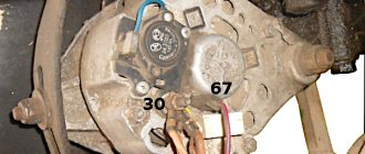
The speed sensor (DS) on front-wheel drive VAZ cars reads pulses depending on wheel speed and transmits the data to the electronic control unit (ECU). When braking the engine, the fuel supply is turned off with the help of the diesel engine and the computer, thus achieving more economical operation of the internal combustion engine. If the sensor is faulty, an error code is recorded, gasoline consumption increases slightly, and idle speed decreases, especially during heavy braking. It is difficult to immediately detect where the speed sensor is located, since it is hidden under the air filter housing (AFC).
We find the part we need as follows:
- open the hood of the car;
- Using a 10mm wrench, unscrew the two KVF fastening bolts;
- loosen the clamp of the air “corrugation”, disconnect the “chip” with the wires;
- we take out the KVF, now the sensor has already appeared in the field of view, it is located on the gearbox (gearbox) housing, wires are connected to it, connected using a connector.
The DS can be easily unscrewed by hand, and the plug with wires can be pulled out even after the sensor has been unscrewed (but carefully so as not to damage the wiring during rotation).
Computer diagnostics
If you carry out scanning diagnostics using the appropriate equipment, you can understand from the detected errors that the ignition module is faulty.
- P3000
(and also 3001-3004) – the ignition in the cylinders does not work; - P0351
– winding break in a pair of 1/4 cylinders; - P0352
– winding breakage in a pair of 2/3 cylinders.
If you discover any of these errors using a smart machine, do not rush to get too upset, since they do not necessarily indicate the death of this node.
For example, high-voltage wires with breakdown or spark plugs can also create a problem. Therefore, professional diagnosticians advise going from small to great: that is, at the beginning, exclude more correctable and minor symptoms, taking on large and global ones last. And only after checking other elements of the ignition system for malfunctions: unscrewing and inspecting the spark plugs, for example, ringing and replacing the wires, then start diagnosing the problems of the corresponding module.
Where is the fuel filter located?
The fuel filter (TF) on the VAZ-21099i is designed to clean gasoline from debris, dirt and various impurities; it is a monolithic structure with a rigid metal body and a filter element inside. The frequency of its replacement is every 20-30 thousand km of the distance traveled, also if the car begins to move jerkily, and diagnostics showed that the fuel pump is clogged.
It’s easy to find out where the fuel filter is located; to do this, you need to install the car on an inspection hole or a car lift. The TF is located on the bottom of the body, next to the rear beam and the gas tank, and is secured with a special clamp, which is tightened with a bolt and nut.
Read also: Advocam fd8 gold gps review
Before you start changing the filter, you need to relieve the fuel pressure, otherwise when you unscrew the fuel fittings, gasoline will splash under high pressure. You can relieve pressure in the line using a special nipple located at the rear of the fuel rail. Before starting such an operation, it is necessary to prepare a plastic container into which gasoline should be poured, then unscrew the safety cap.
To release the pressure, you can use a standard flat-head screwdriver; when you press the nipple valve, gasoline will come out of the system.
After removing fuel from the line, we proceed to replacing the fuel pump.
Related articles:
- The VAZ-2109 starts and stalls: causes of malfunction, solution to the problem The VAZ-2109 model with a carburetor engine is an unpretentious Russian car, characterized by a low price, economical fuel consumption, high maintainability, very good […]
- Front spar of the VAZ-2109 - replacement, repair, cost of work The VAZ-2109 is a car that does not have a strong body; iron corrodes quite quickly, and almost all body parts rust. Replacement of the front side member is required […]
- Self-repair of the underbody of a VAZ-2110 car The car body is subject to corrosion over the years, and it begins to rust especially quickly if you do not take care of it and do not apply an anti-corrosion coating. How soon do they begin to cover […]
What to do if there is no working module?
If it is not possible to install a test element or borrow it for a while, for example, from a neighbor in the garage, then you will have to be patient and pick up a test lamp and a multitester.
We measure the resistance between the winding terminals (paired). The probes must be installed according to the scheme: 1/4, 2/3. The measurement results should be almost identical (approximately 5.5 kOhm is shown by the device). If the errors between them are 100 Ohms or more, the module needs to be replaced, since the secondary winding has failed. Next, in order to identify signs of a malfunction in the ignition module of the VAZ 2110 and 2114, we call the wire block and check the serviceability of the ECU. If you don’t have a multitester at hand, some testing steps can be carried out using a test light.
One thought on “Location of components and parts on the injection car VAZ-21099”
I have a fan relay on a 2109 injector, located to the left of the one marked in the photo
On injection systems of engines of VAZ 2108, 2109, 21099 cars, the controller (ECU, control unit) is a device that coordinates the operation of all sensors and systems included in the ECM. This is a specialized mini computer in which an engine control program is installed. Let's consider the applicability of controllers on VAZ 2108, 2109, 21099.
VAZ 2108, 2109, 21099 with engine 2111 without converter, with CO potentiometer (device for manual adjustment of CO content in exhaust gases), until 2001 (emission standards R-83):
— BOSH M1.5.4 (2111-1411020);
- January 4.1 (2111-1411020-22).
VAZ 2108, 2109, 21099 with engine 2111 without a neutralizer, without a potentiometer, but with the ability to electronically adjust CO using a scanner or a technological, plug-in potentiometer, since 2001 (toxicity standards R-83):
— BOSH M1.5.4 (2111-1411020-70);
— January 5.1 (2111-1411020-71);
- VS 5.1 (2111-1411020-72).
VAZ 2108, 2109, 21099 with engine 2111, with neutralizer, one oxygen sensor, gasoline vapor recovery system (EURO-2 standards):
— GM ISFI-2S (2111-1411020-10 (20, 21));
— BOSH MP7.0N (2111-1411020-40);
— BOSH M1.5.4N (2111-1411020-60);
— January 5.1 (2111-1411020-61);
- VS 5.1 (2111-1411020-62).
VAZ 2108, 2109, 21099 with engine 2111, with a neutralizer, two oxygen sensors (control and diagnostic), a gasoline vapor recovery system (EURO-3 standards):
— BOSH MP7.0N (2111-1411020-50).
Notes and additions
— Controllers GM ISFI-2S (2111-1411020-10 (20, 21)), January 4.1 (2111-1411020-22), BOSH M1.5.4 (2111-1411020) are currently discontinued.
More articles on the VAZ injector
Wiring diagram VAZ-2109 injector with high and low panels: description, photo
VAZ-2109 8 valves should first of all be considered as equipment that needs constant monitoring and inspection of its technical condition. If a car owner independently maintains his iron four-wheeled friend, then he must know how all car components work, including electronic elements. It is the electronic components in the VAZ-2109 injector that ensure uninterrupted operation of the engine, and if any element fails, the car will not be able to cope with its main responsibilities. Understanding the operating principle of the engine control system and identifying the cause of a malfunction in it is quite simple if the car owner familiarizes himself with the electrical circuit for the VAZ-2109 injector.
What kind of problems does an electrical circuit help to solve?
The electrical circuit for the VAZ-2109 injector is, of course, several times more complicated than for carburetor cars. However, this is not at all surprising, because models with distributed fuel injection have numerous electronic devices built into them, which, unfortunately, can fail. An interactive diagram helps solve many problems:
- provides the driver with information about the functionality of all electronic devices;
- transmits a control pulse to electronic elements;
- acts as electrical protection for all electronic devices;
- protects the system from short circuits.