Classification and standard configuration of immobilizers on Hyundai Getz
From 1998 to 2004, the car was produced with contact-type anti-theft protection, but subsequent models began to be produced with a contactless operating principle. Contactless immos have proven themselves to be more reliable devices.
The standard immobilizer configuration in the Hyundai Getz consists of the following logical components:
- Electronic control unit. It gives an impulse when the ignition is turned on with the chip key and allows the engine to start.
- Electromechanical relay. It is the control element in the ignition system. The relay is activated by the immobilizer control unit.
- Antenna for receiving key tags. Installed in the electronic ignition unit to receive a signal from the chip key.
- Chip key. The car key contains a chip that controls the immobilizer.
Where are the immobilizer parts located?
To protect against theft, the control unit on the car is installed in a niche of the instrument panel behind the dashboard, so that an attacker cannot damage it and steal the car.
Location of immobilizer components
Radio-controlled relays for blocking the starter and fuel pump are mounted in the engine compartment. The fuel pump relay is located next to the battery. A standard engine start relay is located near the starter. Relay equipment is installed in a niche in the luggage compartment, which is involved in stabilizing fuel pressure.
Location of fuses under the hood
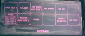
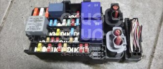
Mounting block located in the engine compartment: 1 - interior heater fan relay E 51; 2 - location for the relay for turning on the engine cooling system fan at high speed E 44; 3 - relay for switching on the engine cooling system fan at low speed E 43; 4 — starter relay E 41; 5 — space for air conditioning relay E 50; 6 — sound signal relay E 45; 7 - fuel pump relay E 49; 8-13 - fuses and fuses"; 14 — space for the E 47 security alarm relay; 15-27 - fuses and fuses; 28 — tweezers for replacing fuses; 29 — connecting connector E 55; 30 - power relay for electronic engine control system E 42
A more detailed position and purpose of each fuse is shown here
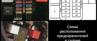
Mounting block located inside the car: 1-29 - fuses and fuses; 30 — tweezers for replacing fuses; 31 - spare fuses
Factory SMARTRA system
The BOSH campaign has developed an electronic control unit for Hyundai cars called SMARTRA. The ignition system is controlled by the immobilizer module. The manufacturer assigned each car its own electronic code, the value of which coincides with the ignition key. The principle of operation is to transmit a code to all elements that are involved in starting the engine.
Reasons for turning off the factory system
Failure to start the engine causes the immobilizer system to fail, even when using the original chip key.
The main reason is the following malfunctions:
- an antenna that has stopped transmitting a signal to radio-controlled relays;
- there is no contact in the relay;
- oxidation of control unit connectors.
To more accurately determine the reason for the SMARTRA system shutdown, it is necessary to perform computer diagnostics at a service center.
The video shows signs of a malfunction of the immobilizer system from the Androll1 channel.
Hyundai Solaris fuse box
Cars sedan, hatchback 1.4, 1.6 l 2011, 2012, 2014, 2020 produced
Where are the fuses and relays located for the Hyundai Solaris?
In the mounting block of the engine compartment - number 11
To get to the fuses, you need to press the latches and open the cover
On the inside of the cover of the fuse and relay mounting block there is a diagram of the arrangement of the elements.
Inside the mounting block there are tweezers for removing fuses.
The main fuse is installed on the side wall of the mounting block.
Replacement of fuses is done with tweezers, the relay is changed by hand.
The fusible links in the main fuse located on the side wall of the mounting block have this arrangement.
| Fusible link number | Current strength, A | Protected circuit |
| 1 | 50 | Tail light relay |
| 2 | — | Reserve |
| 3 | — | Reserve |
| 4 | 125 | Generator |
| 5 | 40 | Hydroelectronic ABS module, diagnostic connector |
| 6 | 40 | Hydroelectronic ABS module |
| 7 | 40 | Heated rear window relay |
| 8 | 40 | Fan relay hyundai solaris |
| 9 | — | Reserve |
The Hyundai solaris mounting block itself is under the hood with the lid open.
Decoding
| Fuse, fuse and relay number | Current strength, A | Color | Purpose |
| 1 | — | — | Reserve |
| 2 | — | — | Reserve |
| 3 | 15 | Blue | Fuel module |
| 4 | 10 | Red | Hyundai solaris horn |
| 5 | 50 | Red | Power windows, hazard warning switch, central locking |
| 6 | 40 | Blue | Heating system control unit |
| 7 | 30 | Red | Electronic engine control unit |
| 8 | 40 | Blue | Ignition switch, engine start and stop button |
| 9 | 50 | Red | Ignition switch, engine start and stop button |
| 10 | 10 | Red | Air conditioner |
| 11 | — | — | Reserve |
| 12 | — | — | Reserve |
| 13 | 15 | Blue | Supply system |
| 14 | 10 | Red | Camshaft Position Sensor, Oxygen Concentration Sensor |
| 15 | 10 | Red | Electronic engine control unit |
| 16 | — | — | Reserve |
| 17 | 10 | Red | Instrument cluster, tail lights |
| 18 | — | — | Reserve |
| R1 | — | — | Reserve |
| R2 | — | — | Hyundai solaris horn relay |
| R3 | — | — | Ignition switch relay, engine start and stop buttons |
| R4 | — | — | Air conditioner relay |
| R5 | — | — | Ignition interlock switch relay |
| R6 | — | — | Fan Relay (Low Speed) |
| R7 | — | — | Fan Relay (High Speed) |
| R8 | — | — | Diagnostic connector relay |
| R9 | — | — | Hyundai solaris ignition switch relay |
| R10 | — | — | Ignition switch relay, engine start and stop buttons |
| R11 | — | — | Emergency Brake Warning Relay |
| R12 | — | — | Engine control unit relay |
| R13 | — | — | Fuel pump relay |
| R14 | — | — | Reserve |
| R15 | — | — | Radiator fan relay |
Fuses in the mounting block in the Hyundai Solaris interior.
Located in the instrument panel. To get there, you need to pry the recess in the decorative cover with your fingers and, overcoming the force of the latches, remove it.
Decoding
| Number | Current strength, A | Name | Color | Protected circuit |
| 1 | 15 | FRT Deicer | Blue | Heated windshield |
| 2 | 15 | P/QUTLET | Blue | Socket for connecting additional equipment |
| 3 | 15 | C/UGHTER | Blue | Cigarette lighter fuse hyundai solaris |
| 4 | 10 | ACC | Red | Egnition lock |
| 5 | 10 | A/BAG IND | Red | Front airbag deactivation warning light |
| 6 | 10 | D/BAG | Red | Airbag hyundai solaris |
| 7 | 10 | T/SIG | Red | Hazard switch |
| 8 | — | — | — | Reserve |
| 9 | — | — | — | Reserve |
| 10 | 15 | R/WPR | Blue | Windshield wiper and washer switch lever |
| 11 | — | — | — | Reserve |
| 12 | 10 | R.R. | Red | 'Rear fog light |
| 13 | 10 | FRT | Red | Front fog lights |
| 14 | 10 | ROOM 2 | Red | Battery Saver Relay* |
| 15 | 15 | STOP LP | Blue | Brake lights |
| 16 | 10 | CLUSTER | Red | Instrument cluster hyundai solaris |
| 17 | 10 | IG1 1 | Red | Security control module |
| 18 | 10 | ABS | Red | Hydroelectronic anti-lock braking system module |
| 19 | 10 | B/UP LP | Red | Reversing light switch |
| 20 | 10 | PCU | Red | Immobilizer |
| 21 | 10 | H/LP LFI | Red | Left headlight |
| 22 | 10 | DAYTIME RUNNING LIGHT | Red | Daytime Running Lights |
| 23 | 15 | HAZARD | Blue Grey | Hazard switch |
| 24 | 25 | SMKJ | Electronic key control module | |
| 25 | — | Reserve | ||
| 26 | 10 | SMK2 | Red | Engine start/stop button |
| 27 | 15 | TCU | Blue | Vehicle speed sensor |
| 28 | 15 | IGN COIL | Blue | Ignition coils |
| 29 | 10 | IGN 2 | Red | Power windows, sunroof |
| 30 | 25 | F/WPR | Grey | Windshield wiper |
| 31 | 20 | DOOR LOCK | Yellow | Door lock control unit |
| 32 | 25 | SAFETY P/WDW | Grey | Locking power windows |
| 33 | 15 | S/HEATER | Blue | Electrically heated front seats Hyundai Solaris |
| 34 | — | — | — | Reserve |
| 35 | 10 | ROOM 1 | Red | Interior lighting, air conditioning |
| 36 | 20 | AUDIO | Yellow | Audio system |
| 37 | 10 | TAIL LFI | Red | Rear left lamp, license plate lamps, left headlight |
| 38 | 10 | TAIL Rl-I | Red | Right tail light, right headlight |
| 39 | 10 | START | Red | Starter relay, anti-theft alarm |
| 40 | 10 | H/LP RH | Red | Right block headlight |
| 41 | 25 | P/WDW LH | Grey | Power window control unit, left rear power window switch |
| 42 | 25 | P/WDW RH | Grey | Power window control unit, right rear power window switch |
| 43 | 10 | HTD MIRR | Red | Heated exterior mirrors |
| 44 | 10 | A/CON_2 | Red | Air conditioner hyundai solaris |
| 45 | — | — | — | Reserve |
How to remove the main fuse
Unscrew the two nuts and remove the wire ends from the studs of the mounting block
Use a screwdriver to pry and remove the main fuse
Removing and installing the mounting block in the Hyundai solaris interior
Disconnect the wire from the negative terminal of the battery
Remove the lower trim of the instrument panel
Fold out the fixing bracket
Disconnect the wiring harness block from the mounting block. Similarly, disconnect the upper block of the wiring harness.
Press the latch and disconnect the side block of the wiring harness
Using a screwdriver, pry and remove the diagnostic connector from the mounting block mounting bracket
Press the fastening clamp and disconnect the relay from the right wall of the mounting block.
Similarly, disconnect the lower
and the upper block of wiring harnesses from the left wall of the mounting block
Unscrew the two nuts securing the mounting block
Move the mounting block aside and disconnect the three rear wiring harness connectors.
Remove the fuse mounting block
Where is the diagnostic connector for Hyundai Solaris?
It is located inside the car in the instrument panel, near the fuse box.
The most common problem with immobilizers: malfunction of the antenna
Signs of a malfunction may include:
- the engine does not start at all or after the second and third try;
- a check indicating a malfunction of the immobilizer system is lit on the instrument panel;
- unstable operation of the injection system.
Causes of malfunction
The following factors may cause malfunction of the control unit antenna:
- increased humidity in the car interior;
- oxidation of contact connections and connectors;
- mechanical damage during repair of a dashboard or car body.
Carrying out repairs yourself
Before repairing, you need to prepare the tool:
- Phillips and flat head screwdriver;
- pliers;
- needle file;
- a set of clock screwdrivers and hexagons;
- marker;
- multimeter
Clamp meter with built-in multimeter
Needle file
Repairs are carried out in the following order:
- The machine is installed in a garage or on a site.
- Disconnect the battery terminal.
- Since the antenna is installed in the ignition cylinder, the steering wheel covers must be removed using a flat-head screwdriver.
- Dismantling the ignition switch is done with a hand tool. The connectors are marked with a marker for proper assembly. It is necessary to unscrew the three fastening screws and carefully remove the lock block from behind the rubber curtain.
- The connection connectors are located deep behind the dashboard. It is necessary to cut through all the straps with side cutters in order to remove the ignition module. Disconnect the connector by pressing the latch. The contacts are cleaned using a thin file and lubricated.
- An antenna is installed at the end of the lock, which is secured with three screws. You need to unscrew them using hexagons.
- Replace the element and check with a multimeter for correct installation.
- Reassembly occurs in the reverse order, then the engine is started.
Location of fuses under the hood
Mounting block located in the engine compartment: 1 - interior heater fan relay E 51; 2 - location for the relay for turning on the engine cooling system fan at high speed E 44; 3 - relay for switching on the engine cooling system fan at low speed E 43; 4 — starter relay E 41; 5 — space for air conditioning relay E 50; 6 — sound signal relay E 45; 7 - fuel pump relay E 49; 8-13 - fuses and fuses"; 14 — space for the E 47 security alarm relay; 15-27 - fuses and fuses; 28 — tweezers for replacing fuses; 29 — connecting connector E 55; 30 - power relay for electronic engine control system E 42
A more detailed position and purpose of each fuse is shown here
Mounting block located inside the car: 1-29 - fuses and fuses; 30 — tweezers for replacing fuses; 31 - spare fuses
Getz standard system errors
Using computer diagnostics or a diagnostic wireless connector, you can determine the problem of starting the car engine. Errors will be presented as code.
Loading …
The interpretation of Hyundai Getz immobilizer error codes is presented in the table.
| Error code | Decoding |
| P1690 | SMARTRA immobilizer malfunction |
| P1691 | The antenna is damaged or there is no signal |
| P1693 | Immobilizer transponder malfunction |
| P1694 | Immobilizer blocking engine start |
Fuel pump system on Solaris
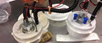
The fuel module is part of the vehicle's fuel supply system, which also includes a gas tank, pipelines and a fuel rail with injectors.
The Hyundai Solaris fuel module includes:
- Electric motor.
- Coarse fuel filter.
- Fine fuel filter.
- Fuel pressure control.
- Fuel level sensor.
Signs of a faulty fuel pump
If the fuel pump malfunctions, the following symptoms appear:
- The car does not start the first time or does not start at all.
- The car stalls when stopping.
- The engine runs rough both at idle and when driving, especially on an incline or during sudden acceleration.
- Fuel consumption increases.
Basic fuel pump faults
Among the main problems that arise during the operation of the fuel pump are usually clogging the filter, breakdown of the motor and damage to the fuel pump housing.
How much does a Hyundai Solaris fuel pump cost?
The original Hyundai Solaris fuel pump (catalog number 311101F9809) costs 11,000 rubles. Analogs will be cheaper, for example, the price of a pump produced by Bosch is 4,000 rubles. The fuel pump mesh (catalog number 310902D100) costs 200 rubles.
Unlike many cars, Hyundai allows you to change the filter without replacing the pump.
Symptoms of a faulty fuel pump
Actually, these are rather two stages of the same malfunction, although it happens that malfunctions in the operation of the fuel pump do not lead to its complete failure. Especially when these failures are caused by some extraneous factors. And so, the fuel pump either simply fails or does not work at all. These are all his breakdowns. Another thing is that there are many breakdowns of other elements, which in their symptoms are very similar to fuel pump breakdowns.
As for the signs of a fuel pump malfunction, there can be a lot of them, and as already mentioned, they may coincide with symptoms of problems in other components and systems of the car. Therefore, we will describe only the most common and most characteristic of these symptoms.
- the car does not start or stalls frequently;
- engine troits;
- extraneous noise in engine operation;
- drop in engine power;
- absence of characteristic noise when the fuel pump operates;
The signs are very eloquent, but it’s not always possible to understand what they are talking about. And here we cannot do without methods for diagnosing the fuel pump.
Preventing fuel pump malfunctions
What should you pay attention to so that the fuel pump runs as long as possible? First of all, this is the quality of the fuel and, of course, timely replacement of the fuel filter. If the gasoline you fill contains various foreign inclusions, this will most likely negatively affect the condition and service life of the fuel pump, and not only it. Therefore, it is not worth saving on the quality of fuel, since such savings then result in very significant expenses for car repairs.
Monitor the fuel level in the tank. The fact is that the fuel pump is cooled by the same gasoline that it pumps. Accordingly, if there is little fuel, or the pump runs idle, it may overheat and therefore fail. Knowledgeable people also advise cleaning the gas tank at the appropriate time and not neglecting this procedure. This is, perhaps, all the prevention of problems with the fuel pump.
Layout diagram
The Hyundai Solaris has two fuse blocks. One of them is located directly in the cabin. There are those fuses that can quickly lose their functionality. Accordingly, in the event of a breakdown, you will not need to climb under the hood of the car. To gain access to the block, simply remove the decorative trim using a screwdriver.
The second block is located directly under the hood. It is located on the right side of it. The block is protected by a plastic cover, which can also be removed using a screwdriver. Like any other element, it can become unusable, so it is important to know the location of each of the fuses.
The diagnostic connector is located inside the car. You can find it right in the instrument panel, next to the fuse box. To correctly select and replace fuses, you can rely on special diagrams. The original diagram can always be found on the lid. If it was replaced, you will have to use a schematic representation of the arrangement of elements proposed below.
