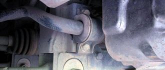
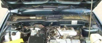
A vehicle speed sensor (VS) is necessary to measure the speed of a vehicle. The readings from the sensor are transmitted to the electronic control unit (ECU), which controls the engine and adjusts engine operation. On the vast majority of cars, the speed sensor is located directly on the gearbox, closer to the speedometer drive mechanism.
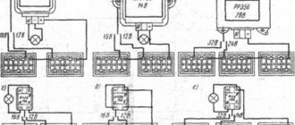
Among the main malfunctions of the DSA are: open circuits, damage or oxidation of contacts, failure of the sensor itself, malfunction of the speed sensor drive. If malfunctions occur, the speed sensor is checked with and without dismantling:
- multimeter (measuring signals within the operating cycle);
- using a control lamp;
Detailed information about the signs of a malfunctioning speed sensor, as well as how to check it, is presented in our article.
Speed sensor on a car: where is it located?
The speed sensor is located on the gearbox, in the area of the speedometer drive mechanism. The main task of the vehicle speed sensor (VS) is to measure speed, after which this information is transmitted to the ECU.
Having received a signal from the DSA, the electronic unit regulates the idle speed, controls the amount of air entering the engine, and also changes a number of other parameters. The faster the car moves, the higher the frequency of the signals transmitted from the speed sensor.
How to trick a computer
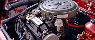
First, let's imagine the operation of an injection engine: the engine rotates and at the same time sucks in clean air through the intake manifold. Near the intake valves, gasoline is injected into this air through a fuel injector. The amount of gasoline depends, as mentioned above, on the pressure in the fuel line, which remains almost unchanged, increasing with load by about 0.5 kg/cm2, which is quite a bit; as well as the time during which the injector will be open. In other words, the amount of gasoline supplied to the cylinders depends on the width of the pulses generated by the computer. The computer sets this width based on data from several sensors. Coolant temperature sensor: the hotter the engine, the less gasoline is needed, so this sensor changes its resistance depending on the temperature, letting the computer know what condition the engine is in. Typically, the resistance of a cold sensor is 5-10 kOhm, and a hot sensor is 200-500 Ohm.
If you solder a regular 2-3 kOhm resistance parallel to the standard sensor, the computer will assume that the engine is hotter than it actually is and, accordingly, will reduce the width of the triggering pulses. You may be tempted to short-circuit this sensor altogether, but in this case, an engine fault signal is generated in the computer, the “SNESK” light or the display with the image of the engine lights up, and the engine may stop altogether (the same will happen when the connector is removed from the sensor, i.e. i.e. when resistance appears more than 20-30 kOhm). If you install an additional resistance of about 500 Ohms, then due to a lack of gasoline, the engine will work very poorly until it warms up completely. It is best to install a variable resistance and, with its help, adjust the sensor readings so that the malfunction light on the instrument panel does not light up, the engine starts more or less normally and runs in a cold state, but it “eats” less gasoline (this can be determined by the color of the exhaust gases, but it’s better to use a gas analyzer). After this adjustment, you can unsolder the variable resistance, measure it with a tester, select the same regular resistance and solder it permanently.
The air temperature sensor has approximately the same resistance ranges as the water temperature sensor: from 200 Ohms when hot to 10 kOhms when cold. But the computer takes air temperature into account much less than water temperature. There are two wires that go to both sensors, both of them have latches, so you can’t pull them off so easily. When you remove any of them, the “SNESK” light (or another emergency light, for example, with a picture of an engine) will light up on the display. The fluid temperature sensor is usually screwed into the top of the engine, always in a small cooling circuit, usually near the thermostat. In addition to it, there may be sensors for a dial temperature indicator, an emergency light for engine overheating, starting a fan, starting a cold engine and an air conditioning control unit. The air temperature sensor can be screwed into the air filter, into the air pipe before or after the throttle body, or into the intake manifold.
But these sensors, even both taken together, only have a small influence on the computer’s decisions about the width of control pulses; the main role in this belongs to the sensor that shows the amount of air entering the cylinders. As mentioned above, during operation the engine sucks in air through the air filter, air duct and intake manifold (maybe also through the turbine and INTERCOOLER cooler). When (with the gas pedal released) the throttle valve is completely closed, air enters the engine through the idle passage, which is closed by the idle screw. When the engine is cold, a special bellows or valve opens the warm-up speed channel by a certain amount. If you turn on something, like the air conditioning, another special valve, controlled by a computer, will open and more air will flow into the engine through another air channel. All air is “calculated”, and the computer, knowing the amount of this air, will generate the required pulse width. Air quantity meters can be very different, they can work based on a variety of principles (there are mechanical, thermal, etc.), but there is almost always an air channel that bypasses these “readers”.
“Uncalculated” air passes through this channel, unaccounted for by the computer, and the computer will not “splash” gasoline under it. This channel is closed with an adjusting screw: by unscrewing the screw, you can add raw air to the intake manifold, i.e. you can make the mixture leaner. The mixture can be made even leaner by making an additional bypass channel using a rubber tube. In this case, the “counter” will measure only part of the air entering the engine, supplying the computer with a reduced voltage, and the computer will, as a result, generate shorter pulses to start the injectors, which, naturally, will spray gasoline for a shorter period of time.
It is quite obvious that it is very easy to fool a computer with air measurements. Yes, he himself is deceived, because... There is moisture, acid, and dust in the air, which significantly distort the operation of the “reading machine,” which is why new cars do not have these devices, but rather have vacuum sensors. Small, completely sealed, only three wires and a rubber tube fit into them, and inside there is a micro-assembly, i.e. small computer. This sensor measures the amount of vacuum in the intake manifold and lets the computer know about it. The latter, knowing the engine speed and the position of the throttle valve, on which there is also a sensor - a variable resistor, calculates how much air is flowing in at the moment, and accordingly determines the width of the injector trigger pulses. To make these pulses shorter, you need to insert two additional resistances. The Vacuum sensor has three wires: power, housing and signal. It is necessary to break the power circuit (it contains 5 volts) and the signal circuit and solder variable resistances into the gaps.
We set both resistances to 0 ohms and start the engine. Now, quickly, before the engine warms up, we increase the resistance in the power wire until malfunctions appear in the engine. We turn off the engine, measure the variable resistance and replace it with a standard resistance of the same or slightly lower value. It will turn out from 3 to 10 ohms. We start the cooled engine again and turn the variable resistor in the signal circuit, repeating the steps in the same way. But in this case, the resistance will be about 20 kOhm (however, the resistance values are not important for you, the engines are different, and you may end up with not 20, but 10 kOhm, or another value). After such a “modification,” the engine may work a little worse in an unheated state, but after warming up everything will be fine.
How to figure out where the signal wire is and where the power is? Sharpen the probe on the tester and, piercing the insulation of each wire (the ignition should be on), measure the voltage relative to the body: there will be 5 volts on the power wire, almost 5 volts on the signal wire, and 0 volts on the body. Now disconnect the rubber tube from the intake manifold leading to the vacuum sensor and create a vacuum in it with your mouth. The voltage in the signal wire will immediately decrease, but the voltage in the power wire will remain the same. Of course, not because of a good life, wanting to save fuel, we subject the control unit of an imported car to “violence” and, of course, we do not at all urge everyone to immediately start “modernizing” their cars. We offer the above as a way out of a situation where black smoke is pouring out of the exhaust pipe, and there is no other computer. But at the same time, gas analyzers, voltmeters, etc. should be at hand. The result of this modernization has been tested in practice: 13 liters of gasoline per 100 km in the city for a Plymouth with a 2.3-liter Twincam engine and an automatic transmission, you see, is not so bad, but before the “modernization” it was more than 20 liters and Black smoke was coming from the exhaust pipe.
Blue smoke.
The reasons for the appearance of blue exhaust gases are the same as for carburetor engines. But if the engine is equipped with a turbocharger, there may be several other reasons, based on a “dead” turbine. Turbochargers are lubricated during operation by engine oil from the engine lubrication system. If the seals on the turbine-compressor shaft are already worn out (this happens quickly when the bearings are worn out), oil begins to seep out. On the one hand, it enters the compressor, and then, together with the air, is supplied to the intake manifold. On the other hand, the oil enters the turbine, where it instantly turns into blue smoke and is thrown out. From practice it follows that the turbine seal deteriorates faster. But there are some peculiarities here. Firstly, the smoke in this case is not completely blue, but somewhat gray. Secondly, the engine begins to smoke only after warming up, and the smell of exhaust gases is interrupted by the smell of burnt oil. In addition, sometimes, when the engine is running for a long time in a cold state, oil may even drip from the exhaust pipe.
White smoke.
The reasons for its appearance are the same as for carburetor engines. Cars with diesel engines have blue exhaust gases for the same reasons as cars with gasoline engines. The same can be said about the appearance of white exhaust gases. But, in addition, there is another interesting reason for white exhaust from diesel engines. More about it a little later, but for now remember the documentaries in which tanks put up a smoke screen during exercises. They do this by feeding diesel fuel into the hot exhaust manifold (that’s all, what an effect!).
Black exhaust from diesel engines occurs when diesel fuel is incompletely burned. This can happen if the fuel is not mixed well with the air, and this happens when the gas pedal is fully depressed with a high fuel supply. In this case, a slightly defective injector is not able to properly atomize the fuel so that it burns completely. But we believe that when a diesel engine is overloaded, black exhaust is normal. Moreover, the presence of black smoke indicates that there is enough fuel supplied, i.e. all filters in the system are operational. In a car with a “clogged” fuel filter, in addition to a decrease in power, there is no black smoke when overloaded. © S.V. Kornienko
The speed sensor has failed: signs of a malfunction
An obvious sign of problems with the DSA is a non-functioning speedometer. If a fuel-injected engine stalls at idle or during transient operation, the vehicle speed sensor may also be the cause.
In cases where the speed sensor (speedometer sensor) is completely out of order or transmits incorrect data, the power unit operates extremely unstable.
If such malfunctions occur in the motor, you should pay attention to signs of a malfunction of the speed sensor, and it is also necessary to check the speed sensor (can be done by yourself).
At the initial stage, it is important to determine that the speed sensor is not working and the cause of engine malfunction is a breakdown of the DSA. You should pay attention to the following signs of a malfunctioning speedometer sensor:
- in XX mode the engine is unstable;
- when the vehicle is moving, the speedometer does not work or the readings are incorrect;
- traction is lost, engine power is greatly reduced;
- the car accelerates jerkily, dips are noticeable during acceleration;
- When you release the gas pedal after accelerating the car, jerks are observed;
- fuel consumption is greatly increased
Also, “check” should usually light up on the instrument panel, and the error is recorded in the ECU memory in the form of a corresponding code. Please note that on some cars the “check” may not light up. There have also been cases when the car’s BC conducts self-diagnosis and displays the error “no DSA signal.”
Reasons for replacement
You will definitely have to replace the sensor if the car starts to produce the following:
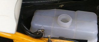
- The fuel level indicator needle “dances” or has fallen dead to the zero position;
- The indicator is constantly on, indicating a critical fuel level, although you have just filled the tank full.
FLS on high and low panels
The differences in the sensors on the injectors and carburetors are minimal. Also, the fuel level sensors on VAZ 2109 cars equipped with a low and high panel are slightly different.
The difference lies in the resistance indicators. These parameters must be known when checking the condition of the sensor resistor.
In this regard, when buying a new fuel level sensor, be sure to ask for a controller for a high or low panel, depending on what kind of car you have. It is also important to note that in the case of injection engines, the sensor is located inside the fuel pump, but it is based on the same operating principle as a carburetor one.
The speedometer sensor does not work: reasons
DSA malfunctions are usually caused by open circuits, damaged or oxidized contacts.
Structurally, the car speed sensor itself is quite reliable (considering the speed sensor, the device circuit is quite simple).
It is also important to consider the fact where the speed sensor is located. The location in the engine compartment at the gearbox does not prevent oil contamination, ingress of technical fluids, water and dirt, etc.
- At the initial stage, it is necessary to check the wiring and contacts for integrity. As for the contacts, it is necessary to clean and lubricate them (Litol type lubricant is suitable);
- The wires to the speed sensor usually break near the plug at the bend, as the wiring frays and the insulation cracks;
- At the same time, it is recommended to check the resistance in the grounding circuit. The norm is 1 Ohm.
If no wiring or contact defects are found or the methods discussed above do not resolve the problem, you need to check the speed sensor for functionality.
What does the fuel level sensor consist of and how does it work?
The fuel level sensor can work properly for a long time. The mechanism itself is not one of the most painful areas of the VAZ-2114, but, like all other devices, sooner or later it fails. Its breakdown is most often due to the fact that the FLS is in unfavorable conditions.
The device body is quite fragile, which often leads to the sensor breaking due to mechanical damage. Among other things, constant temperature changes significantly reduce its service life. The fuel sensor of the VAZ-2114 is especially painful during the frosty season.
The main purpose of the fuel level sensor is to determine the fuel level in the gas tank and transmit the received data to the indicator, which informs the driver.
In a VAZ-2114 car you can most often find a sensor of the BM-150 type. Regardless of the design feature, the operation of each fuel controller is based on a measuring float made of lightweight material. The operating principle of the device is as follows: a unique signal corresponds to a certain amount of gasoline in the tank. The design also includes a lever and a resistor element.
Taken together, all the parts of the device make it possible to measure resistance, which has different indicators depending on the level of gasoline. Using a sliding contact, it is possible to turn on and off a special indicator on the dashboard.
A full tank has a resistance of 20 ohms, an empty tank has a resistance of 300 ohms.
How to check the speed sensor yourself
Among the main ways to check DSA are:
- checking with a voltmeter;
- diagnostics using a control lamp;
Many cars have a sensor whose operation is based on the Hall effect. It is not difficult to check this type of DSA. However, there are other types of speed sensors: reed sensor, as well as inductive speed sensor. The method for testing such sensors is somewhat different.
Checking the speed sensor with a multimeter
The most common type of speed sensor has 3 contacts: pulse, ground and voltage. First of all, you need to determine the presence of grounding and 12V voltage on the contacts.
These contacts are checked with a multimeter, while the “pulse” contact is checked by rotating. Normally, the voltage between the pin and ground should be from 0.5V to 10V.
To check the speed sensor with a voltmeter you will need:
- remove the speed sensor;
- determine the purpose of contacts;
- switch the multimeter to voltmeter mode;
- connect the incoming contact to the output;
- ground the second contact to the engine (can be to the car body);
Then the speed sensor must be rotated, determining the presence or absence of signals in the work cycle. The output voltage of the sensor is also measured. To do this, it is recommended to put a piece of tube on the sensor axis and rotate it at a low speed of up to 5 km/h. The faster the sensor rotates, the higher the voltage on the voltmeter should be.
How to check the speedometer sensor without removing it
If the owner does not know how to remove the speed sensor from the car or intends to do a quick check, you can do without removing the sensor. For such a check you will need:
- raise the car on a jack so that one drive wheel comes off the ground and rotates freely;
- Next, the sensor contacts are connected to a voltmeter. Then you need to rotate the wheel and determine whether voltage appears, and whether there is a change in frequency;
If the voltage is fixed and the frequency changes, the speed sensor is working. In the case when there is no voltage, there is a high probability of failure of this element.
Quick check of the speedometer sensor with a test light
Checking the speed sensor can also be done using a warning light (or so-called control light). As part of such a check:
- The pulse wire is disconnected from the sensor;
- the car is lifted on a jack;
- one wheel is hung out and the ignition is turned on;
- then one control wire is powered to the “+” battery;
- the second wire will be connected to the “signal” connector;
If the light blinks while the wheel is rotating, the speed sensor is working. If the lamp does not blink, it will indicate that the sensor is faulty and requires replacement.
DPKV sensor in the electronic injection distribution system
Since a broken crankshaft position sensor automatically makes further operation of the vehicle impossible, and every driver can replace it, you should know the following information about this device:
- purpose and design;
- varieties and interchangeability;
- installation location and diagnostics;
- DIY replacement method.
Car manufacturers provide a convenient location of the DPKV, a simple design of the sensors and their low cost, which allows you to have this semiconductor device in stock to carry out emergency removal of a failed sensor, install a new device by connecting it to the connector, knowing exactly the location.
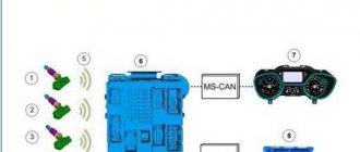
What is it needed for?
In modern diesel and injection cars, the operation of the engine is controlled by an electronic computer unit, which is also called ECU, ECM (module) or ECM (system). For normal operation, electronic systems use sensors and actuators. Signals are received from the sensors, the ECU decrypts and analyzes them, then actuates actuators that inject and ignite the mixture after it is compressed.
The elements of the connecting rod-piston group are hingedly connected to each other, so their amplitudes are easily calculated mathematically. Thus, the ECU computer determines the position of the piston at BDC and TDC using the signals transmitted by the crankshaft position sensor complete with the synchronization disk.
In other words, without a crankshaft sensor, the ECU will “blind”, fuel will be supplied from the injectors ineffectively, and ignition in the combustion chambers will become chaotic, therefore, in a particular car model, the ECU firmware, the type of sensor, the size and formula of the synchronization gear are tightly linked.
How does it work?
Regardless of the sensor design, the operating principle remains the same:
- a disk with teeth, called reference, master or synchronizing, is put on the crankshaft;
- the sensor is mounted on engine elements or brackets in such a way that its working element is perpendicular to the axis of rotation of the shaft, 1 mm from the outer diameter of the ring gear;
- several teeth are ground down through a certain number of complete teeth, depending on the ECU firmware;
- the signal in the DPKV appears precisely at the moment when a section without teeth passes by it;
- therefore, the synchronization disk is installed in a certain spatial position.
In specific motor designs, the reference disk and DPKV can be placed on either side of the crankshaft, but other characteristics of the gear wheel are much more important for the user:
- number of teeth – 24 pcs., 30 pcs., 36 pcs., 48 pcs. or 60 pcs;
- tooth pattern formula - 24/2, 30/3, 36/1 or 36/2, 48/2 and 60/2 are commonly used.
In the simple formulas above, whole teeth are in a row, then 1 or 2 teeth are missing, also in a row.
There are complex formulas, for example, 36/6. Where, after 16 whole teeth, 2 pieces are missing, then 1 whole tooth comes, 2 pieces are missed again, then 13 whole teeth follow, again a gap of 2 pieces follows.
However, the outer diameters of the synchronization disks and their design do not coincide by default.
What modifications are there?
In addition to different options for the synchronizer and its location on the crankshaft, the manufacturer on the conveyor, and later the user himself in the garage or service station, can use DPKV of different designs. There are 3 types of crankshaft sensors:
- Hall - 3 wires come to the chip - +12 V or + 5 V, ground (-) and to supply a signal to the ECU, a power source is required;
- inductive - a connector with 2 contacts is used for connection, since the current is excited in the semiconductor device itself;
- optical - consists of a transmitter with an LED and a receiver that responds to a light beam as the area without teeth passes past it.
The Hall sensor has the following features:
- the current source supplies the windings with a voltage of 5 V or 12 V;
- a magnetic field is created in the coils;
- as long as full teeth pass near the rod, the magnetic circuit remains in the closed position;
- When passing a section without teeth, the circuit opens, and the ECU receives a corresponding signal about this.
The Hall sensor in modern cars can be used in different systems:
- in the crankshaft position sensor mode on some VAZ modifications;
- as a speed sensor on foreign cars;
- in ABS anti-lock wheel systems - each wheel is equipped with a reference disc and its own sensor connected to a common circuit.
The second name for a device that uses the Hall effect is a phase sensor. For example, in camshaft sensor mode, the inductive device is practically useless. Because at low speeds it transmits a weak signal that is difficult for the computer to process.
Inductive DPKV has a simplified design and does not require power supply:
- connection is made with two wires;
- the magnet inside the device creates an alternating field in the core;
- the voltage of the electromotive force increases while passing a section without teeth;
- decreases near full-profile teeth.
The sensor is always operated in DPKV mode and is not suitable for measuring speed.
The optical signal from the DPKV is sent to the ECU controller when a light beam from the LED hits a photocell located on opposite sides of the reference wheel, so sensors installed parallel to the crankshaft are not always convenient to use under the hood of a car.
Optical DPKVs are more expensive and are used on scooters and for diagnostics, calibration of Hall sensors and inductive-type devices.
Where is it located?
Based on the purpose of the DPKV, it is difficult to determine where the sensor is located in the engine structure:
- the middle part of the shaft contains several elbows for fastening parts of the crank mechanism;
- its edges remain free;
- a reference gear with missing teeth is located near the flywheel of the internal combustion engine;
- or the synchronizer is located at the opposite end of the engine power take-off pulley that drives the generator belt;
- less commonly, the drive disk is mounted on the shaft with a key directly next to the counterweight on the flange side.
Since the reference disk does not engage with gears and does not transmit rotation to belts and chain drives, it almost never fails, even during long-term operation. However, there will always be sources of dirt around the machine that can cause gaps where missing teeth become clogged with dirt.
To restore the correct transmission of signals about the position of the pistons on the crankshaft, simply remove the DPKV and clean the area with WD-40 or silicone spray.
What is a DPKV simulator?
Unlike the sensor itself, the DPKV simulator is used to configure the ECU firmware during their manufacture. At the operational stage, the device is necessary to test the correct operation of the pulse transit time according to the calculation table.
How to check the speed sensor drive
In some cases, the cause of the malfunction may also be not the sensor itself, but its drive. For this reason, it is also recommended to check the speedometer sensor drive. For such a check you will need:
- jack up the car and hang out the wheel;
- detect the sensor drive coming out of the gearbox;
- rotate the wheel (you can use your foot yourself or have an assistant);
While the wheel is rotating, you need to tactilely evaluate the quality of the drive (feel it with your fingers). It is important not only to make sure that the drive works, but also how stable its overall operation is.
We also recommend reading the article about the signs of a malfunction of the IAC idle air regulator. In this article you will learn about ways to check the idle speed control.
As a rule, any deviations from the norm are grounds for disassembling the drive. Often the teeth on the speed sensor drive gears are damaged.
What is a coolant temperature sensor
All sensors are used to monitor the operation of certain components and parts. If the operation functions are disrupted, the sensor indicates that the operation of a particular device is unstable. A car has many sensors in its design.
Important recommendation: is it possible to mix antifreeze with antifreeze or with each other, or with water, and what will happen if you mix it? The answer can be found in the link.
The internal combustion engine needs stable operation. So, the cooling fluid temperature sensor provides control over the stability of the internal combustion engine. The car’s engine heats up faster thanks to this sensor and is slower to reach high temperatures that lead to boiling of the coolant in the system.
DTOZH is not a sensor that shows the temperature of the fluid in the block and radiator system. Some people have the wrong idea about this.
If the sensor that displays the temperature value for the driver breaks down, then this will not bring anything serious to the system. And, if the sensor that transmits the temperature value to the computer fails, then the control unit will incorrectly regulate the operation of the internal combustion engine.
Information for novice motorists: the cooling system (radiator, engine cooling system jacket) must contain a liquid (preferably one that has a high boiling point) that removes heat from the engine.
In addition to removing heat and cooling the engine, the circulating coolant cools the engine oil, which, when boiling, loses its properties.
The coolant also cools the air that is in the turbocharging system (turbine), cools the exhaust gases and the gearbox oil. The sensor has the function of heating air in ventilation and heating systems.
The coolant temperature sensor is a small link in the aggregate design of the car system, but it is very important. The stability of the motor depends on its correct operation and serviceability in general.
Other types of speed sensors: reed switch type and induction type sensor
Although such sensors are used much less frequently than Hall effect sensors, such solutions are found on some cars. For this reason, it is necessary to take into account some features.
- A sensor with a reed switch produces signals in the form of rectangular pulses with a cycle of 40-60%, while switching is carried out from 0 to 5V or from 0 to battery voltage 12V.
- As for the induction sensor, the signal from the rotation of the wheels is similar to a wave oscillation (wave impulse). As a result, the voltage changes based on the rotation speed. The principle itself is similar to the operation of the crankshaft angle sensor.
Building an inductive sensor
What does this mechanism consist of? Non-contact inductive sensors have the following main components:
- Generator. Creates an electromagnetic field, which is necessary to interact with an object.
- Schmitt trigger. It provides hysteresis when switching occurs.
- Amplifier. It is engaged in increasing the amplitude of the signal so that it reaches the required value.
- Led indicator. Informs about the status of the switch. It also provides performance monitoring and indicates the efficiency of setup.
- Compound. Necessary to protect against the ingress of water and solid particles.
- Frame. With its help, the sensor is mounted and protected from various mechanical influences. Made from polyamide or brass and supplied with fasteners.
Let's sum it up
The speed sensor (speedometer sensor) is an important element in the electronic engine control system. If the driver notices the signs of engine malfunctions discussed in the article, special attention should be paid to the vehicle speed sensor.
We also recommend reading the article about what a phase sensor is. From this article you will learn about the signs of a faulty phase sensor, as well as how to check it.
In addition to checking other sensors (mass air flow sensor, speed sensor, speed sensor, etc.), it is also necessary to diagnose the speed sensor. The reason is that the failure of one or another sensor will not always be accompanied by the lighting of the “check engine” warning light on the instrument panel. As a result, in-depth diagnostics are required.
ABS system diagnostics
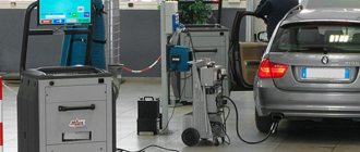
Before you start checking the ABS sensor, you should determine which one is not transmitting a signal. The easiest way to do this is with computer diagnostics.
For cars produced after the 2000s, this is not difficult. clearly determine which of them does not provide information about the state of the rotational movement of the wheel.
But this information does not always indicate a malfunction of the sensor itself. On the contrary, as a rule, the ABS sensor itself is working, and the fault lies in the wiring going to it or the wheel rotation reading device.
What does it affect?
The main task of the coolant temperature sensor is to turn on the cooling fan. As a result, if it malfunctions, the fan does not operate, and this may result in overheating of the motor or, at a minimum, boiling of antifreeze in the aggregate.
Video - how to check DTOZH with a multimeter:
Besides
, on injection engines, a malfunction of the DTOZ leads to the fact that the ECU sets the wrong ignition timing,
the engine increases and
fuel consumption begins to work in negative conditions.
The combination of these factors shows that timely replacement of the sensor and identification of the sensor is the main element that allows you to avoid many troubles, and sometimes expensive repairs of the car engine.