Replacing the ignition switch of a Gazelle car
Page 1 of 2
The ignition switch bracket is secured to the steering column with two bolts, the heads of which are sheared off at a certain tightening torque.
Replacing the contact part of the ignition switch
1. Disconnect the wire from the negative terminal of the battery.
To replace the contact part of the switch, remove the steering column covers (see the article - “Removing and disassembling the steering column”).
2. Using a slotted screwdriver, unscrew the two screws holding the steering column covers together.
3. Remove the top casing.
4. Move the steering column to its highest position.
We tilt the upper edge of the casing toward you until its lock comes out of the column slot.
5. Remove the casing by moving it upward.
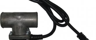
6. Using a slotted screwdriver, unscrew the two screws securing the contact part of the ignition switch.
7. Remove the contact part from the lock body.
Disconnect the connection block of the switch.
R
is. 8
We connect the new switch to the connector, put it in place, aligning the groove in the hole with the protrusion on the lock, and fasten it with screws.
Gazelle Business Ignition
Removing the ignition switch. Gazelle business!
In the forest, while picking mushrooms, I lost my keys (they flew out of my pocket, okay, at least the car wasn’t locked at the alarm. laugh.gif ).
And so on in order.
Don’t break the lock, (if you have a spare key) it’s a very expensive pleasure to have a new lock, we have 2300 rubles + two locks for it on the body.
In general, it took me 15 minutes to remove the lock while traveling.
We unscrew the bottom plastic cover of the lock, two bolts, and 4 self-tapping screws. Remove it.
Now we unscrew the two countersunk bolts, they unscrew easily, I had an ordinary screwdriver and a hammer, we put the screwdriver like a chisel into the edge of the countersunk one, and hit it with a hammer, and it slowly unscrews, it took me five minutes to unscrew these two countersunk ones (now I installed the usual ones, with edges, I don’t see the point in installing hidden ones, because with edges it seemed to me that I took longer to tighten, it’s more difficult to get there with a key)
More photos.
Lock number.
Now the main thing is that without the lock itself, the console of switches, turn signals and wipers will not be held in place; the lock is a clamp to the steering shaft. In order for this console to be in place, I put the lock in place, and so that it does not lock the steering shaft, I placed a thick cardboard that prevented the lock from flying out and jamming the shaft.
Advertisements!
Advertisements for advertising purposes from Vasilich:
“For sale is XprogM - not made in China, a completely redesigned baseboard, plus 14 adapters. Version 5.45 - 5.51 ALL are open. authorization (including MAC, Infinion, CAS4) Unlike China, there are NO glitches. I checked it personally. You can buy it here. I will also update Chinese XProg there.
There is always an iProg USB and motorola adapter on sale that supports a large number of motorolas, as well as NEC and TMS, you can buy it here
Attention to all iProg USB owners. I'm starting to update the summer 2014 tracing paper and motorcycle adapters, read the details here. For owners of motorcycle adapters, we run NEC VDO via 4 wires, see here
For owners of motorcycle adapters, we run NEC VDO via 4 wires, see here.
On sale there is a CAN-BLOCKER for winding up mileages on a Mercedes, with locks on a NEC processor, more details here
Gazelle business scheme
The electrical wiring of the Gazelle business consists of four harnesses: front, rear, instrument panel harness and engine control system harness. All harnesses are connected to the front wiring harness using connectors. The connection between the engine wiring harness and the front wiring harness is the same regardless of engine type or trim level. If we compare the Gazelle business scheme with the schemes of previous models, we will not see any big changes. Although it’s worth dwelling on this a little.
style=”display:inline-block;width:728px;height:90px”
data-ad-client=”ca-pub-3349146820748021″
data-ad-slot=”9290054688″>
The first difference will make it much easier to replace the wiring or part of it. The fact is that in previous models, the front harness and the instrument panel harness were connected to each other not only by connecting connectors, but also on fuse blocks. Gazelle business harnesses are connected only using connectors. The next difference is a slightly more complicated heater switching circuit. This is due to the use of an electronic control unit and a variety of gear motors for remote control of the dampers and heater tap. There is also a slight difference in the connection diagram for external lighting and headlights. Another significant difference is the presence of a relay and fuse box. The diagnostic connector is also located in the same block.
There are also minor changes in the arrangement of circuit elements on the car. We have already mentioned the relay and fuse box, which now houses all the relays, and is not mounted under the steering column as on previous models. The windshield wiper relay is also located there, which was previously located on the left wing in the engine compartment. The turn and hazard warning relay is now located on the steering column under the top cover. The hazard warning button is also embedded there. Other changes are related to the location of the controls and are perhaps not worth dwelling on.
The Gazelle business engine diagram depends on the installed engine. Most often they are equipped with a UMZ 4216 gasoline engine with a Mikas-10.3 (11.3) ECU. The CUMMINS ISF2.8 diesel engine is also installed as standard. On request, ZMZ 405 engines with Mikas-11 (12) ECU can be installed.
Below are links to wiring diagrams and some calculations. You can also download the Gazelle business scheme from a file hosting service here.
How to replace the ignition switch of a Gazelle car
Page 1 of 2
The ignition switch bracket is secured to the steering column with two bolts, the heads of which are sheared off at a certain tightening torque.
Replacing the contact part of the ignition switch
1. Disconnect the wire from the negative terminal of the battery.
To replace the contact part of the switch, remove the steering column covers (see Removing and disassembling the steering column).
2. Using a slotted screwdriver, unscrew the two screws holding the steering column covers together.
3. Remove the top casing.
4. Move the steering column to its highest position.
We tilt the upper edge of the casing toward you until its lock comes out of the column slot.
5. Remove the casing by moving it upward.
6. Using a slotted screwdriver, unscrew the two screws securing the contact part of the ignition switch.
7. Remove the contact part from the lock body.
| Disconnect the connection block of the switch. | We connect the new switch to the connector, put it in place, aligning the groove in the hole with the protrusion on the lock, and fasten it with screws. |
Replacing the ignition switch of a Gazelle car
Page 2 of 2
1. Remove the steering column cover.
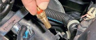
2. Disconnect the ignition switch wiring harness block.
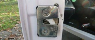
3. At the bottom of the ignition switch, unscrew the screw securing it to the bracket
4. On top of the switch, use a thin screwdriver to press the pin into the bracket body
5. Remove the switch from the bracket
6. Remove the two screws securing the contact group to the switch
7. Disconnect the contact group from the switch
If the new contact group does not have a wiring harness, unsolder the wires from the terminals,
having previously marked their position in any way.
It is necessary to mark it, because two wires are blue, and there are no pin markings on the contact block.
8.
Solder the wires as shown in the figure.
Install the parts in reverse order.
Removing the ignition switch assembly
To remove the ignition switch assembly, it is advisable to remove the steering column (see Removing and disassembling the steering column) and unscrew two special bolts.
1. If their heads are not broken off, then unscrew them with a “10” key.
2. Otherwise, remove the contact part of the ignition switch,
To avoid splitting it during operation, use a thin chisel to loosen the bolts.
3. Use pliers to unscrew the bolts.
4. Remove the lock.
For subsequent assembly we use new special bolts. To protect against theft, their hex heads can be broken off.
How to determine the malfunction?
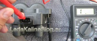
If malfunctions occur in the operation of the equipment, first of all you need to check the integrity of the safety devices. If a short circuit or voltage surge occurs in a wiring circuit, the safety elements are the first to fail, protecting the major devices and electrical equipment connected to a particular circuit. Since a visual check is not always effective, troubleshooting should be done using a tester - a multimeter.
The diagnostic procedure consists of removing the fuses from their seats and further checking the sockets. If you have identified a failed fuse, this does not mean that the test can be completed, since a short circuit can occur simultaneously in several circuits (video author - Denis Legostaev).
If a short circuit occurs in the wiring of a car with a carburetor or injection engine, then you need to diagnose the condition of the circuits. Of course, if all the fuses were intact. Before diagnosing, you should disconnect the mass; directly for checking you will need a tester or test light. When using a lamp, one of its contacts should be connected to the base and the other to the center contact.
The check itself goes like this:
Another important point is diagnosing the integrity of electrical circuits. In this case, the search principle is quite simple - for diagnostics you will need the same tester (a voltmeter or ohmmeter will do) or a lamp with wires. You will need to connect one of the probe contacts to the vehicle body, and use the second contact to measure the power at the connecting points between yourself and the equipment.
It is best to start in the middle of the circuit and check easily accessible areas first. In addition, to diagnose a break, it should be understood that most often circuit damage occurs in places where the wiring is bent. Moreover, as practice shows, wire harnesses are very rarely damaged.
Another breakdown in the electrical circuit is poor contact at the connections; searching for such a fault is best done using a tester - a voltmeter.
There are two diagnostic methods:
- One probe of the tester should be connected to the car body, and the second to the connection terminal; voltage measurement is carried out in both directions. Please note that the voltage drop should be no more than 0.5 volts.
- The next method is to connect one wire to the contact on one end of the plug, and the second to the contact on the other side of this plug. If the tester shows more than 0.5 volts, this indicates that the contacts on the plug should be cleaned (the author of the video is the MZS TV channel).
Removing the cylinder from the ignition switch
Disconnect the plugs in advance.
1) Undress the steering wheel, remove the upper and lower plastic. The lower one is difficult to remove; to do this, you need to bend the steering wheel adjustment knob (first unscrew 2 screws with a skate screwdriver).
2) It is impossible to remove the clamp, since the factory nuts do not have edges. You will have to cut it with a grinder, the main thing is to stop in time, otherwise you can cut the main steering column pipe.
3) After cutting, a small piece should fall off, either by itself or with a couple of blows with a hammer.
4) For convenience, you can unscrew the steering column itself. This is a long bolt that goes to the steering wheel height adjuster. It is secured with 2 12mm nuts on the left and a 12mm bolt head on the right. To remove this bolt without any extra effort, you need to raise the steering wheel as high as possible. When removing a bolt, you need to remember the position of the brace (at the bolt head). Then you need to stick it in as well.
5) The steering wheel and steering column have fallen, now you can pull out and throw away the old ignition.
6) Take a new bracket and make slits in the sides where the heads of the tightening bolts will be. These slots are needed so that later you can tighten the 4 tightening bolts with a ratchet without any problems. If you do not make the slots, the head on the ratchet will rest against the edges, and the ignition will not be able to be tightened properly.
7) Place the left part on the steering wheel, attach the right one, then unscrew 4 bolts and tighten them as much as possible. Tie the steering wheel with a long bolt, without tightening the 2 nuts too much, this will prevent you from adjusting the steering wheel.
 Hang the plastic, connect the plugs, try to start it.
Lock replacement and repair
If, when you try to turn on the key, nothing happens in the lock, that is, the engine does not start, the problem may lie in a poor connection of the contacts. You can try to repair such a lock, but if this does not help, then the device will have to be changed (the author of the video is Sergey Vishnyakov).
Replacement of the contact group
This task is performed as follows:
- First you need to disconnect the battery, to do this, remove the negative terminal from it. Next, the protective lining of the steering column is dismantled. Using a flat head screwdriver, you will need to remove the two bolts that secure this shroud.
- Having done this, you can dismantle the upper part of the lining.
- Next, the steering column is moved to its highest position. You will need to slightly tilt the top of the cover towards you until the fastenings of this part of the casing come out of the slot.
- Then the lining is dismantled; it must be moved upward.
- Using a flat-head screwdriver, you will need to unscrew the two bolts that secure the contact part of the lock. Then the contact component is removed and replaced with a new one, further assembly is carried out in the reverse order.
Photo gallery “Changing the contact group”
Changing the lock
To completely change the lock, do the following:
- As in the previous case, you first need to remove the protective casing.
- It will not be possible to dismantle the clamp, since the standard nuts do not have edges, so it must be cut, for example, with a grinder. Be careful not to damage the steering column tube.
- Next, you will need to disable the steering column - this is done to make the further replacement procedure more convenient. First, the long screw connected to the steering wheel height adjuster is unscrewed. After this, the steering wheel itself should be lifted up, this will allow you to unscrew another bolt; for this, use a 12-mm wrench. When removing the screw, you will need to remember the position of the brace; it is located next to its head.
- The next step will be to remove the old ignition.
- Now take the new bracket and make slits in the sides where the lag screw heads will be located. The slots are a must because they will allow you to easily tighten the four lag screws. If the slots are missing, this will lead to the heads on the ratchet resting on the edges, so it will not be possible to securely fix the device.
- Next, the device is placed in the seat, four screws are tightened, they need to be tightened to the maximum. The two 12mm nuts that you unscrewed earlier do not need to be fully tightened, as this will result in you not being able to adjust the position of the steering wheel. Assemble the entire structure and test the operation of the installed lock.
Recommendations based on your search history
REPAIR OF IGNITION SWITCH VAZ 2115 – Duration: 11:51
- 3 years ago
- 156
Anyone who has problems turning on the starter should watch. Useful advice from an auto electrician. – Duration: 14:11
- 1 year ago
- 1 020
SOLVING THE PROBLEM WITH THE IGNITION SWITCH VAZ 2110 2111 2112 – Duration: 7:48
- 1 year ago
- 96
All power to the car is lost. stalls, won't start, nothing works - Duration: 6:10
- 4 years ago
- 499
The ignition does not turn on. The tension is gone. – Duration: 16:45
- 3 years ago
- 441
The starter does not turn, should we change the lock or not? Useful advice from an auto electrician. – Duration: 9:59
- 2 years ago
- 593
Open a gazelle without a key – Duration: 2:42
- 2 years ago
- 64
Removing and disassembling the ignition switch. Repair of the lock cylinder on an Opel Vectra B. – Duration: 7:56
- 4 years ago
- 221
Removing and repairing the ignition switch - Duration: 8:53
- 5 years ago
- 121,541 views
GAZELLE. The starter does not turn, we are looking for the reason. – Duration: 4:27
- 4 years ago
- 91
Egnition lock. Is it possible to understand its electrical part? – Duration: 29:09
- 3 years ago
- 124
Connecting the Ignition Lock (GAZelle) – Duration: 3:47
- 4 years ago
- 33,552 views
Replacing the ignition switch on a gazelle/Power failure will not start. – Duration: 9:41
- 3 weeks ago
- 74 views
Ignition switch gazelle – Duration: 3:06
- 3 month ago
Starting a Gazelle with a faulty ignition switch – Duration: 3:20
- 1 year ago
- 4,781 views
Replacing the ignition lock cylinder – Duration: 12:35
- 2 years ago
- 151
In this video I talk about how to replace the Matiz ignition lock cylinder.
We accept donations for development.
Replacing the lock cylinder on the Next gazelle – Duration: 7:47
- 12 months ago
- 9,871 views
Ignition switch contact group: device and replacement - Duration: 12:11
- 2 years ago
- 133
Ignition switch contact group - device and replacement in a visual video.
Replacing wiring
Advice: replacing functional control devices on the panel due to new connectors is not justified.
Therefore, when integrating new wiring, the connection diagram in the connecting terminals only changes, and for alignment you should use the wiring diagram of the new power unit.
Changing everything to 406 is certainly not impractical.
The fact is that on newer versions of Gazelles, the connection diagram of certain devices also changed:
- Gazelle 406 wiring is integrated into the standard electrical system in the engine compartment;
- electronic components and control devices are connected using terminals;
- The voltage and correct connection are checked using testers.
After assembling the wiring into a single whole, its functionality is checked. Subsequently, the operation of the power unit is adjusted.
Conclusions: Replacing a power unit inevitably involves changing the standard electrical wiring of the car. That is why it is important to have a visual aid at hand when carrying out such an operation, and the factory one will allow you to avoid mistakes.
Today, Gazelle cars are used in many sectors of modern business. To ensure the operability of the vehicle, it is necessary to pay attention not only to the performance of the main components and assemblies, but also. From this material you will learn everything you need to know about the operation of wiring and its malfunctions.
[Hide]
Replacing the ignition switch gazelle 3302
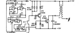
Electrical diagram of a Gazelle car
Electrical diagram of Gazelle cars with UMZ-4216, ZMZ-40522 engines : 1- left side turn signal; 2 – left headlight; 3 – right headlight; 4 – right side turn signal; 5 – starter; 6 – fuse box (in the engine compartment); 7 – headlight relay; 8 – central lighting switch; 9, 10 – lampshades for cargo compartment lighting (for vans); 11 – canopy lighting for the front part of the cabin; 12 – windshield washer motor; 13 – courtesy lamp for the rear part of the cabin (for vehicles with two rows of seats); 14 – switch for the interior lighting of the rear part of the cabin (for vehicles with two rows of seats); 15 – platform lamp (GAZ-3302, -33021, -33027); 16 – buzzer switch (GAZ-3302, -33021, -33027); 17 – driver signal buzzer (GAZ-3302, -33021, -33027); 18 – sound signals; 19 – sound signal relay; 20 – ignition switch; 21 – starter relay; 22 – generator; 23 – battery; 24 – battery switch; 25 – button for remote battery switch; 26 – electric drive of the heater valve; 27 – electric pump for additional heater; 28 – heater electric fan resistor; 29 – heater fan electric motor; 30 – heating and ventilation control panel (1 – heater tap switch; 2 – heating and ventilation control panel backlight lamp; 3 – relay; 4 – main heater electric fan switch; 5 – auxiliary heater electric fan and electric pump switch); 31 – upper fuse box (in the cabin); 32 – lower fuse block (in the cabin); 33 – engine compartment lamp; 34 – hazard warning light switch; 35 – radio receiver; 36 – resistor of the additional heater electric motor; 37 – additional heater electric motor; 38 – interior lamp switch (right side); 39 – interior lamp switch (left side); 40 – lamp for lighting the steps (for buses); 41 – interior lamps (right side); 42 – interior lamp (left side); 43 – cigarette lighter; 44 – switch for checking the serviceability of signaling devices; 45 – sensor for emergency drop in brake fluid level; 46 – right steering column switch (switch for direction indicators and headlights); 47 – direction indicator relay; 48 – switch for electric headlight correctors; 49 – parking brake warning switch; 50 – parking brake warning relay; 51 – lighting control of the instrument cluster; 52 – connector (wire block) for connecting the ABS system; 53 – instrument cluster; 54 – brake signal switch; 55 – switch for the glove compartment lamp; 56 – lampshade lighting of the glove box; 57 – fuel module; 58 – center differential lock warning switch (for 4×4 vehicles); 59 – windshield wiper control relay; 60 – engine control system blocks; 61 – coolant temperature indicator sensor; 62 – coolant overheat indicator sensor; 63 – windshield wiper; 64 – oil pressure indicator sensor; 65 – emergency oil pressure indicator sensor; 66 – right steering column switch (horn and windshield wiper switch); 67 – speed sensor; 68 – reverse light switch; 69 – rear light (right); 70 – license plate lights; 71 – rear light (left)
Functions of vehicle electrical systems
Wiring diagram for Gazelle 405 with an engine of the ZMZ family.
In any modern car, electrical wiring serves to transmit signals to actuators and electronic components. Accordingly, depending on the functionality of the vehicle and its technical features, electrical wiring has its own unique features.
For example, the wiring diagram for a Gazelle of different modifications is different due to the different arrangement of certain electronic components in the car caused by the use of different systems:
- Carburetor versions of the power unit provide their own independent ignition system;
- In injection versions of engines, the ignition system functions in conjunction with the fuel injection system.
Injection engine ZMZ-405.22
Types of power units
The Gorky Automobile Plant, which mastered the production of Gazelle cars, which it first introduced to the automobile market in 1994, initially had two suppliers of power units:
- The Ulyanovsk Motor Plant supplied power units of the UMZ family (carburetor);
- Zavolzhsky Motor Plant, which supplied the ZMZ family of carburetor and injection engines.
This is a feature of the domestic automobile industry, which consisted in unifying the line of gasoline power units for the Gazelle with Volga passenger cars produced by the GAZ plant and UAZ SUVs of the Ulyanovsk Automobile Plant throughout the entire period of their production, but the wiring diagram was redesigned for the truck version.
Cars with such engines received their own names among motorists - Gazelle 421 (from the UMZ-4216 engine), Gazelle 405 (from the ZMZ-40522.10 and 40524 family of engines) and others.
Accordingly, different engine control systems required a different electrical wiring system:
- Injection power units, being more demanding on the combustible mixture ignition system, are equipped with electronic ignition components and a fuel injection control system, the performance of which depends on the quality of the fuel;
- Carburetor versions of the engine are more traditional, but have their own design features; accordingly, the electrical wiring of the gazelle in the engine compartment is made somewhat differently.
In 2001, a diesel version of the engine from the Gorky Automobile Plant (GAZ) family appeared in the list of modifications, which began to be offered for the vehicle.
Such a Gazelle also required electrical wiring with modified characteristics (more powerful starter, generator and battery).
Environmental requirements
Having started production of the Gazelle car, the automaker used existing wiring diagrams, in particular the ZMZ 402 engine, which was equipped with Volga family cars. Naturally, there was no talk of compliance with environmental standards in those years.
The Euro 2 environmental standard, which appeared in Western European countries in 1995, and regulates the content of harmful substances in exhaust gases, gradually forced domestic automakers to modify the configuration of power units:
- Modernization of existing internal combustion engines by installing electronic fuel injection (injection system);
- The release of multi-valve engines (16 instead of 8) made it possible to equip the power unit with a more modern electronic ignition and power system.
Modifications of power units for Gazelle and their compliance with environmental standards for all years of production
Additional measures taken at the legislative level in the form of the introduction of certification requirements contributed to the emergence of new power units for the Gazelle family that meet Euro-3 standards. Since 2008 they have become:
- ZMZ-40524.10;
- UMZ-4216.
Accordingly, the wiring for the Gazelle 405 engine, whose engine complied with Euro-3 standards, as well as the 421 engine, was thoroughly redesigned taking into account the increased functionality and technical features of the power units.
Gazelle Ignition Switch
Ignition switch
We are changing the ignition switch. I decided to change it because... It often happened that the key slipped, and already, the engine was running, but the starter was still spinning. You would start Plus, but the heater didn’t work, the low one didn’t light up (the key had to be moved here and there) I CHANGED IT IN 25, MINUTES ALREADY THE SECOND REPLACEMENT, the first was the first on the car, there I changed the hour. The best thing I bought a cheap one, I didn’t take Nizhny Novgorod for RUB 800. and it works fine (on an old, proven machine) Now I already know how to come up with something, modify it. I’ll explain in detail, because If people are faced with a replacement for the first time, then it will be incomprehensible to them anyway. If it’s problematic, read and also change it in 25 minutes))))) Disconnect the plug in advance.
1. Undress the steering wheel, remove the top and bottom plastic, the bottom one is problematic to remove, to do this, bend the steering wheel adjustment knob (first of course, unscrew the 2 screws of the ridge strip). Using a screwdriver:
2. It’s impossible to remove the clamp, the factory ones have no edge nuts, we cut them with a grinder mercilessly, the main thing is to stop in time, otherwise you’ll cut the main column steering pipe.
3.Cut a small piece and it should, well, fall off a couple of times with a hammer.
4. For further convenience, I unscrewed the steering column itself. This is the long bolt that goes to the steering wheel height adjuster. It was unscrewed, on the left 2 on the right by 12, the nuts on the bolt head by 12. To remove this bolt, without any extra effort. Raise the steering wheel as much as possible. up. When you take it out, look at the bolt and remember the position of the brace (the head of the bolt). And then stick it in as well.
5. The steering wheel and steering column have fallen. We take out the old one. Give the ignition to his neighbor or mother-in-law (in the old ones with the keys included).
6. We take a new bracket and make slots in the sidewalls where the heads of the tightening bolts will be. And these slots are so that you can then easily tighten the 4 tightening bolts with a ratchet; if you don’t make the slots, the head will rest against the edge of the ratchet, and you won’t tighten the ignition suddenly. Yes, and maybe again you’ll have to remove the ignition yourself.
7. It’s just a matter of small things: we put the part on the left handlebar, attach the right one, screw in 4 and tighten the bolts to the maximum. We tie the steering wheel with a bolt tightly, don’t tighten the long 2 hooks, otherwise you can then adjust the position of the steering wheel to suit you.
8. assembled everything, hang up the plastic, connect the plugs, try starting it. AND A MEGA IMPORTANT STEP)))))
9.”Wash” the ignition)))))
Good luck on the roads, I’m waiting for comments from Ivanich)))))
#1 questions?
Man 02 January 2012 – 20:25
GAZ 31 Transitional › Logbook › 02.19.15. Replacing the door lock cylinder.
Good evening! I’ve been making frequent recordings, maybe I’m already tired of it? Well, since you came here, read and look at the pictures. )))
Today I went to the garage to try on yesterday's new clothes. I grab the BC... and in response there was silence, I didn’t even blink (((I started scratching my turnip, something was wrong. This shouldn’t happen. I remembered that before that, my self-diagnosis (with a jumper) didn’t work either, which means something is missing For the BC to work, 3 contacts from the diagnostic block are needed: “2” - +12V, “11” - K-Line and “12” - ground. Judging by the diagram
+12V is constant and is taken from the ECM relay, and since the engine is running, that means there is “+”. All that remains is to check the ground and the K-line. I'm 95% sure that the problem is Massa, because... if there were no K-line, then the BC should have blinked anyway. And as luck would have it, there was neither a multimeter, nor a tester, nor a piece of long wire to tie to the light bulb. Therefore, I left the chain testing for later. I now have just 5 days off))): February 19 Local New Year - Sagaalgan, working day February 20 - moved to 28.02. well, February 21,22,23 like in the rest of Russia)). So I think there will be enough time.
I sat and scratched my turnip... Well, okay, one thing didn’t work out, so there are plenty of them and others. There will be enough spare parts purchased new and not supplied for another month)). I decided to take care of the essentials. I have been worried about the issue of locking and unlocking doors for a long time. I only have one key, and it’s pretty worn and regularly jams. Sometimes you stand at the door for half a minute or a minute, turning it back and forth until it gets into the right position. In general, I took out a set of larvae from 3102 from the package with spare parts and started replacing. I think almost all Volgovodians know how to change larvae, but for those who don’t know, look at the pictures. I removed the door card, and for some reason I unscrewed the “loaf” O_o. Loosen this screw here
I pulled out the larva, and we heard that something fell inside the door. We climb into the door, feel for this “something,” take it in our hands, and together with the larva we go into the light. This “something” turned out to be a retainer.
We pull out the cotter pin from the larva, disassemble it into parts, and lay it out. You should get 4 parts: the body of the larva, the larva itself, the pin and the cotter pin.
We take a new face and compare it with the old one. Once again we note how shitty the quality of spare parts is now. They are even different in height and casting defects are not removed.
We close our eyes and put this g...but into the body of the larva. We check that the protrusions on the body are facing up, and the key inserted into the cylinder is facing down with its teeth.
We combine the holes in the cylinder and the pin, put the cotter pin in place
Now the most difficult part: We insert the cylinder into the door, put on the latch and “by touch” insert the pin into the door latch hole.
Now you need at least three hands, or two very flexible ones. We hold the cylinder with one hand, with the second hand we set the lock in the correct position, with the third hand we turn the screw (which was loosened at the very beginning). We insert the key and check whether everything works correctly.
We take out the key, spray a little WD40 into the cylinder (NOT ADVERTISING, other liquid lubricants can be used)