Design
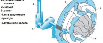
The compressor device has a rather complex, but at the same time very understandable design. It includes elements such as:
- Frame. It is made mainly from materials that can withstand high temperatures. Typically, this material is steel. The body is made in the shape of a snail, which has two differently directed pipes.
- Turbine wheel. Promotes the conversion of exhaust gas energy into shaft rotation energy. Attaches directly to the shaft. An iron-nickel alloy is used to make the wheel.
- Compressor wheel. Promotes the injection of air into the cylinders, obtained from exhaust gases scrolled through the turbine wheel. The material used to make this part is aluminum. The advantage of choosing aluminum is the reduction in energy losses.
- Turbine shaft. The element is designed to connect the turbine and compressor wheels.
- Bearings. They are also sometimes called ball bearings due to the fact that they provide articulated mounting of the shaft in the housing. The design may contain from one to two bearings.
- Bypass valve. Responsible for the amount of incoming gas, redirecting it and thus acting on the turbine wheel. The valve is additionally equipped with a pneumatic drive.
The simultaneous operation of all elements makes the engine efficient.
Boost boost controllers (solenoids)
In front of the activator there is a special device called a solenoid, it is capable of changing the pressure that is supplied to the activator, as a result the solenoid “deceives” the activator by giving out not the pressure that actually exists, but the one reported by the solenoid. Therefore, if the pressure before the solenoid is 13 psi, then after the solenoid it is 10 psi, as a result the bypass valve , which is ready to be activated already at a pressure of 12 psi, will be inactive until 15 psi. This will open the bypass valve at a pressure of at least 12 psi, and the actual pressure will be
The solenoid operates by using the duty cycle of a small mechanism. When the operating cycle changes, it becomes possible to control the air flow through the solenoid. The control is carried out by a computer that analyzes the pressure and, guided by certain algorithms, makes a decision to increase or decrease the boost by opening or closing the bypass valve.
Principle of operation
The operation of the compressor is based on the elements performing the following stages:
- The turbine wheel blades receive the exhaust gases.
- The wheel begins to rotate, gradually increasing the speed of rotation. If necessary, the wheel can accelerate to 250,000 rpm.
- The accelerated gases pass through the turbine wheel to the start valve.
- The compressed air enters the compression wheel, which redirects it with a uniform movement into the intake port inside the engine cylinder.
With the help of the above actions, the engine begins to work actively, forcing the car to move away.
Peculiarities of turbine operation
If we compare the action of a turbocharger with a standard air supercharger, which operates solely from the crankshaft drive, the main advantages of the first will be:
- reuse of exhaust gas energy;
- low price;
- energy saving.
The design of the compressor turbine is almost the same when used on diesel and gasoline engines. However, preference is still given to compressors for diesel units.
The peculiarity of a turbocharger lies in its mode of operation. For gasoline engines, the devices are made of heat-resistant materials due to the high temperature of the exhaust gases, which can reach 1000°. A diesel engine has a lower gas temperature, which is why the materials used in the turbocharger are less heat-resistant.
How is the bypass valve draft adjusted?
The lever has its own mount on which it moves freely. If this is not the case and movement is limited or difficult, there is a problem that needs to be corrected. It happens that the movement of the lever is intermittent, this is especially noticeable when heating. The activator rod can have different lengths, this allows you to adjust the degree of opening and closing of the bypass valve. If it is necessary to shorten the bypass valve rod, the end is tightened; if it is necessary to perform the opposite action, everything happens exactly the opposite. The shorter the pull, the tighter the valve will be closed, while the activator will require much more pressure to open the valve. The higher the pressure, the more the turbine will spin, and the bypass valve, in turn, will not be able to open as quickly.
If you use a feedback controller that can independently measure and control, adjusting the bypass valve draft will not achieve the same result that can be obtained without feedback. The reason is that the controller “takes into account” the changes that have occurred, therefore, such an adjustment will not give a significant result. In addition, a good electronic controller is capable of keeping the bypass valve closed at an activator pressure of 0 psi until the required pressure is reached, resulting in a much faster increase in pressure.
An external bypass valve is a separate device designed to operate outside the turbine, that is, in a separate housing. These types of bypass valves are most often used for higher air flow. As a rule, they have a double activator, which allows the valve to open much faster, thereby providing better control over the state of turbine spin-up.
Additional system elements
There are a few additional elements worth considering separately. They are also included in the design of compressors and regulate certain processes.
Blow-off valve
A blow-off valve is also called a bypass valve. This valve is installed in the air system, usually between the diesel damper and the compressor outlet. The purpose of the valve is to eliminate emergency situations during operation of the unit. For example, during operation, the unit may go into an unwanted surge mode if this is not stopped in time.
This mode occurs due to high air flow speed. In this case, the compressor tries to close the throttle and wants to do it as sharply as possible. The occurrence of the regime is explained by the fact that the speed of the air flow due to the release of gases and the air flow itself begin to decrease sharply. The turbine, due to the force of inertia, continues to rotate rapidly.
If you do not reduce rotation, the consequences can be dire. One of the signs of such an air surge is an unpleasant sound that breaks through the compressor. Further ignoring the problem will lead to damage to the turbine bearings, which are forced to accept heavy loads due to the surges that occur.
The blow-off valve monitors the pressure inside the manifold and comes into operation if it begins to jump too much. The valve's functionality is ensured by a spring installed inside, with the help of which it is possible to prevent changes in the throttle position and improve the operation of the compressor.
If the valve does not have time and the throttle closes, then the blow-off begins to release excess pressure into the atmosphere. Thanks to such work, it is possible to reduce the risk of an accident and protect the turbocharger from heavy loads that can cause its failure.
Wastegate valve
The mechanical Wastegate valve is installed on the turbine or exhaust manifold structure. The main task of this part is to regulate the level of pressure, which gradually increases inside the compressor.
The designs of some diesel engines do not contain a wastegate, but in the case of gasoline units, the presence of such a valve is a mandatory requirement for its reliable operation.
Thanks to the operation of the wastegate, it is possible to ensure a problem-free and unimpeded exit for exhaust gases from the system. In this case, the exhaust gases bypass the operating turbine. With the help of such a distribution of gases, the required amount of energy is controlled.
Such forethought allows for effective control of the boost pressure inside the compressor. Control is ensured by a built-in spring that creates back pressure. It is this design that controls the bypass flow of exhaust gases.
The valve can be:
- Built-in. The design implies the presence of a damper, which is built into the housing. Housing is also called the “snail” of the main turbine of the unit. This element also contains a pneumatic actuator.
- External. This type of gate is a standard valve installed on the exhaust manifold. This valve has an advantage that makes it more popular than the built-in one. If necessary, the valve allows the bypass flow to be returned. In the case of sports cars, the vent valve vents gases directly into the atmosphere, preventing them from entering the turbine.
Both additional elements contribute to the smooth operation of the automobile turbocharger and prevent the occurrence of unpleasant situations that can lead to various accidents.
Steam turbine control valve
The control valve is designed for a steam turbine. The damper contains a rotary disk installed in the housing on a shaft and bushings. A drive with servomotors connected to the high and low pressure oil lines is mounted on the housing. The servomotor rods are connected to each other by a lever. What is new is that the ends of the bushings are made in the form of truncated cones and two counter cone-shaped bores are made diametrically opposite in the disk. During assembly, the ends of the bushings fit into the disc bores with a gap. It is most optimal to make the landing diameter of the bushings within 0.7...0.8 of the diameter of the damper body. For small shaft deflections, it is advisable to use a material based on graphite reinforced with carbon fiber as an oil seal packing. When the spool moves up (down) from the “middle” position (and then returns it to its original position), the servomotors rotate the disk clockwise (counterclockwise), respectively increasing (decreasing) the steam supply to the steam consumer. This design of the damper makes it possible to increase its reliability. 4 ill.
The invention relates to the field of steam distribution of steam turbines, mainly to low-power turbines operating with high volumetric flow rates of steam of average parameters.
The steam distribution of steam turbines is known. It is known, for example, that turbine steam distribution is made in the form of a rotary control valve [1]. An analogue control damper contains a steam housing, a rotary disk and a drive shaft on which the disk is mounted in a bore of the damper body. The disadvantages of the analogue include the fact that it does not have a drive shaft drive and the issue of sealing the drive shaft, which must be brought out through the bearing out of the damper vapor space, has not been resolved.
The closest prototype of the present invention is the control valve of a steam turbine [2].
The prototype valve contains a housing, a rotary disk with a shaft mounted in the housing on sliding bearings, and a drive with two hydraulic servomotors connected to a high-pressure oil source and to a drain. The servomotor rods are connected to each other by a lever attached to the end of the shaft (trunnion), which is removed through a bearing from the damper vapor space. The trunnion, lever and rods are located in a closed chamber filled with turbine oil and connected to the damper steam space. Due to this, the oil pressure in the closed chamber is equal to the steam pressure in the vapor space of the damper body. The journal is sealed with a stuffing box. The steam pressure before the stuffing box is equal to the oil pressure after the stuffing box, and there is no steam leakage, which is an advantage of the prototype. The disadvantage of the prototype is that in some modes, oil from a closed chamber enters the vapor space of the damper, or steam from the vapor space of the damper flows through the stuffing box into the closed chamber. Thus, in the event of an emergency shutdown of the steam supply to the damper, oil from the closed chamber penetrates into the damper. In the event of an emergency shutdown of the high-pressure oil source, steam leaks through the stuffing box. In the first case, the quality of the steam deteriorates, in the second case, the quality of the oil. In this case, salts enter the bearing and stuffing box, which reduces the reliability of the damper operation. If in the prototype the stuffing box is compressed so tightly that it can withstand the full pressure difference of steam and oil in all emergency modes, then, taking into account the increased friction forces in the sliding bearings, it will create a large friction moment of the axle. In addition, since sliding bearings practically do not allow (due to small clearances between the bearing and the shaft) the axes to break, when the shaft bends under the influence of large steam forces on the rotary disk, the shaft “bites” in the damper bearings, which further increases the friction moment of the damper and reduces its reliability. The disadvantage of the prototype is also the presence of a closed chamber filled with oil, which complicates the valve and its maintenance. The prototype damper is designed for steam turbines operating on low-potential, mainly geothermal steam (steam pressure up to 0.8-1.0 MPa, temperature up to 180-200°C). It is not possible to use the prototype damper as a steam distribution for steam turbines operating on a pair of higher parameters (for example, on a spent pair of upstream turbines) due to its inoperability. This is explained by the fact that at relatively high steam pressures, too much steam forces act on the rotary damper disk, and the bearings are located outside the steam space of the housing and are located at a considerable distance from each other. As a result, the drive shaft receives a significant deflection and the bearings bite.
The purpose of the invention is to create a damper for a control steam turbine that does not have the noted disadvantages of the prototype. The purpose of the invention is achieved by the fact that the valve contains a housing, bushings with sleeve bearings, a rotary disk with axles installed in the housing on the bushings, and a drive connected to a high-pressure oil source and to a drain. The drive is connected by a lever transmission to a rotary disk.
What is new is that the bearings are located in the vapor space of the housing, the ends of the bushings are made in the form of truncated cones, and the disks have diametrically opposite cone-shaped bores. The ends of the bushings fit into the disc bores with clearances. As a result, the sliding bearings are located in the vapor space of the housing, the distance between them is significantly reduced and, consequently, the shaft deflection is significantly reduced. It should be noted that it is advisable to make the bushings in such a way that after assembling the damper, the beginning (base) of their cones (in the cross section of the damper along the axis of the drive shaft) coincides with the diameter of the flow area of the damper. This design ensures minimal gaps between the housing and the rotary disk. In this case, the larger the diameter of the bushings, the smaller the distance between the bearings, however, the greater the loss of the damper flow area, which must be compensated by slightly increasing the diameter of the damper flow area. The most optimal bushing diameter is equal to 0.7-0.8 of the valve bore diameter.
The proposed damper is shown in the drawings. Figure 1 shows a longitudinal section of the control valve, Figure 2 shows a cross section of the valve (section along A-A), Figure 3 shows a rotary disk (view B) and Figure 4 shows a cross-section B-B (along the servomotors drive) with a diagram of connecting the servomotor rods, lever and shaft and connecting the servomotors to the power oil source and to the drain.
Figure 1: The control valve contains a housing 1 with an internal diameter of 2, a drive shaft 3 and a disk 4, rigidly connected to the shaft 3 by a pin 5. In the initial state, the disk 4 is installed at an angle of 6 to the valve axis. Steam 7 passes through the damper and steam 8 is sent to the turbine.
Fig. 2: Bushings 9, 10 with liners 11, 12 of plain bearings installed in housing 1 are used as supports for drive shaft 3. A lever 13 is also attached to shaft 3. Shaft 3 is sealed with an oil seal packing 14 based on graphite, reinforced with carbon fiber . The packing 14 is pressed using axle box 15. When assembling the damper, to avoid jamming during changes in temperature conditions, it is necessary to maintain gaps 16, 17. Disk 4 is mounted on shaft 3 with a diameter of 19. As a result, the damper sliding bearings are located inside the vapor space of the damper housing 1 and a distance of 20 between bearing centers is the minimum. In this case, the larger the diameter 21 of the bushings 9, 10, the smaller the distance 20, which significantly reduces the deflection of the shaft 3 under the influence of the pressure difference of the steam 7, 8. However, in this case, the bushings 9, 10 partially block the flow area of the damper. To compensate for the loss of flow area, it is necessary to slightly increase the internal diameter 2 of the damper body 1. In this case, the total steam force on the bearing liners 11, 12 remains the same. The most optimal is diameter 21, equal to 0.7-0.8 of diameter 2. Heights 22 and minimum diameters 23 of the tops of the truncated cones of bushings 9, 10 are selected for design reasons. The smaller the distance 24 from the center of the bearing to the most distant point of the packing 14, the less its compression when the shaft 3 deflects. To reduce the deflection of the shaft 3, a double-row spherical bearing 25 is installed at its end. The damper drive 26 is fixed to the damper body 1, due to which the forces developed by its servomotors, are closed inside the damper.
Figure 3: Since disk 4 in the initial position is installed at an angle of 8 to the damper axis, then in view B it is an ellipse, in which the minor axis 26 is equal to the diameter 2, and the major axis 27 is equal to the diameter 2, divided by the cosine of the angle 8. In disk 4 there are two cone-shaped borings, diameters 28, 29, which are equal to diameters 21, 23, and depth 30, equal to the heights of 22 truncated cones on bushings 9, 10.
Figure 4: The rods of the servomotors 31 and 32 of the drive 26 are connected to each other and to the shaft 3 by a lever 13. The working cavities 33, 34 and 35, 36 of the servomotors 31 and 32 are connected in pairs by channels 37, 38. The controller 39 of the drive 26 contains a spool 40 , the belts of which form an inter-belt chamber 41 connected to the pressure oil line 42, and inter-belt chambers 43, 44 connected to the drain oil line 45. When the spool 40 is in the middle position, its working pistons 46, 47 overlap the working windows 48, 49, connected by bypass channels 50, 51 with working cavities 33, 35 of servomotor 32.
The damper works as follows.
At the average position of the spool 40 of the controller 39, shown in Fig. 4, its working pistons 46, 47 overlap the working windows 48, 49 and “cut off” the oil located in the working cavities 33, 34, 35, 36 of the servomotors 31, 32, channels 37 , 38 and in the bypass channels 50, 51. As a result, the servomotors 31, 32, the lever 13, the shaft 3 and, consequently, the rotary disk 4 are inhibited in a certain position, for example, in the position shown in Fig.1. Under the influence of the force of the differential pressure of steam 7 and 8 on the rotary disk 4, the shaft 3 deflects, however, with a small size 20, implemented in the present invention, and with a small size 24, the compression of the stuffing box 14 is negligible. As a result, it is possible to use low-elastic sealing materials, for example, based on graphite, reinforced with carbon fiber and designed for high-temperature steam environments, and ensures reliable operation of the shaft seal 3.
When the spool 40 of the controller 39 deviates, for example, upward (according to the drawing) from the average position, the operating windows 48, 49 open. In this case, pressure oil from the oil line 42 flows through the inter-piston cavity 41 and the working window 48 through the bypass channel 50 into the working cavity 33 of the servomotor 32 and from it - through channel 37 - into the working cavity 34 of the servomotor 31. The working cavity 35 of the servomotor 32 is communicated through channel 38 with the working cavity 36 of the servomotor 31 and through the bypass channel 51 through the working window 49 and the inter-piston chamber 44 - with the drain oil line 45. Under the influence of oil pressure differences in the working cavities of the servomotors 31 and 32, the piston of the servomotor 32 moves down and the piston of the servomotor 31 moves up (along drawing), creating torque and turning lever 13 clockwise. From figure 1 it is clear that turning the lever 13 clockwise causes an increase in the degree of opening of the rotary disk 4 and, consequently, an increase in the passage of steam 7 through the damper to steam consumers. After the spool 40 returns to its original (“middle”) position, its pistons 46 and 47 will “cut off” the supply (and drain) of oil from the servomotors 31, 32 of the drive 26 and reliably fix the new position of the rotary disk 4 of the damper relative to its body 1.
When the spool 40 deviates downward from the “middle” position and then returns it to its original position, the process proceeds in a similar way, but in the direction of covering the rotary disk 4 and reducing the supply of steam 7 to the steam consumers.
The control system for the valve spool 40 may be different and is not considered in this application as irrelevant to the essence of the proposed invention. The damper drive can also be different. This application discusses one of its possible options.
The Scientific and Technical Council of the Kaluga Turbine Plant made a decision (No. 31-25/18-10-4 dated October 20, 2004) on the use of the proposed invention on newly manufactured turbines, as well as when modernizing existing turbogenerators.
Literature
1. Low-power steam turbines KTZ./Ed. V.I. Kiryukhina. - M.: Energoatomizdat, 1987, p. 126, Fig. 6.15.
2. Steam turbine control valve. Patent for invention No. 2180403, 7 F 01 D 17/10.
1. A control damper of a steam turbine, containing a housing, bushings with bearing shells, a drive shaft, a rotary disk installed in the housing on the shaft and bushings, and a drive connected to a high-pressure oil source and to a drain, connected by a lever transmission to the rotary disk, characterized in that the ends of the bushings are made in the form of truncated cones and in the disk there are two diametrically opposite cone-shaped bores into which the ends of the bushings fit with a gap.
2. The valve according to claim 1, characterized in that the shaft is sealed with a stuffing box based on graphite reinforced with carbon fiber.
3. The damper according to claim 1, characterized in that the seat diameter of the bushings is made within 0.7-0.8 of the bore diameter of the body.