A turbocharger is one of the most effective means of increasing engine power. The latter depends on the amount of air and fuel supplied to the cylinder, and the function of the turbocharger is to supply a sufficient amount of compressed air corresponding to the amount of fuel that needs to be burned.
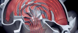
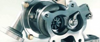
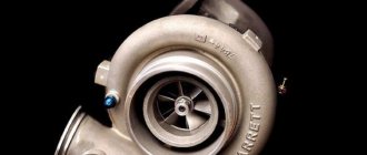
The main parts of a turbocharger are a turbine and a pump, united by a rigid axis. Their rotation, in one direction, at a high but equal speed, occurs as a result of the torque converted from the energy of the exhaust gas flow and acting on the turbine impeller, while the compressor draws in fresh air.
Turbine control with variable impeller geometry: operating principle
A turbine with variable impeller geometry was invented as a means of compensating for the consequences of turbocharger design flaws such as turbo lag, while at the same time reducing fuel consumption and reducing exhaust toxicity.
Turbojam occurs as a result of the specific operation of the turbine - the more gases that affect the impeller, the faster it rotates, which in turn leads to the pressurization of more air.
The problem is associated with this sequence, since the driver expects acceleration from the turbo engine at any moment, while at low speed there is nowhere to get enough gas and its pressure to instantly increase the speed of rotation of the impeller and, accordingly, increase power.
This delay, which occurs due to the fact that it is necessary to increase fuel injection, its combustion and entry in the form of exhaust gases, before the impeller rotation speed begins to increase, is called turbo lag. Its elimination became possible thanks to a turbine with variable geometry.
The operating principle of such a turbine is not too different from the original, except for changing the cross-section between the guide petals, which affects the speed of movement of the exhaust gases.
At low engine speeds, the gas flow is also not large, which does not allow rapid acceleration, therefore, at the moment the driver initiates acceleration, the signal from the turbocharger control unit reduces the distance between the impeller blades.
Although the amount of gases does not change, less space for movement at the same pressure increases their pressure, which speeds up the turbine speed. When the acceleration stops, the petals move apart again.
Changing the distance between the guide elements, depending on the type and model of the turbo engine, is controlled both by the compressor pressure (or lack thereof) and by the vacuum drive, and in some cases by a stepper electric motor.
In addition to fulfilling the main idea, such a turbine has other advantages over a conventional one:
- Great power.
- Fuel economy.
- Reducing exhaust toxicity.
What size turbine is needed? Turbine selection.
Since the choice of modes is a priority, then, contrary to the rule established by the compilers of training programs, the description of the search for the optimal dimensions of a turbo compressor should begin with its turbine part, but before that, let’s consider some general provisions.
The turbine is designed to spin the compressor part to those speeds that can provide it with the desired values of air flow and boost pressure. A small turbine will spin up faster than a larger one, given the same exhaust energy. Then, however, such a turbine will create a greater restriction on the exhaust flow, and this will cause back pressure in the exhaust manifold - an unpleasant side effect. This does not mean seeking compromise. The size of the turbine part, even when the main purpose of the selection is to ensure the highest possible spin-up speed, should keep the level of back pressure to a minimum.
Exhaust manifold pressure is a good indicator of how well the turbine part is matched to a particular engine. The lower the reading of the pressure gauge installed in the exhaust manifold, the greater the engine power. The exhaust manifold pressure should not exceed approximately 2.5 times the boost pressure.
The turbine's quick response to the gas pedal, early pickup, and, as a result, noticeable indicators of excess intake, which are praised by some manufacturer of small-sized turbines, will please only the owners of low-speed pickup trucks for transporting printed materials from a warehouse to a retail kiosk. For a passenger car, even in normal city driving with an irregular rhythm of movement, such little turbos become a problem, taking away up to 20% of the power at speeds slightly above average.
The turbine part selection process largely involves evaluating two parameters: turbine size and A/R ratio. The size of a turbine can generally be estimated by the diameter of its outlet (Fig. 1). Although this approach is, of course, crude, it still gives an idea of the potential of the flow of exhaust gases passed through the turbine. The choice of a turbine, in contrast to a compressor, is largely based not on direct calculations, but on the results of measurements (both independent and accumulated by predecessors and engineers in laboratories).
Based on the graph of the dependence of air flow in the compressor on the size of the outlet diameter of the turbine part (Fig. 2), constructed from the average statistical results of testing and testing of existing turbo engines, we can begin to consider a group of chargers that fall within the flow range of interest. A simpler formula for calculating flow (compared to the one given above) will be given in the chapter on compressor selection. Manufacturers of turbo kits have their own graphs of similar dependencies that better characterize their products. But in any case, the assessment for this indicator is very approximate.
Tuning and adjusting the turbine on a Volkswagen
Effective and correct tuning and adjustment of the turbine is important both for the efficiency of its operation, and for reducing the rate of wear of parts of the entire mechanism, and even for saving money on fuel.
This is due to the fact that incorrect operating settings or incorrect (untimely) turbine adjustments directly affect the entire vehicle and the ease of its operation.
While some actions usually mentioned in the instructions for servicing a car and its mechanisms can be taken care of by the owner independently, even without special tools, experience and knowledge - most of them will require the attention of a professional.
Every reasonable and caring car owner should remember such principles as: timely prevention and maintenance, as well as avoiding harm through one’s actions. This is true for both gasoline and diesel engines.
Additional system elements
There are a few additional elements worth considering separately. They are also included in the design of compressors and regulate certain processes.
Blow-off valve
A blow-off valve is also called a bypass valve. This valve is installed in the air system, usually between the diesel damper and the compressor outlet. The purpose of the valve is to eliminate emergency situations during operation of the unit. For example, during operation, the unit may go into an unwanted surge mode if this is not stopped in time.
This mode occurs due to high air flow speed. In this case, the compressor tries to close the throttle and wants to do it as sharply as possible. The occurrence of the regime is explained by the fact that the speed of the air flow due to the release of gases and the air flow itself begin to decrease sharply. The turbine, due to the force of inertia, continues to rotate rapidly.
If you do not reduce rotation, the consequences can be dire. One of the signs of such an air surge is an unpleasant sound that breaks through the compressor. Further ignoring the problem will lead to damage to the turbine bearings, which are forced to accept heavy loads due to the surges that occur.
The blow-off valve monitors the pressure inside the manifold and comes into operation if it begins to jump too much. The valve's functionality is ensured by a spring installed inside, with the help of which it is possible to prevent changes in the throttle position and improve the operation of the compressor.
If the valve does not have time and the throttle closes, then the blow-off begins to release excess pressure into the atmosphere. Thanks to such work, it is possible to reduce the risk of an accident and protect the turbocharger from heavy loads that can cause its failure.
Wastegate valve
The mechanical Wastegate valve is installed on the turbine or exhaust manifold structure. The main task of this part is to regulate the level of pressure, which gradually increases inside the compressor.
The designs of some diesel engines do not contain a wastegate, but in the case of gasoline units, the presence of such a valve is a mandatory requirement for its reliable operation.
Thanks to the operation of the wastegate, it is possible to ensure a problem-free and unimpeded exit for exhaust gases from the system. In this case, the exhaust gases bypass the operating turbine. With the help of such a distribution of gases, the required amount of energy is controlled.
Such forethought allows for effective control of the boost pressure inside the compressor. Control is ensured by a built-in spring that creates back pressure. It is this design that controls the bypass flow of exhaust gases.
The valve can be:
- Built-in. The design implies the presence of a damper, which is built into the housing. Housing is also called the “snail” of the main turbine of the unit. This element also contains a pneumatic actuator.
- External. This type of gate is a standard valve installed on the exhaust manifold. This valve has an advantage that makes it more popular than the built-in one. If necessary, the valve allows the bypass flow to be returned. In the case of sports cars, the vent valve vents gases directly into the atmosphere, preventing them from entering the turbine.
Both additional elements contribute to the smooth operation of the automobile turbocharger and prevent the occurrence of unpleasant situations that can lead to various accidents.
Where to buy and what is the price
You can purchase a turbine with variable geometry either at a car dealership or from another car owner, or via the Internet. Each option has its own advantages and disadvantages, but a successful result in terms of price/quality ratio is possible in each case; only the time spent searching for an offer differs.
The price of specifically variable impellers varies from 4,000 to 25,000 rubles, depending on the car make, turbocharger model, brand and quality (in terms of reliability and durability) of the product itself. One of the most deservedly popular models is the Garrett turbine, due to its quality and availability in different price ranges.
The cost of a turbocharger with variable geometry is not much higher, and sometimes not at all higher, than the option without it, since a turbine with variable geometry is higher in popularity and prevalence.
Drive unit
You may be interested in: Features of the design and repair of the VAZ-2114 starter
Among the drives, the most common are pneumatic options, where the mechanism is controlled by a piston moved inside the cylinder by air.
The position of the blades is controlled by a diaphragm actuator connected by a rod to the paddle control ring, so the throat can be constantly changed. The actuator drives the rod depending on the vacuum level, counteracting the spring. Vacuum modulation controls an electric valve that supplies a linear current depending on the vacuum parameters. The vacuum can be created by the brake booster vacuum pump. The current is supplied from the battery and modulates the ECU.
The main disadvantage of such drives is due to the difficult to predict state of the gas after compression, especially when heated. Therefore, hydraulic and electric drives are more advanced.
Hydraulic actuators operate on the same principle as pneumatic actuators, but instead of air in the cylinder, a liquid is used, which can be represented by motor oil. In addition, it does not compress, as a result of which this system provides better control.
The solenoid valve uses oil pressure and a signal from the ECU to move the ring. The hydraulic piston moves the rack and pinion mechanism, which rotates the gear pinion, causing the blades to be hinged together. To transmit the position of the ECU blade, an analog position sensor moves along the cam of its drive. At low oil pressure, the blades open and close as it increases.
Electric drive is the most accurate because the voltage can provide very fine control. However, it requires additional cooling, which is provided by coolant pipes (pneumatic and hydraulic versions use liquid to remove heat).
A selector mechanism is used to drive the geometry changing device.
Some turbine models use a rotating electric drive with a direct stepper motor. In this case, the position of the blades is controlled by an electronic feedback valve through a rack and pinion mechanism. For feedback from the ECU, a cam with a magnetoresistive sensor attached to the gear is used.
If it is necessary to rotate the blades, the ECU supplies current in a certain range to move them to a given position, after which, having received a signal from the sensor, it de-energizes the feedback valve.
Do-it-yourself turbine cleaning with geometry
A mechanism that faces continuous load and is exposed to combustion products of fuel and oils naturally requires periodic cleaning to prevent breakdowns and maintain operating efficiency.
In some cases, it is enough just to pour a special product and drive it through the turbine to clean it, but more often you will need to work with your hands. At the same time, you need to remember that under normal circumstances cleaning is a very rare need, and if the turbine requires monthly cleaning of carbon deposits, then there are problems in its operation. The reasons may be as follows:
- Excessive gas pressure.
- Replacement of turbine impeller bushings.
- Wear of gaskets.
- Exceeding the recommended service life of the piston compartment.
- Breather clogged.
In this regard, every car owner should remember that although independent cleaning is possible, its result does not always have a positive effect on the operation of the turbine, and sometimes it can even worsen the situation.
Lack of experience, special tools, and cleaning agents can negatively affect the geometry or even “kill” it, which is often encountered in repair shops - sandpaper, solarium and a hammer are not always useful for this mechanism. Remember that for cleaning in “makeshift” conditions, you must clearly understand what, with what and why you are doing it, providing an adequate replacement for the skills and equipment of professionals.
Operating principle of steam turbines
Steam turbines have the following operating principle: steam is generated in a steam boiler and then passes through the turbine blades under high pressure. As a result, the installation rotates, which produces mechanical energy. This energy is fed into a generator and used to generate electricity. The power of the system will depend on the difference in steam pressure formed at the inlet and outlet of the equipment. will select a steam turbine based on the operating principle of your enterprise and the assigned tasks.
For a steam turbine to be efficient and operate with minimal losses, the steam must be supplied at high temperature and pressure. Therefore, increased demands are placed on boiler equipment. The advantages of this technology for generating electricity are that it is possible to use any range of fuels, including solid ones. However, it is worth considering that solid fuels and oil fractions can reduce the environmental performance of the system.
| Code | power | speed | inlet pressure | inlet temperature | exhaust pressure | steam consumption |
| kW | rpm | MPa | WITH | MPa | Y/N | |
| M20 | 132-750 | 3000 | 0.5-2.35 | 225-330 | 0.15-0.3 | 3.54-13.86 |
| M21 | 250-1000 | 3000 | 2.0-2.45 | 260-390 | 0.2-0.98 | 4.76-33 |
| M30 | 300-700 | 3000 | 0.7-1.1 | 270-330 | 0.15-0.3 | 5.88-15.26 |
| M32 | 1000-2500 | 3000 | 2.35-4.0 | 390-450 | 0.78-0.98 | 23.36-43.7 |
| M40 | 250-1250 | 3000 | 0.8-1.0 | 250-330 | 0.15-0.55 | 4.6-21.5 |
| M60 | 1000-2000 | 3000 | 2.35-4.0 | 390-445 | 0.297-0.785 | 17.41-31-32 |
| M70 | 1000-2500 | 3000 | 0.6-1.27 | 260-300 | 0.2-0.5 | 23.2-48.8 |
| M51A | 750-1500 | 1500-6500 | 2.35-3.43 | 390-435 | 0.294-0.98 | 9.6-30 |
| T4 | 3000-6000 | 3000-6000 | 3.43 | 435 | 0.294-1.57 | 27.27-118.7 |
| Condensing steam turbine | ||||||
| Code | Power | Speed | Inlet pressure | Inlet temperature | Exhaust pressure | steam consumption |
| kW | rpm | MPa | WITH | MPa | Y/N | |
| M80 | 1500 | 5600-3000 | 1 | 300 | 0.0103 | 8.8 |
| Q02 | 1500 | 6500-1500 | 2.35-0.2 | 390 | 0.0103 | 8.4 |
| Q03 | 3000 | 5600-3000 | 2.35-0.2 | 390 | 0.0103 | 16.1 |
Advantages of steam turbines:
One of the advantages of steam turbines is that different types of fuel can be used to produce steam. After all, the main task is to ensure its uninterrupted supply, according to the technical specifications. will help you select a steam turbine according to your technical specifications. Steam turbines have deservedly taken their place in Russian industry; their good efficiency is determined by the following advantages:
- wide choice of coolant;
- use of various types of fuel: solid, gaseous, liquid;
- large power range;
- high power;
- long installation life.
Variable geometry turbine repair
Partially, as in the case of cleaning the turbine yourself, it is much easier to prevent the occurrence of a situation when it needs repair, with the help of competent and regular maintenance, than to try to correct the situation yourself.
Many car owners are scared by the cost of repairs, but they forget that doing it yourself is also not free, while it takes many times more time than a professional would spend, and besides, it can have negative consequences on the mechanism or be completely unsuccessful.
Therefore, without having the appropriate knowledge, skills and equipment, it is better not to try to repair the turbine yourself.
At the same time, it will be useful for you to learn about the most common turbocharger problems and their causes:
- Engine oil contaminated with large or small abrasive particles.
- Occurs as a result of initially low-quality oil, with a composition different from the original or initially unsuitable for use with a specific turbocharger model. In addition, dirt can get into the oil from improperly cleaned turbine parts or contaminated parts during repairs or adjustments.
- Long-term or constant operation of the turbine at maximum parameters. Exceeding the limits applies to both the temperature and the rotation speed of individual parts. It occurs as a result of damage to individual parts, their wear, or as a result of incorrect configuration/adjustment/repair of the turbocharger, which disrupts the operation of individual elements and increases the load on others.
- Lack of lubrication or its quality. It may occur due to the fault of the driver, poor quality of lubricant or mechanical damage to the turbocharger elements, preventing the normal action of the lubricant.
Of course, there are many more options for breakdowns and their causes, but the driver does not need to know them all in order to properly take care of his car - the main thing is to do everything that depends on him efficiently, and to give the car to professionals for technical inspection on time. It is much faster, cheaper and easier to prevent problems with a turbocharger than to solve them.
Schematic diagram
To understand how a turbine works, you should familiarize yourself with the operating procedure of the internal combustion engine.
As a rule, most engines are four-stroke piston engines; their operation is always controlled by the valves of the intake and exhaust groups. One cycle of work is four strokes, which take place in two full revolutions of the crankshaft. The principle of operation of a turbine on a diesel engine is quite simple and consists of the following actions:
- intake - the piston goes down, allowing air to penetrate through the intake valve;
- compression - at this moment the combustible mixture is compressed;
- expansion process - fuel enters under pressure and ignites;
- release - the piston goes up, releasing gas.


