Lada 2110 › Logbook › Repair and modernization of the VAZ 2110 generator.
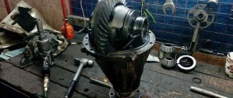
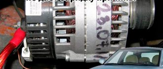
I see a lot of records about the repair of generators 2110. This is a real problem, not only does the low voltage prevent the equipment from working fully, but it also kills the battery, especially if it is Calcium and its charge voltage is higher than the standard one in 2110. Noise and “wedge” of generator bearings, and very often rotation noise is due to a broken diode bridge or breakdown of the stator or rotor windings (and this happens, and it has nothing to do with the bearings). Previously it happened often, now less often with capital generators. This is even now lying on the balcony:
I would like to share recommendations for repairs as an auto electrician (which I can voice). I see a lot of mistakes made by citizens here when making repairs. When starting to disassemble, many are faced with the problem of dismembering the front cover-stator-rear cover, aluminum-iron-aluminum with corrosion creates a strong “pie”, only soaking in WD 40 and time can help. After disassembly, the first thing you need to do is “ring” all the windings - the stator:
Usually it is rearranged from the horseshoe formation. So don't lose it. When installing a horseshoe, especially a new one, you need to clean the contact area of the main minus, and you can lubricate it with electrical grease. :
Replacing bearings is not a rewarding task. In addition to the fact that the pulley on different generators is screwed on differently (most often it is deformed when removed, and must be replaced with a new one), the individual bearings themselves are almost 98% left-handed, and many are sold pressed into covers (they are different) and the bearings themselves are also different depending on the shaft... in general, it’s still a pain in the ass.
People are also trying to buy a new generator and increase the voltage or power (do not confuse the concepts). Yes, now, according to the new technical regulations, generators are standard 80A or 90A, there are Grands 120A, previously there were 70A. But this doesn't always help. To increase power
10-15% of the generator is often connected to the “middle point” of the stator windings, i.e. our generator has 3 windings, they are connected in the middle by a “star” and is not used for ordinary people:
Another tap is made, and the horseshoe is changed from 6 diodes (3 windings - 6 diodes, standard) to a horseshoe of 8 diodes:
This is how the scheme will turn out.
This gives less voltage drop when all consumers are turned on. To increase the voltage
put an additional diode in the excitation circuit, i.e. “cheat” the generator. The generator windings can withstand an increase in voltage up to 25 V. But we don’t need this. The sold “3-position voltage regulator” is designed in the same way - there is a diode and a switch. This measure allows you to increase the voltage by 10% depending on the selected diode and its reverse current.
More details on the website 2111.rf. I’ve done this more than once, it really helps, especially with charging the battery. The main advice as an auto electrician is to throw away old generators right away! Gone are the days when it was expedient and profitable to repair a “thing.” They are outdated and completely worn out. The rubbish (more than 10 years old) that they bring in now is not realistic to repair, this is not 5 years ago. Therefore only new. And calm and reliable. And as the electricians say, “God save us and ground us!”
Replacing the generator diode bridge on a VAZ 2110, VAZ 2111, VAZ 2112
Welcome! Diode bridge - it gives a charge and gives it an even charge (the generator gives a jumping charge, and this bridge straightens it) to the battery when the car starts and the generator starts working, which is why when the diode bridge fails, the battery is immediately discharged and upon arrival one day day in the car, the car cannot really start and you have to push it, or take it on a cable, one thing is good, when the diode bridge fails, the battery charge lamp on the instrument panel will immediately notify you about this, and if a person knows even a little about cars , then he will already understand what happened and in the near future he will drive the car to a service or to a garage and in the garage, checking the generator brushes, determine whether the diode bridge has become unusable or the brushes and, if necessary, replace the worn part with a new one.
Note! To replace the diode bridge with a new one, you will need to stock up on: All the keys that are present in your set and screwdrivers, but if you want to check the old diode bridge for functionality, then take a multi-meter (And we recommend that you check it)!
Summary:
Where is the diode bridge located in the generator? Let's start with the fact that cars of the tenth family were equipped with different engines, different body kits (We are talking about the VAZ 2112 coupe) and, accordingly, such parts as a generator, depending on the engine, were also different, but in the injection system, with an 8-valve engine, one type of generators, with 16 valves, is completely different, carburetors also had their own generator, usually 55 amperes, because in carburetor cars there are many times less electronics and they only needed the generator that was installed on them, well, in this article we will only analyze one generator, marked 9402.3701 (It was used on fuel-injected 8-valve cars), the photo below shows just such a generator, it is very easy to disassemble, as you can see, the cover of such a generator is not secured with bolts but simply with latches (indicated by red arrows) By bending these latches, you can easily remove the cover and see behind it the diode bridge, which can be seen very clearly in the small photo.
Note! As for the generator marked 37.3701, which was used in carburetor eight and nine engines (later they began to install these engines on dozens, this generator migrated to them too, like the engine itself), it looks completely different and produces clearly less amperes (55 amperes, against 80 or some even go to 90, the latter, by the way, are absolutely identical in appearance to 80 amps and are even interchangeable, so if you are the owner of an 8-valve injection engine, you can install a generator with a little more amperes if 80 is not enough for you and the installation will be absolutely identical) but this is enough for the carburetor, the diode bridge in such generators is also not difficult to replace, you just need additional tools and more time, and also care is needed, because if the generator is not assembled correctly, then it can short-circuit and damage the wires that The batteries go and the battery itself will burn, so be extremely careful and attentive when assembling the generator in the car! (How to replace the diode bridge on a carburetor, read the article: “Repairing a generator on nines”)
When do you need to change the diode bridge in the generator? 1. Only by checking it can you find out whether the diode bridge can be replaced or whether it will last a long time, it is checked only with the generator removed, so as soon as you remove the generator, remove the plastic cover from it and the bridge itself, so that it is convenient to work with it and hold it, after all the operations done, turn on the multi-meter as shown in the photo below (It needs to be turned on in ohmmeter mode) and connect to the diode bridge, namely to the common bus of auxiliary diodes (Number 1) a red probe, and the other, black , to the terminal of the diode (Number 2) that you want to check (You need to check all the diodes, so connect the black wire in order and just always remember, the diode should not pass current, if this suddenly happens, the multi-meter will immediately show infinity and this will indicate that the diode bridge is faulty and needs to be replaced).
It will be useful: Citroen C4 air filter: where it is and how to determine the need for replacement, choosing a new part and step-by-step instructions for self-installation
Note! Let us explain to you what infinity is, it’s just that not everyone knows it, in general, infinity is indicated differently on different testers, for some it simply does not react (For example, it was 0, and it still stands after connecting the probes coming from the tester), while for others the tester shows 1 and stands firmly on this number (In this case, the readings should not move, that is, before connecting the tester showed 1 and after connecting also 1, this is infinity, but if it happened that it showed 0 and after connecting 1, this is already indicates that the diode being tested has resistance), but if there is suddenly resistance, then the tester will definitely have to show the result (see photo 2 above), if in your case this happened with all the diodes being tested, then your bridge is not subject to replace with a new one!
2. The second, final test, the black probe is connected to the plate of the generator rectifier block, inside which is the diode that you are going to check, and the other, red probe, is connected to the terminal of the diode itself, a working diode should not pass current and thus the tester will not should give a value of infinity, then swap both probes (see photo 2) and the tester will definitely have to give some value of several hundred, if everything turned out exactly the same for you, then the diode bridge is working and what else is the problem (B stator for example or in brushes).
Multimeter testing method
The most informative is a full check of the diode bridge. To implement it, you will need a multimeter, tester or Tseshka - any of these devices is equally suitable for measurements.
Follow these steps:
Time spent checking: 10 minutes
Determine the purpose of the pins.
The method is universal, so you can check both the diode rectifier as an assembly and the design of individual parts without disassembling them.
Install the multimeter probes.
Install the multimeter probes into the appropriate connectors on the device, observing the color markings (black - minus, red - plus). Switch the switch to dialing mode.
Use the negative lead of your multimeter.
Connect the negative probe of the multimeter to the plus of the diode bridge, and the positive one in turn to each of the AC voltage terminals.
As a result of touching, the opening voltage of the diodes should be displayed on the multimeter display; at both points this measurable value is the same for each measurement. Otherwise, the assembly is faulty.
Swap the tester probes.
Next, you need to swap the tester probes - set the red one to positive, and alternately touch the black leads to the AC voltage terminals.
The display will display a unit, indicating an infinitely high resistance - with reverse polarity, the diodes remain closed. Otherwise, if any voltage is displayed, the bridge is broken.
Use the positive lead of your multimeter.
Touch the positive probe of the multimeter to the negative terminal of the diode bridge, and touch the negative terminal in turn to the variable terminals. In both cases, the voltage drop should be displayed on the display.
Use the black probe.
Install the black probe on the negative terminal of the assembly, and connect the red probe to the variable terminals. There must be a unit in both positions on the multimeter, otherwise the element is broken.
The respectful “Gennady” or the familiar “Gena” are written with a small letter for a reason! This is not the name of a car mechanic, but a humorous slang nickname for an electric generator - one of the most important components of a car, which has practically not changed its design over several decades. Let's take a closer look at Gennady, studying its strengths and weaknesses and understanding on what fronts we can expect surprises regarding the electrical part of the car.
"Child of Light"
And the car generator in the modern sense is generated by mankind’s love for electric light. Cars from the dawn of motoring had only a simple unit called a “magneto” - a miniature generator combined with an ignition breaker, integrated into the engine housing and producing exclusively high-voltage impulses for the operation of spark plugs. Neither a lamp nor any other consumer of electricity could be connected to the magneto, so cars of the 19th century illuminated the road with carbide lamps in which acetylene burned - there was no need to expect help from the internal combustion engine.
However, it soon became obvious that the car engine must generate more electricity: not only for its own operation, but also for the operation of external consumers - headlights, horn, front panel meters, battery charging and the like. Therefore, next to the high-voltage “spark” winding of the magneto, an additional winding appeared - a low-voltage one, providing on-board voltage. MAGneto + DYNAMO machine = Magdino. This is how the first generators came to be called.
But since magneto and magdino are traditionally built directly into the engine, their power is limited by their small dimensions. And as soon as it became clear that an increase in generator power was inevitable, the “gene” became external - it moved to a bracket on the cylinder block and began to receive rotation from an external transmission - a belt, and sometimes a chain or gear.
The first generators produced direct current, but after the development of the semiconductor industry in the mid-twentieth century and the advent of powerful rectifier diodes, generators began to produce alternating current, which was then rectified to constant current by diode bridges. Changing the type of current made it possible to stepwise reduce the size and weight of generators several times and increase their power.
Actually, a modern generator is almost identical to what was on machines developed 10, 20, 30, or more years ago. Engines and gearboxes become more complex year after year, but perhaps the main external electrical unit remains virtually unchanged. Its design is not ideal, but it represents a golden balance of properties and cost. However, additional components and improvements appear - for example, instead of a simple pulley for a belt, an overrunning clutch can be installed on the generator, as in a starter bendix, or the number of coils in the stator winding increases and the diode bridge becomes more complicated, but most generators still make do with the classic design.
How does the generator work?
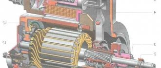
The two halves of the body, cast from aluminum, form a “barrel” and are bolted together. Inside the “barrel” there is a ring winding - a stator coil, from which we remove alternating voltage. A diode bridge is connected externally to this winding, covered with a plastic protective half-cover and converting the alternating voltage into a constant one. An axis passes through the generator housing - a shaft rotating on two bearings and driven by a pulley by a belt from the engine crankshaft.
A rotor with a coil inside – an electromagnet – is installed on the generator shaft and rotates with it. Through a pair of sliding contacts and carbon brushes, a voltage regulator supplies control current to it, ensuring that the generator produces 14 volts at the output - without a regulator, the voltage value will depend on the speed and can reach several tens of volts, dangerous for 12-volt automotive electrical equipment.
Generator faults
The generator on most machines is quite simple in design, and thanks to this, the number of types of its malfunctions is small, and diagnosis is simple. “Floating” problems that are difficult to catch and localize almost never happen there.
The weakest components of the generator are not mechanical, but electronic: this is a diode bridge, consisting of six powerful diodes, combined into three groups on an aluminum radiator plate, and a voltage regulator. They fail due to overload (due to systematic operation with overload from abnormal current consumers, if you light someone else’s car without turning off your engine, or due to a short circuit in the battery banks), due to the appearance of microcracks from constant shifting engine compartment temperature within a wide range and penetration of moisture into cracks, and sometimes for no apparent reason at all - this happens with electronics... In addition, the graphite brushes in the voltage regulator wear down over time. In this case, both the diode bridge and the voltage regulator assembly with brushes can be replaced with new ones.
In second place for failure are bearings. There are two of them in the generator - the more powerful and massive front one, and the rear one - smaller in size. The front one most often suffers, since it bears both the load from the tightly stretched belt and the penetration of dust and moisture from the outside. The bearings manifest themselves with a hum and squeal, which disappears if you start the engine with the alternator belt removed. They can also be replaced with new ones.
In third place are more unpleasant malfunctions, although, fortunately, more rare. Two copper rings on the shaft can be ground down to the ground - contacts for powering the rotor winding, along which the graphite brushes of the voltage regulator slide. These rings are quite durable, since the brush springs are weak, but after using several sets of brushes, the rings can become unusable over the years. They are not always found as spare parts, and you may not find them for a specific generator model... If you manage to buy them, then they are removed from the shaft in one block (filled in plastic), and new ones are installed in one block.
Even from old age, the insulation of the stator winding wires can deteriorate and a short circuit between the turns can occur. As a rule, it is not profitable to repair this, although in principle rewinding is possible. Malfunctions such as housing destruction are probably not worth considering, although they certainly do happen, and, oddly enough, some domestic generator manufacturers supply halves of the “barrel” for retail sale.
Generator repair
Now let's look at generator repair using a live example. A VAZ-2115 car arrived for service with the problem of the battery not charging. The electrician, to his credit, did not condemn without looking (as is often done) the diode bridge and the regulator en masse, but first checked the wiring to the generator, then (without removing the generator from the car) removed the voltage regulator from it and checked it using an external a voltage source of 15-16 volts and a load lamp, simulating normal operation - the regulator turned out to be working. The regulator brushes, slip rings on the shaft and the rotor winding were also intact. After that, the master shone a flashlight on the diode bridge, saw a charred diode, concluded that the bridge was faulty... and suggested a complete replacement of the generator!
Why? It’s simple: our generator, produced by the Rzhev Automotive and Tractor Electrical Equipment Plant ELTRA, model 5102.3771, is equipped with an 80-amp diode bridge MP13-80-3-2, which costs in the store... 909 rubles, and it doesn’t change like, say, the old one - the good “nine”, where this was done with a screwdriver and without removing the generator from the car. In our case, the bridge is changed using a powerful soldering iron, and for this, the generator, in an amicable way, should lie on a workbench. This is a fair amount of fuss, which also requires a certain amount of accuracy. The master did not want to deal with this for less than 2,000 rubles, and hinted to the owner that the cost of spare parts and repairs of almost 3,000 rubles for a 2006 generator looked pale compared to the price of a new assembled generator of 4,450 rubles. In other words, you can fix it for 3,000, or you can get a new “gene” under warranty for an additional 1,500 rubles on top of the repair price, with new bearings, windings, guaranteed to be free from fatigue cracks in the varnish, and so on. The owner agreed with these arguments, and the generator was replaced with a new one.
Here's an unexpected outcome... We wanted to watch an inexpensive restoration repair, but we were faced with a large-scale, expensive replacement. However, the repairs have already been completed, the car regained mobility and drove away, and we had the opportunity in a calm atmosphere to carefully look at the generator from the inside, study the design and figure out whether the master was right. Moreover, no one forbids us to fix it ourselves.
Generator from the inside
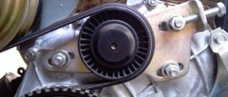
We begin disassembling the generator by removing the pulley from the shaft: carefully clamp the 6-ribbed pulley under the poly V-belt in a vice through aluminum spacers and unscrew the nut with a pneumatic impact wrench. Light traces of jamming on a pulley are not dangerous if they are controlled and predictable - neither the grooves nor the edges are deformed.
A groove for the key is visible on the shaft, but there is no key itself, nor is there a groove for it in the pulley. On this generator, the pulley is fastened by friction - by tightening the nut with a screw against the inner ring of the bearing, and through it - into the rotor.
We remove the plastic “half-cover”, under which the diode bridge and voltage regulator are hidden. We see that the bridge is faulty - at least one diode out of six is broken. This is noticeable even without checking with a tester - it is clear that the diode is charred.
The voltage regulator is easily removed by unscrewing two M8 nuts. It has already been checked electrically, and visually it is also clear that the brushes are slightly worn. Blow, wipe and set aside.
How to replace the generator diode bridge on a VAZ 2110-VAZ 2112?
Removal: First, remove the generator from the car (For detailed instructions, read the article: “Replacing the generator on a VAZ”) and then snap off the latches on the sides that secure the cover to the generator (How to snap them off, read in the same article, just a little higher) and it remove, and as soon as it is removed and set aside, proceed to removal, first with a screwdriver or wrench (everyone has a different way of attaching the voltage regulator), unscrew either the screws or bolts securing the regulator (see photo 1) and pulling remove it, disconnecting the wire connector from the regulator (see photo 2), then using a spanner or socket, unscrew the three bolts (indicated by numbers 1 in photo 3) that secure the wires to the diode bridge and unscrew another bolt that secures it diode bridge (Indicated by number 2) and having removed the wires, throwing them aside, use a Phillips screwdriver to unscrew the screw that secures the capacitor (see photo 4) and remove the diode bridge and capacitor from the car generator.
Note! Screw all the bolts that you will unscrew strictly into their proper places, so remember them all or mark them with a marker, this is mandatory, because if you mix up and screw the bolt that goes without an insulating and thrust washer into the wrong place, the generator will simply short out to ground and work will not be!
Installation: Installation of the diode bridge is carried out in the reverse order of removal, the whole operation is carried out easily and quickly, the main thing is to assemble everything correctly, do not forget and be sure to read the video at the end.
Additional video clip: Be sure to watch the video located just below, it will warn you against incorrect installation of the diode bridge and short circuit; after installing the generator, if you do everything correctly, there will definitely not be any.
Note! If you want to see clearly how you can check the diode bridge for serviceability, then in this case, check out the video below:
Using a light bulb and battery
A fairly simple way to test a diode bridge is to use a battery and a light bulb, which almost everyone can find at home. This method is no more complicated than the previous one, the lamp acts as a control, and the battery acts as a low-voltage power source. The battery is selected in accordance with the parameters of the diode itself. To check the serviceability, you need to separate the diodes from the bridge separately and assemble a simple circuit:
Rice. 3. Test diagram with a light bulb and battery
As you can see, you need to assemble a serial connection from the contacts of the light bulb to the battery and the diode itself.
- The first stage is the correct connection, when the plus of the battery is connected to the positive plate of the rectifier, and the minus of the battery to the negative plate of the rectifier. If the diode is working properly, then current will flow in the circuit and the light bulb will light up.
- The second stage consists of turning the diode over, when the positive terminal of the rectifier is connected to the negative plate, and the negative terminal to the positive plate.
Reverse test circuit with a light bulb and battery
If the diode is working properly, no current will flow and the light bulb will not light up. From a practical point of view, you don’t have to look for a battery, but make do with any available power sources whose rating is comparable to the rating of the diode bridge and each element. For example, in a garage you can connect to a car generator or battery terminals.
How to correctly replace the generator diode bridge on a VAZ 2110?
As you know, a car generator is designed to provide power to all electrical equipment in the car when the engine is running. This unit in domestic “tens” consists of many elements that ensure its optimal operation. One such device is a diode bridge. What functions does it perform, what do you need to know about its malfunctions, and how is the diode bridge of the VAZ 2110 generator replaced? You can find answers to these and other questions below.
Rectifier design
In the literal sense, a rectifier is not able to “straighten” alternating voltage. This unit received its name because of the operating principle of the diodes included in it:
- alternating current periodically changes the direction of movement in the circuit;
- diodes pass it in only one direction and cut off currents of reverse polarity;
- so that power surges in the network are invisible to the powered consumer, 3 diodes are installed in one direction, the remaining 3 in the other.
Currently, high-power diodes have a classic design; low-power semiconductor devices of this type are made in the form of a silicon junction on a board. However, to remove high temperatures from the body or silicon junction, both modifications are either embedded in the heat sink plate or equipped with their own individual radiators.
If a silicon junction or a full-fledged diode in the housing breaks down, the diode bridge of the generator or individual semiconductors included in its composition must be replaced.
Main diode bridge
The lower figure shows sinusoids and the direction of current movement in the generator and diode bridge.
The positive value is conditionally taken to be the voltage directed to the 0 point of the stator winding. After the rectifier, the current in the consumer load flows only in the positive direction, that is, from the “+” of the generator to its mass “-”.
Therefore, the power diode bridge (main) uses large-sized 25 - 30 A diodes, the power of which can be further increased due to the additional rectifier arm discussed below.
Unlike other components of the “auto power plant”, a visual inspection does not allow us to identify any faults in the diode bridge of the generator. The rectifier requires only hardware diagnostics with a multimeter.
The diodes are located on a horseshoe-shaped heat sink plate under the back cover of the generator. On remote rectifiers, the diode bridge is located near the generator; instead of plates of the classical configuration, a regular board can be used. In this case, a finned radiator is placed on the body of each diode.
Additional diodes
The main difficulty in the design of a car generator is that the excitation winding of its armature is also a consumer of constant voltage. This coil uses the generator's own diode bridge:
- 3 additional diodes cut off the battery current when the engine is not running;
- negative diodes are taken from the main (power) bridge of the generator.
Instead of powerful semiconductor devices, small-sized 2 A diodes are used.
Zener diode
Since the amount of voltage generated by the machine’s generator directly depends on the speed of the crankshaft, which transmits torque to its pulley, “spikes” of up to 20 V are possible in the on-board network, which is harmful for consumers. To eliminate frequent repairs, the easiest way is to connect the rectifier diode bridge via a zener diode:
- this semiconductor device cuts off current of reverse polarity by analogy with a diode, but only up to a certain value called stabilization voltage;
- when the voltage from the stator windings increases to 25 - 30 V, the zener diode begins to pass excess voltage, but in the opposite direction;
- At the “+” terminal of the generator, the correct current value for the on-board network and battery charging is maintained.
When diagnosing a rectifier, checking the diode bridge of the generator with a multimeter is carried out indirectly:
- a normal diode should have “infinite” resistance in one direction, 500 - 700 Ohms in the opposite direction;
- If, when moving the tester probes, the ohmmeter readings do not change, the indicator displays 0 or infinity, the diode is broken and needs to be replaced.
The check is described in more detail in the following paragraphs of this manual.
Additional rectifier arm
Phase voltages are characterized by a deviation of the voltage graph from a sinusoid. Therefore, a generator circuit with an additional rectifier arm is only possible when the stator windings are connected in a star:
- the shape of the phase voltages in this case differs from the sinusoid by the harmonic value;
- this characteristic (third phase harmonic) is present only in phase voltage and is absent in linear voltage;
- The harmonic power can be used as an additional arm by adding diodes at the 0 point of the stator phase windings.
This is interesting: Replacing a window regulator on a VAZ-2107 with your own hands: step-by-step instructions
The size of the shoulder is 5 - 15% of the generator power, but it occurs only at speeds above 3000 rpm. The durability of the rectifier also depends on the performance of the voltage regulator. But repairs are available to the owner of the car after disassembling the generator.
Description of the diode bridge on the “Ten”
How is the diode modified and installed in the device? For what reasons can a bridge fail? To begin with, we suggest that you familiarize yourself with the description of the part. If you dismantle the generator assembly from the car and remove the cover, you will be able to see the diode bridge (DM), which is located immediately behind it.
Purpose and functions
What functions does the DM perform:
- The primary task of the device is to convert alternating current into direct current.
- The DM also performs the function of blocking current from entering the stator winding. In this case, the device actually performs the one-way valve option.
- In addition, the DM is designed to increase the safety margin of the generator unit. It allows you to protect the mechanism from the effects of adverse factors and contamination on the device, and this, in turn, can negatively affect the functionality of the mechanism as a whole.
Device
As for the device, in the factory configuration the DM for the “tenth” generator is a monolithic structure. This design, as a rule, is quite strong and reliable, is characterized by its small size, as well as a relatively low price. The only drawback characteristic of factory-made DMs is that if one of the diode elements burns out, local replacement of the damage will not be possible. That is, the car owner will have to completely change the factory axle with his own hands.
As for the design features itself, the DM consists of:
- two aluminum plates;
- spacers made of plastic;
- as well as nine diodes, which are connected to each other by soldering into one structure, that is, a bridge.
Purpose of the rectifier
Since alternating current generators are more advanced, compact and repairable compared to direct current modifications, a generator diode bridge is added to the design by default to convert alternating current to direct current.
In other words, without a rectifier assembly, electricity will be generated by the generator windings, but will become unusable for the on-board network and battery. Headlight lamps, air conditioning compressor windings and electrical circuits of other consumers will burn out, and the engine will not be able to start.
Possible malfunctions: signs and causes
As stated above, the purpose of diode elements is to convert alternating voltage to direct voltage. If one of the diode elements fails, then its malfunction may be indicated by such a sign as a decrease in the voltage level, as well as power in the vehicle electrical network.
It will be useful: Towbar for Mitsubishi Lancer 10: do-it-yourself installation
For what reasons may problems occur in the operation of the DM:
- Manufacturing defects. As practice shows, many modern DM manufacturers use aluminum shells of fairly low quality in their production. Accordingly, this affects their reliability as a whole. That is why it is recommended to use DM equipped with steel shells, since this directly affects the service life.
- Moisture gets inside the device. Regular exposure to moisture can cause oxidation, in particular, on the surface between the device body and diode elements.
- Engine fluid getting into the unit is one of the most common causes. Exposure to lubricant can lead to disruption of the functionality of the device as a whole, especially if it gets inside the generator unit, directly on the DM.
- Another reason why DMs on “tens” often fail is the polarity of the battery is reversed. If you connect the battery to a charger or accidentally reverse the polarity while “lighting up” the car, this will most likely cause the motor to burn out. Therefore, you should always remember that plus is connected to plus, and minus is connected to minus.
- Regular operation of a vehicle with a weak battery. If the battery does not pull the load and constantly operates under conditions of reduced charge, then the reason may be the inoperability of the DM.
Diagnostic methods
As practice shows, diode bridges periodically fail on any vehicle, regardless of the make and model. It is also not fundamentally important whether you use diode bridges from Valeo, Bosch or any other manufacturer.
Most often, one or several diodes burn out in a DM. As for the reasons, here we can highlight:
- dust ingress;
- negative impact of dirt;
- contact of diodes with oil;
- accumulation of moisture in the generator;
- polarity error when lighting;
- incorrect battery connection;
- overload in the electrical network;
- errors in the installation of electrical equipment;
- factory defects, etc.
If you set a goal, the bridge can be checked in normal garage conditions. For such tasks, use a light bulb or a multimeter.
Before starting work, remove the protective casing from the DM, and also do not forget to disconnect the terminals on the regulator. Remember that all bridges are positive, that is, positive diodes are equipped with red wires, and negative ones are black. Don't get confused.
Now in more detail about each of the methods.
Multimeter
If you decide to use a multimeter to check the bridge, you will need to perform several sequential procedures.
When to do a wheel alignment: signs and regulations
- the bridge is dismantled from the generator (no other way);
- each diode will need to be checked separately;
- the beeper mode is selected on the measuring device;
- This setting will allow you to hear a signal when the probe is shorted;
- if this mode is not available, select the 1kOhm position;
- the probes are brought to the edges of the diode;
- a measurement is made;
- the probes are swapped.
Now regarding the measurement results. Everything is fine with the diode, if in one position you see an infinity sign on the screen, in the second it gives a value in the range from 500 to 700 Ohms.
This is interesting: Reasons why the car stalls when braking and troubleshooting
If the device shows a lower resistance value, or there is an infinity sign in two positions, you have found a faulty diode.
The multimeter switches to resistance measurement mode (range 1 - 2 kOhm) or continuity with a sound signal. Before starting work, touching the contacts of the probes to each other controls the choice of the desired mode (reading 0 kOhm or sound signal, respectively).
Bridge diodes are divided into two types, conventionally called positive and negative. Positive diodes have a red body, and negative diodes have a black body. All diodes must be checked individually.
During the test, the multimeter probes are touched to the diode outputs and the result is recorded, then the probes are swapped. For a working diode, the resistance should be in the range of 400 - 800 Ohms in one position of the probes and become equal to infinity for a given range in another (the presence of a buzzer in the first case and its absence in the second).
If there is a different combination of test results (small + small or large + large resistance according to the indicator, or sound + sound, no sound + no sound), the diode is considered to be faulty.
Bulb
Now let's see how the procedure is carried out using a regular light bulb. This is a good alternative for those cases when you don’t have a multimeter.
The most ordinary 12 V lamp will do the job.
Snow chains or wheel bracelets: how they work
- The DM housing is connected to the negative of your battery;
- the plate must fit tightly to the car generator;
- one end of the lamp is connected to the minus of the generator;
- the second to the positive terminal 30 through the battery;
- if the lamp is on, then one or several diodes have failed;
- check negative diodes;
- the minus of the lamp goes to the body of the autogenerator;
- plus to the axle mounting bolt;
- if the lamp lights up or starts blinking, the problem is with the negative diodes;
- Next, the positive diodes are checked;
- the plus goes to terminal 30, and the minus also goes to the mounting bolt;
- when the lamp is on, we conclude that the problem is with this group of diodes;
- additional bridge diodes also need to be tested;
- the minus remains in its place, and the plus goes to terminal 61;
- if the lamp is on, the problem is diagnosed again.
To solve the identified problem, you will need to remove the problematic diode. A new one is installed in its place.
Nobody forbids you to simply buy a completely new DM and install it in place of the old one, then the question is a more substantial amount of money.
In total, checking and repairing the bridge will take no more than 2-3 hours for a technician without much experience. If you are an experienced auto mechanic, then you definitely won’t spend more than an hour of your time on such events.
Have you had any experience in repairing or simply checking diode bridges on your car? If yes, write about it, tell us what difficulties you encountered or what tricks you know.
That's all I wanted to say. Thank you for attention! Subscribe, leave comments, ask questions and expect a lot of new, useful and interesting materials!
Diagnostics
The diagnostic procedure must be carried out on a dismantled generator device, so the unit must first be removed. When the mechanism is dismantled, the plastic cover is removed from it, as mentioned above, the DM is located immediately behind it (the author of the video about self-diagnosis with a multimeter is Ramil Abdullin).
For diagnostics you will need a tester - a multimeter - the test is carried out as follows:
- First, the multimeter should be activated in ohmmeter mode. Having done this, the positive probe of the tester must be connected to the diode bus.
- In the same way, connect the negative probe of the tester to the corresponding contact on the diode bridge.
- Next, you need to monitor the tester readings. If the diode bridge is in working condition, then the tester display will show values close to infinity. If there are no such values, then most likely the DM is inoperative and should be replaced. But the diagnosis does not end there.
- Next, you will need to swap the location of the probes, that is, the negative contact is connected to the positive one and vice versa. Having done this, again look at the multimeter reading on the display. If there are no failures in the operation of the DM and the device as a whole is functioning normally, then a value of several hundred Ohms should appear on the tester screen.
- If the DM is equipped with an additional diode, then you can check it too. In this case, the diagnostic procedure is performed in a similar way; you just need to repeat all the steps.
Photo gallery “Self performance test”
How to check without dismantling
You can diagnose the device on site without disassembling the generator or desoldering the part. To do this, unscrew all the wires on the generator and voltage regulator, set the tester to ohmmeter mode, and connect the lamp to the battery in the manner described above.
This method allows you to check the serviceability of the entire bridge and individual groups.
Short circuit
For this test, the positive electrode is applied to output 30 of the generator (“plus” of the power rectifier), and the negative electrode is applied to the housing. A resistance value of 1 indicates that the bridge is in good condition.
One end of the lamp is connected to the negative terminal of the generator, the other to the positive terminal. A lit lamp indicates a short circuit.
Negative group
The negative electrode of the tester is connected to the frame of the generator, the positive electrode is connected to one of the diode bridge mounting bolts. The negative group is operational if the resistance is infinity.
This is interesting: Checking diesel engine injectors, malfunctions and cleaning
To check with a lamp, connect its minus to the generator casing, and the plus to the axle mounting bolt. The lamp lights up or flashes when there is a malfunction in the negative group of elements.
Positive
The positive probe of the multimeter is connected to the positive terminal, the negative one to the bridge mounting bolt. With a working group, the resistance is infinite.
The negative of the lamp is connected to the bridge mounting bolt, the plus is applied to the positive terminal. A lit lamp indicates a short circuit in the positive semiconductors.
DIY replacement instructions
In the event of a breakdown, the repair of the DM consists of its replacement, which is done as follows:
- First you need to turn off the ignition, open the hood and turn off the power to the on-board network; to do this, disconnect the battery.
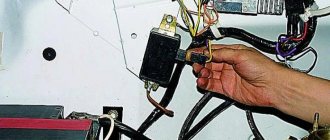
- Once the battery terminal is reset, you will need to disconnect the pink cable responsible for activating the generator assembly. The wire itself is fixed with a bolt and nut; the nut itself will need to be unscrewed.
- Now you need to slightly loosen the tension on the top as well as the bottom nuts. Unscrew the tension screws and remove the strap. Inspect it - if the belt shows signs of damage - cracks, delamination - then it is better to change it immediately. If the strap is intact, set it aside.
- After completing these steps, you need to rotate the generator mechanism 90 degrees, this is done so that you can access the lower mounting screw. Unscrew it.
- Next, carefully inspect the body of the dismantled unit. If necessary, clean - there should be no dirt, especially on the connections. Dirt getting inside the generator housing can also lead to its incorrect operation and even failure. Bend the fasteners and remove the cover.
- Next, you need to clean the inside of the rings as carefully, but most effectively as possible.
- After this, all you have to do is dismantle the failed DM and replace it with a working part. When the installation is completed, the structure is assembled in the reverse order. Do not forget to tighten the strap, just make sure that it is not too tight, this is important. Having done this, you will need to start the engine of your car and diagnose the operation of the new DM.
Replacing the generator diode bridge on a VAZ 2110
When the generator is turned on, it produces direct current. But to power all consumers in the car and recharge the battery, alternating current with a clearly defined frequency is required.
The diode bridge performs the functions of converting direct current into alternating current. This device is also called a rectifier.
Element appearance
Diode bridges can have different designs. However, cars are mainly equipped with three-phase rectifiers. This is due to the important advantages that they possess. Namely:
- The output produces the most pulsating voltage;
- Three-phase devices are excellent for half bridges and diode bridges;
- Their design allows the additional use of a capacitor - a current filter.
Basic information regarding the structure and function of the diode bridge
The practical purpose of a diode bridge in a car is to generate a pulsating current as a result of DC conversion. The diode bridge has the following properties:
- mechanical, which ensure the functioning of the corresponding automated elements;
- electrovacuum, which provides the diode with an absolute degree of insulation;
- semiconductor, which coordinate the functioning of all structures of the diode bridge, etc.
Replacing a diode bridge on a VAZ 2110 generator
From a practical point of view, the role and function of the rectifier (diode bridge) is to autonomously convert alternating current into a given direct current, which has a certain pulsation frequency. Today there are many variations of the rectifier, however, in cars it is the three-phase one that is used, due to its functionality, namely:
- has the lowest pulsating voltage that is created at the output;
- ideal for both bridge and half-bridge diodes;
- allows you to additionally install a special current filter in the form of a capacitor (see Changing the capacitor (VAZ 2110 generator)).
Design features
- In the factory version, diode bridges for the VAZ 2110 are monolithic structures that are distinguished by their reliability, affordability, and compact size;
- The factory diode bridge has only one significant drawback - if one diode burns out, it is not possible to replace one element. You have to buy a new factory rectifier and replace it with the old one;
- If the diode bridge fails, you can try to assemble it yourself from different diodes;
- In the factory version, the rectifier has 4 or 6 diodes, and if you manufacture it yourself, you can add one additional one. Many people do this;
- When installing an additional diode, they do not use factory elements, but more powerful ones. This allows them to not burn out for a longer period of time.
It is difficult to check the quality of operation of a homemade rectifier, which is why interfering with the factory design can only harm the generator. Then, instead of buying cheap consumables, you will have to change almost the entire assembly.
Location on generator
Checking with an indicator screwdriver
This is the simplest test option, which will give a general idea of the condition of the diode bridge and the entire circuit as a whole. To operate, you only need an indicator; the entire procedure is performed under voltage, so extreme caution should be used:
- Touch the tip of the screwdriver to each AC voltage terminal of the diode bridge in turn. If the light does not light, this indicates a fault in the circuit up to the diode bridge - a broken winding, a broken charger, etc. If the light is on, then voltage is supplied to the bridge normally.
Rice. 2. Testing with an indicator screwdriver
- Also touch the positive terminal with a screwdriver - if the light comes on, then the diode bridge normally passes positive half-cycles, respectively, there is potential at this pin. If it does not light, there is damage to the diode bridge.
- Repeat the same procedure with the negative terminal. Be sure to divide the test into both terminals of the rectifier unit, since a fault may be present in any diode and in any branch.
As you can see, in this example an insulated blade screwdriver was used. This is due to the need to perform work under voltage, when you can cover different parts of the electrical installation with a metal part, which will entail extremely unpleasant consequences. A significant disadvantage of the method is its low information content and the limitation on the operating voltage - since the indicator is designed for a nominal value of 220 V, it cannot be used for low-voltage circuits.
Causes of malfunctions
The practice of motorists shows that replacing a diode bridge can be caused by various reasons, but the main one is still a feature of factory production.
It will be useful: Features and repair of the Oka gearbox: what you need to know
Therefore, let's take a closer look at the reasons for rectifier failure, which may lead to the need to replace the device.
Cause
Peculiarities
Many manufacturers use aluminum shells for diodes, which are not of high quality and reliability. It is recommended to choose steel shells. The experience of specialists and motorists shows that the best rectifiers today are made in Belarus
Moisture can penetrate inside the structure and lead to oxidation of the space between the housing and the diodes
Oil also leads to disruption of the functionality of the device if it penetrates inside the generator structure and specifically onto the diode bridge
Battery polarity confusion
If, when connecting a battery to a charger or when lighting a cigarette, you accidentally reverse the polarity, this will most likely lead to a breakdown or burnout of the bridge
If the battery does not hold power and constantly has a weak charge, the rectifier may be the culprit
Before you start replacing the device, you must first check the generator and bridge, thereby making sure that the rectifier is the culprit of the problem.
Advantages of a factory rectifier
Many people believe that when repairing a car it is better to use analog spare parts, which are more expensive but of higher quality. This is a fair statement for many spare parts, to be sure.
But if we are talking about a rectifier, then for a VAZ 2110 when replacing it is better to use the factory version, that is, a monolithic diode bridge.
This is explained by several important advantages. Namely:
- Affordable price, which allows you to perform inexpensive repairs yourself;
- Small size, compact device;
- The diodes used interact effectively with each other, their parameters match optimally;
- Due to the high-quality arrangement of diodes, the bridge operates in a single heating mode. This, in turn, allows you to avoid overheating with a high degree of probability;
- Easy to replace and install. The procedure is easy, which allows you to do the repair yourself.
Checking status
Checking the diode bridge is quite simple, even on your own. There is no need to go to a service station.
All you need is a multimeter.
- We connect the positive probe of the multimeter to the diode bus.
- Similarly, we connect the negative probe to the negative terminal of the diode bridge.
- Now let's look at the device readings. If all is well with the rectifier, then you will see readings close to infinity on your multimeter. If none appear, then there are problems with the device and you will have to change it.
- But that's not all. Now the probes should be swapped, that is, the minus should be connected to the plus, and the plus to the minus.
- Let's look at our multimeter again. What do you see there? If several hundred ohms, the unit of measurement for resistance, are displayed, then the unit is operating normally and is in good working order.
- To check the additional diode, if any, repeat the same steps described above in our instructions.
Replacement
If checks show that there is something wrong with the diode bridge, there is nothing left to do but replace the device. There is nothing complicated about this. Especially if you have already had to disassemble the generator or at least remove it.
Follow the proposed algorithm and additionally rely on video instructions. This will help you cope with the task.
- Disconnect the battery. To do this, just remove the negative terminal from it.
- Disconnect the pink wire that turns on the generator. To do this, you will need to unscrew the mounting nut from the positive bolt.
- Loosen the tension of the upper and lower nuts slightly, unscrew the tension bolts, and remove the belt. You can put it aside for now.
- Rotate your alternator 90 degrees so you can remove the bottom mounting bolt.
- Carefully inspect your generator housing. The rectifier housing may need to be cleaned. If there is contamination on it and on the connections, it would be a good idea to clean it. This will allow the new device to function more efficiently and effectively.
- Try to be as careful as possible, but at the same time thoroughly clean the inside of the ring.
- Remove the old diode bridge and then perform the reassembly procedure.
- Start the engine and check the functionality of the new rectifier.
Dismantled element
Reassembly is carried out in strict sequence, taking into account the individual design features of the new generator rectifier.
Based on the materials provided and the replacement instructions, you should be able to complete the task without any problems. But if problems arise, be sure to contact a specialist.
Replacement
When dealing with any component related to electrical equipment, you need to start by de-energizing the VAZ 2110. So, we proceed according to the algorithm:
- Disconnecting the battery (remove the “-” terminal);
- Remove the pink wire that turns on the generator. To do this, you need to unscrew the nut from the positive bolt;
- Loosen the upper and lower nuts, and also unscrew the tension bolt, remove the belt;
- Turn the generator 90° and remove the lower mounting bolt;
- Clean all connections, as well as the rectifier housing itself;
- Clean the inside of the ring very thoroughly;
- Replace the generator diode bridge with a new one;
- Reassemble all parts;
- Check the functionality of the generator.
Modification of the VAZ 2110 generator (installation of a diode). When there is something to do
Installing additional equipment on a car requires increasing the on-board voltage, so modifying the VAZ 2110 generator (installing a diode) will be of interest to many. Modern domestic cars are increasingly equipped with additional equipment with each model. If the first VAZ models had generators providing a current of 40 amperes, today 80, 90, or even 100 amperes are becoming insufficient.
Many owners independently install additional power consumers, such as car subwoofers, fog lights and the like.
A few words about its structure
The generator set of this car is a fairly reliable device that can withstand vibration loads and temperature changes in the engine compartment. She is also not afraid of moisture and dirt getting in while driving. Its performance should be stable at any engine speed.
The main component of this device is the stator, which generates electrical voltage. It is installed between the halves of the body, front and rear. A rotor with an excitation winding rotates in a housing on bearings. Voltage is supplied to this winding through copper rings on the rotor shaft, and it is supplied to them through a brush assembly mounted on the back cover.
About possible improvements
. Today, lovers of additional consumers of electric current in a car have two ways to increase the battery charging voltage. Let's look at them.
Procedure
First of all, disconnect the wire from the negative terminal of the battery. This is where we begin all repair activities.
Raise the car with a jack and remove the right front wheel.
For safety, we place a wooden block under the body to make the car more stable.
- Remove the engine protective splash guard. It is located behind the right front wheel.
- Remove the generator drive belt.
- Press the latch and disconnect the wiring harness block.
- Unscrew the nut securing the wire end and disconnect the wire from the generator terminal.
- We unscrew the bolts of the lower mounting of the generator.
- We finally unscrew the bolt securing the generator to the tension bar.
- We take the generator up through the engine compartment.
In operations it turned out as follows: