Whether you like it or not, using Renault Logan on our roads will sooner or later lead you to the need to replace the ball joints on your car. Moreover, the more aggressive the driving style and the worse the quality of the roads, the faster this moment comes. “I went to a car service center and changed it, that’s it!” – perhaps, you will say, and you will be right in your own way. However, in this seemingly simple matter of replacement, there are several important nuances that you should know about in order to insure yourself against troubles and unreasonable costs. But let's talk about everything in order.
Wedge type puller.
The simplest in its design, however, it also copes well with the task assigned to it. To make it you will need:
- take a small metal plate (enough size for a matchbox);
- using a grinder (angle grinder)/machine with an abrasive wheel, give it the shape of a wedge, the resulting workpiece in profile should take the shape of a triangle;
- Using the same grinder, starting from the upper corner of the triangle, you need to make a vertical cut in it at 2/3 of its height, a width slightly larger than the diameter of the ball joint pin;
- To make working with the tool easier, it is recommended to weld a metal rod to the middle of the base of the wedge, although you don’t have to do this if you don’t have such a rod at hand.
This is the kind of bracket you should end up with.
Then it's a matter of technique:
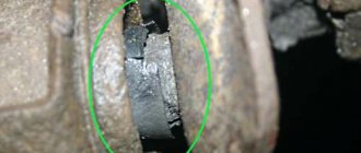
- insert the wedge you just made between the ball body and the eye;
- Hitting the rod (the base of the wedge) with a hammer, hammer in the homemade support puller until the finger pops out of the socket.
IMPORTANT!
When using this type of puller, there is always a risk of damage to the boot, so this tool can only be used in the event of a planned replacement of tips or supports. If the repair of the steering mechanism or suspension does not require such a replacement, it is better to abandon the “wedge” type puller.
Puller directly for ball joints.
Used for cars (Citroen, Peugeot) whose ball joint is screwed into the lever. And since it is screwed in and not pressed in, it is impractical to use the above tool options; you need a special puller, which we suggest you make from an 8-centimeter thick metal pipe for 2”.
- At one of the ends of this pipe, equidistant from each other, using a grinder or a hacksaw, make 4 rectangular tenons 5x7 mm.
- At the second end, using the same tool, again, cut slots equidistant from each other to a depth of 3 cm so that you end up with 8 petals.
- Use a hammer to slightly bend these petals towards the center of the circle, thereby reducing its diameter.
- Take a 24mm nut and weld it to the narrowed side of the workpiece. The DIY ball joint remover is ready.
It’s simple to use: put it on the support so that the spikes fit into the existing grooves of the ball body, then use a 24mm wrench to turn the welded nut, thereby removing the suspension element you need.
Should I change the ball joint or the entire arm?
Today I was at the service. They said that the ball joints are not good. They explained that it would not be possible to change the ball joints separately from the lever. That is, take the lever assembly. I read the fact. Some people change the balls separately, some as an assembly. Who has any opinions? Thank you!
change the ball joint. for example CNB-30. and so on . IT'S HARD TO LOOK INTO THE FAC.
Question of religion. If you add to the cost of the ball the cost of the silent rings (and the rear one is probably in the trash), and the difficulty of pressing the ball into the lever (you have to warm it up carefully, otherwise the lever will be ejected in a year), then it might be easier to change the lever.
Nissan Sunny - 1997 Nissan Bluebird Sylphy - 2001 FF2 - 2010.
Skoda Yeti. FV Tiguan.
I was in the fak. But not everything is clear to me. The mechanics say that there is no point in installing a new ball. It will not take root on the old lever. Of course, I saw a photo report on replacing the ball joint. That's why the question. It can be replaced. How long will it last? Isn't this for leverage? :-)) What do you think, good people?;-)
Oh, so I want to find out
I changed it on the previous 14th Sanka. The master pressed and pressed it hot - he heated it with a construction hairdryer. It took me 40 thousand, then I sold the car. I don’t know how much longer she lived. Now I’ll change the levers, because 120,000 for my family is cool. I just don’t know whether to install the original or a replacement - I don’t travel much.
Nissan Sunny - 1997 Nissan Bluebird Sylphy - 2001 FF2 - 2010.
Skoda Yeti. FV Tiguan.
I changed the left and right by simply pressing and pressing, without any heating. The right one stood up as if it were original, and the left one began to dangle in the lever. I took the left one for welding, and that’s how it goes. I realized that there is no point in heating it, and everything can be done this way if you are careful. I just pressed the right one a little to the side. Broke the seat in the lever. Next time you will have to change the lever. Or maybe I’ll cut off the weld and put it on it again.
I was told that heating has a bad effect on the ball itself. You can melt the plastic inside it. These are the pies. Now I’m thinking about what to do. I decided to seek advice on the forum.
Materials:
- A piece of pipe.
- The channel section is 140 mm.
- Hairpin - 12 mm.
- Nuts for stud - 2 pcs.
- Coupling for hairpin - 1 pc.
We take the pipe and end it on one side.
From a piece of channel I cut out two plugs for the pipe.
I welded a plug on one side.
I cut a piece 10 cm long from the pipe and cut out a wall in the piece.
I made a second plug from a piece of the plate and cut out a groove for the “ball pin” in it, and in the already welded plug I made a hole for the coupling.
The coupling was welded on both sides.
I cut off the excess metal to fit the shape of the pipe and scalded it.
Welded a couple of nuts.
Here is a do-it-yourself puller for ball joints, the device has been tested in use, and I am satisfied with the homemade product.
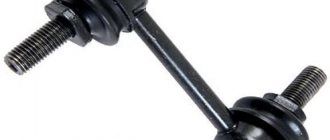
When carrying out repairs to the chassis and steering, there is almost always a need to remove ball joints or tie rod ends.
The peculiarity of these structural elements is that the support pin or tip has a conical shape, with which it fits into the seat.
During operation, the fit density increases so much that the surfaces of this joint practically stick to each other.
Additionally, moisture can get between the finger and the socket, causing pockets of corrosion that further seal the connection.
Therefore, to remove ball joints or tips, special pullers are used that allow you to press out the pin with minimal effort.
How often should the ball joint be replaced?
The frequency of replacement of joints is determined in the maintenance instructions for any vehicle. However, taking into account the “quality” of roads, supports fail much more often than the established period of 40-60 thousand km.
In addition, if the rubber boot is damaged, moisture and dirt get inside the hinge. If you don’t notice the gust in time, the unit will fail after a few hundred kilometers.
Wear is diagnosed by the presence of play and the characteristic knock of the suspension. It is recommended to regularly check the condition of the joints, especially after driving on broken asphalt or in off-road conditions.
When carrying out repairs to the chassis and steering, there is almost always a need to remove ball joints or tie rod ends.
The peculiarity of these structural elements is that the support pin or tip has a conical shape, with which it fits into the seat.
During operation, the fit density increases so much that the surfaces of this joint practically stick to each other.
Additionally, moisture can get between the finger and the socket, causing pockets of corrosion that further seal the connection.
Therefore, to remove ball joints or tips, special pullers are used that allow you to press out the pin with minimal effort.
Puller type - WEDGE
The simplest puller is the so-called “wedge”. It does not belong to any type of removable mechanism, but at the same time it is a fairly effective device for pressing out.
To make it, you only need an angle grinder (“grinder”), you can also use a machine with an abrasive wheel.
The blank will be a metal plate the size of a matchbox.
First, it is necessary to give the workpiece a wedge shape, for which we grind the metal with a grinder or machine so that the profile of the plate looks like a triangle. Then, using the same “grinder”, we make a cut in the middle 2/3 of the length of the workpiece from the side of the apex of the triangle, that is, from the thin side of the wedge. The width of the cut should be slightly larger than the thickness of the support pin, that is, you should get a kind of bracket.
If desired, you can weld a metal rod to the bracket, which will make it easier to work with the wedge in the future.
Pressing out a finger with a wedge is very simple. It is installed in the gap between the eye and the support body. And then the wedge is simply driven in with a hammer, which leads to the finger popping out of the socket.
The disadvantage of the wedge is that the boot will be damaged during the pressing process. Therefore, the wedge can only be used when replacing supports or tips.
If the suspension and steering mechanism are being repaired, which does not involve replacing the ball elements, it is better not to use a wedge.
Lever puller
Unlike a screw, the fixture uses both the force of the thread and the lever.
The operating principle is visible in the illustration:
The lever arm relative to the hinge axis increases the force on the thread at least twice. The ball pin breaks off more evenly. Thanks to the offset hexagon, the suspension elements will not interfere with the wrench handle when tightening the bolt.
Screw release mechanism
The second type of removable mechanism, which can be made from improvised means, is a screw release mechanism. It is perfect for replacing ball joints of classic VAZ models.
A special feature of the suspension design of these cars is that the upper and lower supports are located symmetrically to each other and the distance between them is not large.
It can be made at home only if you have a drilling machine, or you will have to go to a lathe. This puller consists of only two parts.
To make it, you will need a square or hexagonal rod with 17 or 19 key edges, the length of which is 7 cm. Using a drilling machine, we make a hole in this rod and cut a thread for a bolt of 8. Screw in the bolt and that’s it - the puller is ready.
Let's look at how it works using the VAZ-2107 as an example. To press out the upper support, you need to unscrew the lock nut, but not completely, you do not need to remove it. Then we install the manufactured puller between the pins of the supports with the bolt screwed in until it stops.
To squeeze out the finger, we take two keys - with one we hold the manufactured body, and with the second we unscrew the bolt until the finger falls off the socket. After replacing the upper support, we do the same, but with the lower one.
Types of pullers
The auto tools market offers a wide selection of such removable mechanisms, which can be divided into two types:
- Screw;
- Lever.
Screw pullers are considered universal and are suitable for working with almost any car.
The force in them is created by screwing the bolt into the puller body. The housing itself is put on the support eye, and when tightened, the bolt rests against the support pin and presses it out of the socket.
Lever removable mechanisms are no less effective, but they are larger in size, so they may not be suitable for every car.
For example, with such a puller on a VAZ-2107 you can still remove the upper ball joint, but you won’t be able to get to the lower one due to very limited space.
For these purposes, a special puller is used.
The essence of a lever puller comes down to the presence of two levers connected in the middle.
On the one hand, holes are made in them and a coupling bolt is installed.
To press out, one lever is installed between the eye and the support, while the second lever is placed under the finger.
When the bolt is unscrewed, due to the existing connecting axis, the ends of the levers begin to converge and the pin is pushed out.
But it is not necessary to purchase a removable mechanism; it can easily be made at home from improvised materials.
Next, we’ll look at several types of ball joint and steering wheel pullers that you can make yourself.
Screw L-shaped
The third type of removable mechanism, which you can make yourself, is also a screw mechanism, but it has shown itself to be excellent and allows you to work on any car.
To make it you will need a round metal rod with a diameter of at least 10 mm and a length of 15-17 cm.
From it you need to make an L-shaped blank with a shoulder length of 5 cm. That is, we take a rod, measure 5 cm on it, clamp it in a vice and use a hammer to bend it 90 degrees.
We cut a thread on the long part of the workpiece and select a nut.
All that remains is to make the thrust bar. It can be made in the likeness of the wedge described above. That is, we take a plate, but 0.5 cm thick. On one side we make a cut for the support pin.
Screw made from angle
Another screw puller can be made from a metal angle and a welding machine.
To do this, take a corner with sides 7-8 cm and the same length, and a thickness of 0.3-0.5 cm.
We make a cut in one of the sides to secure the mechanism to the eye. From sheet metal 0.3 cm thick we cut out two triangles that will act as braces. They need to be welded on the sides to the corner. This will significantly increase the strength of the structure.
We take a 17 nut and a long bolt for it. We weld the nut itself perpendicular to the cut so that its hole faces the cut.
So that in the future the bolt can be easily positioned on the same axis with the pin, before securing the nut by welding, a spacer must first be welded onto the corner.
All that remains is to screw in the bolt and the puller can be used.
These are the simplest types of removable mechanisms that you can make yourself.
In general, there are a lot of options, and with a little imagination and basic knowledge of plumbing, you can easily come up with and make your own puller.
We offer some drawings for viewing.
Tool for unscrewing the support
We will consider another type, which is used not for pressing out the finger, but for removing the support itself.
The fact is that on a number of cars (Peugeot, Citroen) the ball joint is screwed into the lever. Over time, the threaded connection sours, and it is quite difficult to unscrew this suspension element without a special tool.
But you can make the necessary puller yourself, rather than spending money on a factory one.
It is made from a 2" thick-walled pipe 8-9 cm long.
At the end of this pipe it is necessary to make 4 spikes with a width of 5 mm and a height of 7 mm, located at an angle of 90 degrees relative to each other.
That is, you should get 4 protrusions at the end of the pipe, evenly distributed around the circumference. This can be done using a hacksaw and a file, or with a grinder.
From the other end we make slits to a depth of 3 cm, dividing the circumference of the pipe into 8 parts.
Then we bend these petals to the center using a hammer, significantly reducing the diameter.
We take a 24mm nut and screw it to the end part, and then use a welding machine to seal the slots made.
It is quite convenient to work with such a puller - we put it on the support so that the spikes fit into special grooves on the support body.
In this case, the finger will pass through the manufactured tool, which will allow the locking nut to be screwed onto it, thereby securing the puller. All that remains is to use a 24mm wrench to unscrew the support using the welded nut.
DIY ball joint replacement
Depending on the make of the car, the sequence and types of work may differ. Consider the most common cases:
The support is pressed into the suspension arm or bolted
First of all, don’t forget about safety: handbrake, gear, wheel chocks. Use a wheel wrench to remove the wheel bolts or nuts. We lift the car with a jack. We place the racks or spare wheel under the threshold. Unscrew the wheel fasteners and remove the wheel. Using a metal brush, we clean the fasteners of the ball joint and the bolts of the silent blocks of the suspension arm. We process it with “Liquid Key”. We wait 10-15 minutes.
Treatment of silent block fastenings with “Liquid wrench”
Unscrew the nut securing the ball joint to the steering knuckle. If space allows, we use a head and a wrench. If not, we use the cap side of the key so as not to tear off the edges. The nut is tightened sufficiently tight.
If you have a special puller, remove the ball joint pin from the eye. We place the U-shaped part of the puller under the eye of the fist above the support boot. Use a wrench to tighten the puller nut and press the L-shaped part onto the ball pin.
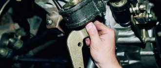
The process of removing the ball joint along with the suspension arm from the steering knuckle
If there is no puller, use the pry bar as a lever. We insert it between the suspension arm and the axle shaft, pressing down to create tension in the assembly. We knock with a hammer on the place where the ball joint with the steering knuckle is attached. The tension and shock must be strong enough. The finger should pop out.
If it is fixed with a locking bolt, unscrew the nut and remove it. If necessary, we help ourselves with a hammer. In order not to spoil the thread, tighten the nut and knock on it.
Unscrew the bolts securing the suspension arm to the subframe. If the nuts on the reverse side turn, hold them with a wrench. We take out the bolts. The bolt of the longitudinal silent block may rest against the axle shaft. In this case, we use improvised stands for the steering knuckle. We raise it to a height that allows us to reach the bolt. We remove the lever.
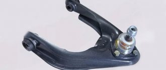
The process of removing the suspension arm (together with the ball joint) from the subframe
If the ball joint is attached to the suspension arm with bolts, then unscrew them. The factory support may be attached with rivets. In this case, drill them out. To fasten the new part we use purchased bolts.
If the ball joint is pressed in, then remove the retaining ring (you can also remove the boot if it gets in the way) from the pin side. It is enough to pry them off with a flat screwdriver.
Removing the retaining ring and boot from the ball joint
Using a special puller, we press out the support. If there is no such thing, we knock it out with a hammer. The heavier the hammer, the easier it is. For convenience, we clamp the lever in a vice, or place it on two bricks so that nothing interferes with the exit of the ball. For accentuated blows with a hammer, we use a ball pin attachment. The ½ extension cord from the tool kit is perfect for these purposes. The ball pin can be cut with a grinder, which will make knocking it out easier. Since the force of the impact will not be absorbed by the unfixed finger, but will be absorbed by the body. If the support does not give in, we try to heat it with a gas burner. The metal will expand, which should help.
Pressing the ball joint out of the lever
Pressing is carried out in the following sequence. We treat the seat with liquid key. After drying, lubricate with soapy water. Don’t forget to lubricate the support for better sliding (unless the new ball is already lubricated by the manufacturer). In the absence of special tool for pressing, select a mandrel suitable for the diameter. This could be a bearing race or a head from a tool kit. When pressing using improvised means, you must not strike the center of the new support . The load should be distributed evenly along the edges of the ball. We avoid distortions. Using light blows in a circle, we drive the part into the seat.
Pressing in the ball joint
On the side of the ball pin, we put on the boot, if we removed it from the new ball, and the retaining ring, helping with a flat screwdriver. It is important to act carefully so as not to tear the boot. An indicator that the retaining ring is in its place is free rotation along the ball. Installation of the lever is carried out in reverse order.
You can watch the video for more information about replacing the ball joint:
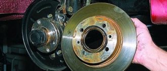
The support is pressed into the steering knuckle
With the car assembled, unscrew the central hub nut. This may require a special head and driver that can withstand heavy loads. To make your task easier, you can put a pipe of a suitable diameter on the knob.
Removing the center hub nut
If your car has alloy wheels without a center hole, we start by removing the wheel. We take all precautions. We hang out the problem side and remove the wheel. Unscrew the hub nut. To fix the hub, ask your partner to press the brake pedal. If the brake discs are ventilated, insert a powerful screwdriver into the central air channel and press it against the caliper, thereby locking the hub. This will allow you to perform this operation yourself.
Unscrew the ABS cable mount and the sensor itself from the steering knuckle. Unscrew the brake hose fastener. Unscrew the caliper guide bolts. We insert a flat-head screwdriver into the inspection window of the caliper between the brake disc and the pads, and separate them. We remove the caliper. We tie it with a rope or wire to the spring - do not leave it hanging on the brake hose. The ABS sensor can be hung in the same way.
Disconnecting ABS and caliper
Unscrew the nut securing the upper ball joint with the steering knuckle and the lower support with the suspension arm. Unscrew the nut securing the steering end with the steering knuckle and unscrew it. The cotter pin gives in quite easily; if necessary, we help ourselves with pliers. We remove the pins of the ball joints and the steering end from the eyes using a puller or a hammer, similar to the first case.
The process of knocking out the ball joint rod from the steering knuckle seat
We take out the steering knuckle. We change the support to a new one by analogy with point No. 1. Installation of the steering knuckle is carried out in the reverse order.
Removing the old and pressing in the new ball joint
You can find out more about this option in the video:
Alternative method
Finally, we note that it is possible to press out the support pin or tip even if it is not possible to make a removable mechanism. But this method should be used only in extreme cases. To remove the finger you will need a pry bar and a hammer.
The pry bar is used as a lever and must be installed in such a way as to create a force to press the support or tip, for example, place it between the steering rod and the rack eye.
After creating force with the mount, it is necessary to apply powerful blows to the body of the eye with a hammer. If everything is done correctly, then after 2-3 hits the finger will pop out.
The disadvantage of this method is that the eye can be damaged due to shock loads, so it is advisable to use pullers rather than knock out the support.
Features of dismantling
No matter how good a tool you have in your hands, you need to use it correctly. Otherwise, there will be no sense. It is important to properly prepare the lever for repair. During operation, the connection between the steering knuckle and the steering pin is exposed to chemicals found on the road. Also, dust and sand get into the threaded connection. All this leads to sticking of parts. To avoid the hassle of disassembling them, you need to clean them before work.
Read more: Chevrolet Aveo hatchback automatic owner reviews
This is done with a metal brush. After cleaning off the dirt, the joint is generously moistened with penetrating lubricant. These actions must be carried out several hours before repair, so that the lubricant eats away a sufficient amount of rust.
Conclusion
. There are a large number of devices available for complete car repairs. They all make the job easier. At the same time, drivers often wonder how to make a steering wheel end remover with their own hands. After all, the options sold in the store are not very reliable, which makes repairs a lottery; the risk of breaking the instrument is quite high.
When carrying out repairs to the chassis and steering, there is almost always a need to remove ball joints or tie rod ends.
The peculiarity of these structural elements is that the support pin or tip has a conical shape, with which it fits into the seat.
During operation, the fit density increases so much that the surfaces of this joint practically stick to each other.
Additionally, moisture can get between the finger and the socket, causing pockets of corrosion that further seal the connection.
Therefore, to remove ball joints or tips, special pullers are used that allow you to press out the pin with minimal effort.