Removing and installing the gearshift lever on a VAZ 2107
When driving a car, the VAZ 2107 gear shift lever is needed in order to be able to vary the speed using the gearbox.
Like any part of a car, it is susceptible to malfunctions, so this article is about how to remove the gearbox lever of a VAZ 2107 and, if necessary, repair or replace it. The lever itself is a short segment coming out of the switching mechanism (in everyday life a rocker), and its continuation with a knob is called a rod. If it loosens too much, it can lead to difficult gear shifting or it may simply fly off the lever. Such consequences usually result when gear shifting is difficult for some reason, or the damper spacer sleeve has simply become loose over time, or the problem is in the rocker.
Main differences from LADA 2105 [edit | edit code ]
- A more powerful engine with a volume of 1.5 liters and a power of 77 hp. With. (for carburetor versions);
- A modified, often chrome-plated radiator grille with a larger area (in the last years of production, the LADA-2104 was equipped with the same ones for unification purposes)
- The structure of the rear lights has been slightly changed (5-section instead of 6-section in 2105);
- More comfortable front seats with integrated headrests (in the last years of production, the LADA-2105, 2104 were equipped with the same ones for unification purposes);
- Some of the cars produced were equipped with a rigidly molded interior headliner and plastic ventilation linings for the rear pillars;
- Modernized front instrument panel (in particular, a tachometer and speedometer with digitization up to 180 km/h were added, as well as an oil pressure indicator (until 1988, after which it was replaced by an econometer;
- Added cold air deflectors (“torpedo”) located in the center. While a stream of hot air can be directed into the legs (through the interior heater), through these deflectors a stream of cold air can be directed into the face (only at speed, with the pressure of the oncoming air flow);
- Plastic bumpers with chrome plates instead of more massive aluminum ones (in the last years of production on LADA-2105, 2104, for the purpose of unification and reduction in cost, the same ones were installed);
- Changed shape of the hood (in the last years of production, the LADA-2104 was equipped with the same ones for unification purposes);
- Slightly changed shape of the trunk lid (without stampings), since 2008 they began to install a trunk lid with stampings, like the VAZ-2105, due to the unification of production;
- Some interior details have been changed: door upholstery, door lock buttons, radio panel (“beard”), gearshift knob, steering wheel shape (which later became uniform due to unification);
- The electrical system circuit differs (there are also differences between individual modifications depending on the type of engine).
How to dismantle the gearbox lever of a VAZ 2107
If you had problems with play in the bushings, then you need to purchase a repair kit for the VAZ 2107 gearbox handle in advance and after dismantling it.
Before starting work, prepare a screwdriver.
- Set the box to neutral.
- Slide the cover.
- Push the damper locking sleeve down with a screwdriver.
- Remove the rod with the knob.
- Remove the remaining bushings from it.
- Replace them in reverse order as shown in the picture.
Before reinstalling, fully assemble the rod and bushings, slide it onto the lever, and push down sharply to seat it in place.
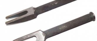
If you need to completely replace the rocker, then add a 10mm wrench to the screwdriver (preferably a socket or socket):
- remove the decorative panel;
- unscrew the boot;
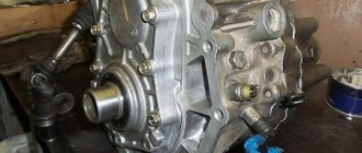
- use a 10mm key to unscrew the mechanism;
- remove it from the box.
After repair or replacement, assembly is performed in the reverse order.
The quality of bushing repair kits leaves much to be desired and the backlash of the rod remains quite large, so some, instead of plastic and rubber bushings, simply select a simple hose according to size and attach it to it.
Removing a carburetor engine with disassembly
1. Place the car on an inspection hole or overpass (see “Preparing the car for maintenance and repair”).
5. Disconnect the fuel supply hose to the fuel pump (see “Fuel pump - removal and installation”).
6. Disconnect the wire tip from the oil pressure sensor (see “Oil pressure sensor - replacement”).
11. Disconnect the coolant drain hose from the heater radiator pipe (see “Heater radiator - replacement”).
13. Having disconnected the wires, remove the starter from the engine compartment (see “Starter - removal and installation”).
14. Unscrew the nuts of the lower fastening of the front supports of the power unit to the cross member (see “Power unit supports - replacement”).
15. We hang the cylinder block from a wooden beam, placing it on the front fenders of the car. We place a soft cloth under the beam.
16. Raise the block and, removing the support studs from the holes in the cross member, remove it from the engine compartment.
Lever tuning
The gear lever is located on the “seven” somewhat poorly, some believe that it is too long, others stretch far, and a general remark when turning on the reverse gear is added to the main ones, that we hit our hand on the passenger’s knee.
Some select levers from foreign cars that are suitable in size and secure them. The second, and easiest, thing to do when upgrading the handle yourself is to simply make it shorter. To do this, the lever rod is sawed off to 5 - 7 cm in length and the thread is re-cut.
The most radical way of tuning is to move the lever closer to the driver and reduce its travel when changing gears. It looks, when brought to its logical conclusion, solidly.
Read more about this procedure on the website.
The above tuning of the lever makes the interior of your car unique, but do not forget about driving safety because the given examples have their pros and cons, and it’s up to you to decide whether to do them or not.
DIY repair instructions for the VAZ 2107 5 mortar gearbox
The design of the gearbox of classic domestic cars suffers from low reliability and inability to withstand high loads. Repairing a VAZ 2107 5-speed gearbox is a rather complex procedure that requires a responsible approach and extensive experience. However, if you know the procedure and are technically trained, you can perform the maintenance yourself. As a rule, cars begin to have problems with the inclusion/deceleration of speeds and the loosening of the rocker. With such symptoms, surgical intervention in the structure will be required.
Rules for disassembling and assembling the gearbox
- Disassembly of the mechanism is carried out only after it has been completely cleaned of dirt.
- All the tools required for disassembly are pre-prepared - keys, squeezes, pliers, lock ring pullers. It is also advisable to have a separate container for storing small bolts, nuts, and washers.
- It is necessary to dismantle the mechanism parts by first treating the bolts with an anti-boiling agent.
- When disassembling, the units are folded in the dismantling sequence.
- Human memory is extremely unreliable - a photograph of a disassembled mechanism before its reassembly is the best reminder.
- All gaskets without exception must be replaced. Recycling of seals is strictly prohibited.
- No one has canceled the abundance of the cleaner. When washing the structure, you should not skimp on the cleaning material; the better you wash it, the more fun it will be.
- Assembly of the unit is carried out exclusively in the reverse order.
- If after installation there are excess parts left (which is not uncommon), the entire gearbox is completely rebuilt.
It is also necessary to maintain maximum cleanliness during work. Dust, metal shavings, or foreign objects can cause serious damage to the gears.
Removing and installing the engine
There are two options for removing the engine from a car: with engine disassembly and without engine disassembly. Removing the engine from the vehicle and disassembling it is recommended if there are no mechanical or hydraulic devices for lifting the engine (a hoist with a traverse, a “goose”, etc.). It is recommended to carry out engine removal work with one or two assistants.
Removing the engine without disassembling
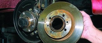
Place the car on a lift or over an inspection ditch, place supports under the front wheels and hang the rear axle on one or both sides.
Remove the hood, disconnect the wires from the battery and from electrical components installed on the engine. Remove the battery and engine compartment lamp.
Drain the liquid from the radiator, cylinder block and heater by unscrewing the plugs on the left side of the cylinder block and on the lower radiator tank, move the upper heater control lever to the right (it opens the heater valve) and remove the plugs from the expansion tank and radiator.
ATTENTION : To avoid damaging the radiator, when unscrewing the drain plug, hold the plug fitting soldered into the radiator with a second wrench. Unscrew the plug with a socket or socket wrench so as not to tear off the edges of the plug.
Disconnect the coolant inlet and outlet hoses from the engine and remove the radiator along with the thermostat, hoses and fan motor.
Remove the air filter by first disconnecting the hoses from it, removing the cover and filter element. Close the carburetor with a technological plug.
Using a spanner, unscrew the nuts securing the front muffler pipe to the exhaust manifold.
Remove the gearbox as described in the "Gearbox" chapter.
Disconnect the carburetor throttle linkage and the choke control cable from the engine. Disconnect the fuel supply hose and the hoses going to the heater from the engine.
Hang the TSO-3/379 traverse on the hoist and sling the engine on the right side through the bracket installed on the front stud of the exhaust manifold, and on the left side - behind the clutch cover mounting hole.
Engine mount
1 — support casing; 2 — front engine mount support; 3 — cylinder block flange; 4 - bracket; 5 — intermediate plate; 6 - insulating plastic ring; 7 — support spring; 8 - buffer; 9 — support cushion; 10 — washer; 11 — rear engine mount support; 12 — spacer sleeve; 13 — cross member of the rear engine mount
Lightly tension the hoist chain, unscrew the nuts securing the mountings 9 of the front engine mount to the cross member of the front suspension and remove the engine from the compartment.
Remove the starter heat shield, starter and hot air intake along with the supply hose. Remove the two side brackets with the front engine mount cushions from the cylinder block.
Unscrew the clutch mounting bolts and remove it.
Install the engine on the car in the reverse order of removal. Pay special attention to the connection between the engine and the gearbox: the input shaft must fit exactly into the splines of the clutch driven disc.
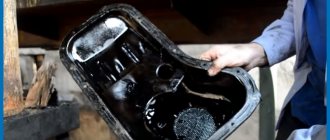
Wash the engine in a washing machine, place it on a disassembly stand and drain the oil from the crankcase.
Remove the carburetor by disconnecting the hoses and throttle linkage from it.
Remove the fuel pump, ignition distributor, use wrench 67.7812.9514 to unscrew the spark plugs and coolant temperature gauge sensor.
Remove the generator and coolant pump drive belt, remove the generator and generator bracket.
Removing the engine from the car with disassembly
- We install the car on an inspection hole or overpass
- Removing the mudguard
- Removing the hood from the car
- Removing the battery
- Disconnect the fuel supply hose to the fuel pump
- Disconnect the wire tip from the oil pressure sensor
- Removing the radiator from the car
- Removing the thermostat
- Removing the generator
- Remove the cylinder head from the engine
- Disconnect the coolant drain hose from the heater radiator pipe
- Removing the engine flywheel
- After disconnecting the wires, remove the starter from the engine compartment of the car.
- We unscrew the nuts of the lower fastening of the front engine mounts to the cross member
- We hang the engine cylinder block from a wooden beam, placing it on the front fenders of the car. Place a soft cloth under the beam
- We lift the cylinder block and, removing the support studs from the holes of the cross member, remove the engine from the engine compartment of the car
Installing the engine on a car
Assembling and installing the car engine is performed in reverse order.
Instructions for disassembling the VAZ 2107 gearbox
The VAZ five-speed gearbox is disassembled in this way.
- Drain the lubricant from the mechanism housing.
- Remove the structure from the machine.
- Remove the release bearing clutch and clutch release fork.
- Disconnect the elastic insert of the propeller shaft.
- Remove the coupling flange from the gearbox output shaft.
- Disconnect the engine mount (mount), speedometer cable, reversing light wiring (if equipped).
- Dismantle the cuff of the ball joint of the lever, using an open-end wrench No. 10, unscrew the 3 nuts securing the lever to the crankcase cover.
- Remove the lever housing from the stud bolts and gasket.
- Unscrew the nuts of the exhaust pipe bracket with a size 13 wrench.
- Remove the part and remove the mounting bolt.
- Clean the surface of the gearbox from dirt and oil stains with alcohol or solvent.
- Remove the back cover with gasket.
- When unscrewing the nuts with hairpin bolts, the parts are screwed in as is when a special compound is applied.
- Also, use the 13th key to remove the last nut of the rear cover inside the crankcase compartment.
- Press in the shift rod for 1st and 2nd gears.
- Remove the compartment cover from the crankcase.
- Remove the rear wall from the stud bolts and, turning clockwise, completely dismantle the part.
- Remove the plastic plug from the gear box 5 and reverse gear using a hammer.
- Using tweezers, remove the retaining ring of bearing 5 and reverse gear.
- Press out the bearing with a spacer using a hammer or a special press.
- It is convenient to remove the secondary shaft seal by picking it up with a sharp object.
- Remove the thrust disc of the inner ring of the second bearing.
- Press out the part by analogy with the first one.
- Tie the completely disassembled unit with wire to prevent loss.
- Remove the speedometer drive and oil deflector.
- Using wrench No. 10, unscrew the fasteners of the power fork for the fifth and rear positions of the block.
- Use socket No. 17 to loosen the fastenings of gears 5 and R positions.
- Use head No. 13 to unscrew the first clutch nut and No. 17 to remove all other nuts.
- Remove the clutch disc housing.
- Using a press or drift, knock out the drive shaft oil seal. Remove the seal from the front cover of the unit.
- Remove the spring from its socket (put it back with the narrowing towards the bearing).
- Using head No. 19, unscrew the intermediate pipe bearing fastening, then remove the bolt along with all the fallen parts.
- Using a 17 key, remove the gear block fastening.
- Remove the gears from the intermediate pipe.
- Clamp the block in a yew and press the inner bearing insert from it.
- Remove the spacer washer.
- Unscrew the hatch of the rod clamps and remove it.
- Remove the rod springs and retaining balls.
- Remove the fifth gear gear with synchronizer clutch.
- Remove the spacer ring.
Assembly
Assemble the cardan shafts in the reverse order of disassembly, taking into account the following instructions:
— apply FIOL-1 lubricant to the spline connections;
— when connecting parts, align the marks placed on the detachable parts before disassembly;
— after assembling the spline connection, pressing the oil seal by 0.3–0.5 mm with an axial load, crimp the clip onto the groove of the fork;
— tighten the nut securing the front propeller shaft fork with a torque wrench and caulk it.
| Rice. 4–47. Pressing the bearing into the elastic support: 1 - mandrel A.70045; 2 - bearing; 3 - elastic support |
When assembling the intermediate support, press in the bearing using mandrel A.70045 () and install a retaining ring in the groove of the support.
| Rice. 4–48. Details of the front propeller shaft: 1 - elastic coupling; 2 — centering sleeve; 3 — elastic coupling flange; 4 - oil seal; 5 — oil seal cage; 6 — cardan shaft; 7 — dust deflector; 8 — bearing; 9 — retaining ring; 10 - nut; 11 — universal joint fork; 12 — dust deflector; 13 - elastic support |
| Rice. 4–49. Installing an elastic support on the front driveshaft: 1 - mandrel A.74035; 2 - elastic support; 3 - rear part of the front driveshaft |
Place dust deflector 7 () on the rear end of the front propeller shaft; then, using mandrel A.74035 (), press in the support with the bearing and put on the second dust deflector 12 (see), press the fork 11 of the front propeller shaft onto the shaft and secure it with a nut, as indicated above.
Assemble the universal joint (old design) in the following order.
After removing the old thickened grease, fill the cavities in the spider spikes and lubricate the inner surface of the bearing housings with FIOL-2U grease (0.4–0.6 g for each bearing). Lubricate the spikes of the cross with a thin layer of lubricant to prevent the formation of an air cushion during assembly. Insert the spider tenons into the fork.
Place the bearing housings with needles on the spider spikes and press them into the fork holes with a force of 7840 N (800 kgf). Install the retaining rings in the grooves of the fork in their original places according to the marks. Then check the axial free play of the spider, which should be 0.01–0.04 mm. If the free play is greater than specified, replace one thinner snap ring with a thicker one.
| Rice. 4–50. Cardan joint assembly: 1 — cardan joint fork; 2 - retaining ring; 3 - bearing housing; 4 - oil seal; 5 – spike of the cross; 6 — bearing needle; 7 — dipstick; A, B, C, D - probe petals having a thickness of 1.53; 1.56; 1.59; 1.62 mm |
In the case of replacing parts of the cardan joint, the selection of retaining rings by thickness is carried out with caliber 41.8734.4092, which has four petals in thickness: 1.53; 1.56; 1.59; 1.62 mm. To do this, install a locking ring 2 () with a thickness of 1.56 mm. When pressing bearings, when the cross rests against the bearing housing (in this case there are no gaps), use caliber 41.8734.4092 to determine the distance between the bearing housing and the end of the annular groove. Depending on the measured distance, taking into account the axial clearance of 0.01–0.04 mm, insert a second circlip of appropriate thickness.
| NOTE Retaining rings are supplied in spare parts in five (seven)* sizes (thickness, mm), each of which has a specific color: 1.50 (1.45)* - natural; 1.53 (1.52)* - dark brown; 1.56 (1.56)* - blue; 1.59 (1.60)* - black; 1.62 (1.48)* - yellow; (1.64; 1.67)* - colors are not indicated and their thickness is determined by measurement. * For a new hinge design. |
For example, if a 1.56 mm petal passes, then a 1.53 mm ring should be installed. If the measuring probe of the smallest thickness (1.53 mm) does not fit into the groove, then replace ring 2 with another one - 1.50 mm. If the measuring probe of the greatest thickness (1.62 mm) fits into the groove with a gap, then replace ring 2 with another one 1.62 mm thick.
After installing the retaining rings, hit the bearings with a hammer with a plastic striker. Under the influence of impact and elastically compressed oil seals, the gap between the bottom of the bearing and the retaining ring is selected and gaps appear between the bearing housings and the ends of the crosspiece studs. After assembly, check the ease of rotation of the hinge forks and the balancing of the cardan drive.
The assembly of a universal joint with stamped needle bearing housings has its own characteristics:
— the gap between the bearing housing and the end of the annular groove is measured using two gauges, one of which has a set of feeler blades with a thickness of 1.45; 1.48; 1.52; 1.56 mm, and the other - 1.60; 1.64; 1.67 mm;
- if the petal of the feeler gauge of the smallest thickness (1.45 mm) does not fit into the gap between the bearing housing and the end of the annular groove, then replace ring 2 (see) with a thickness of 1.56 mm with another one with a thickness of 1.45 mm. Then repeat the operations;
- if the petal of the greatest thickness (1.67 mm) does not fit into the gap tightly, then install a ring 1.67 mm thick into this gap, remove the previously installed ring (1.56 mm) and repeat the operations for selecting the thickness of the ring until you achieve a tight fit entry of the feeler blade into the gap between the bearing housing and the end of the groove.
Repair of VAZ 2107 5-mortar gearbox
The above procedure involves complete disassembly of the unit as a preventative measure. However, it happens that the manual transmission unit knocks out or slips during driver manipulations. Moreover, the VAZ five-speed transmission suffers from such things all the time. The reason for the repair may be one of the following factors:
For a more accurate understanding of the process, you can watch video master classes of the process from experienced specialists.
4th gear slips out
On a five-speed VAZ 2107 gearbox, fifth speed overshoot can provoke wear of the gear, synchronizer, and related parts.
During the repair, the 3/4 clutch, the damaged element and a complete set of seals that are subject to separation during disassembly are replaced.
Note! Some mechanics claim that in 40% of cases, replacing the driveshaft mount and clutch fork saves the day.
5th gear slips out
The five-speed gearbox of the “seven” periodically gives out vagaries to the user due to insufficient gear lubrication. It is recommended that in case of knockout or tight engagement of a position, completely change the synchronizers, gear, fork and bushings - this will ensure stable operation of the unit.
Note! Before purchasing spare parts, it is necessary to troubleshoot them. Some stores sell "crooked" parts.
Repair of gearbox lever (backstage) VAZ 2107
If the gearbox linkage (handle) becomes loose, repairs can be carried out even without removing the unit from the car. However, some experts recommend using “garage” repair parts. For the convenience of the reader and a clearer explanation of the process, it is better to complete the description in pictures.
- Dismantle the cover and remove the locking bar from the rocker bushing.
After release, the lever axis is removed; for convenience, you can push the insert with a screwdriver or a pusher.
Usually the bushing itself wears out; you can replace it with a new insert or a standard M10 bolt.
Next, fasten everything in the reverse order and tighten the structure.
Old-style VAZ 2107 gearbox repair
Before repairing an old-type VAZ gearbox, it is advisable to study the user manual or technical documentation. The main nuance is the absence of 5th gear - the classic system has only 4 positions. Therefore, the reverse gear is located separately. This should be taken into account during repairs.
Repair of VAZ 2107 transmission without removing the box
In case of emergency, you can repair the VAZ 5th transmission without removing the housing from the car. When performing the procedure, the car is driven onto an overpass or inspection hole. All manipulations are performed upside down, which complicates the process. Therefore, experienced auto mechanics prefer to first dismantle the unit from the car.
Self-replacement of the VAZ 2107 gearshift lever
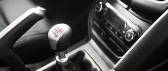
The VAZ 2107 gear shift lever is used to enable the driver to control the car, which is possible using a gearbox. The gearbox, in turn, is a mechanism inside which there are gears of different diameters. This device is the link between the engine and the drive wheels of the car. For rear-wheel drive cars, which is the VAZ 2107, the manual transmission is typically located under the lever itself. To connect the lever to the gearbox, no additional link is required, as is typical for front-wheel drive car models. The VAZ 2107 rocker is presented in the form of a small half-bent tube onto which the gearshift lever itself is placed. In the material we will pay attention to the question of how to replace it, as well as the features of dismantling.
Device location and characteristics
The gearshift lever of the VAZ 2107 is located directly in the car's interior. It is used to be able to change gears while moving. The gear lever fails only in rare cases, and the reason for this is negligence towards the product. If the product fails, it must be replaced. But before replacing, it is necessary to remove the product in question. We’ll find out in more detail how to remove it, as well as replace it on the “seven”.
On the “seven” the gear shift knob has a common problem - rattling and chattering. If you fix such a malfunction using improvised means, then replacing the device will not be necessary. Before you begin replacing the device, you will need to find out the exact causes of the malfunction. After all, sometimes not only the part in question can “fail,” but also the gearbox or clutch.
If you are convinced that it is the gearshift lever that is faulty, then only then should you start replacing it.
Replacement features
Before you begin the replacement, you need to stock up on tools such as wrenches and a screwdriver. We start with the following steps:
- Set the lever to neutral position.
- After this, you need to slide the top cover up. There is no need to completely remove the cover.
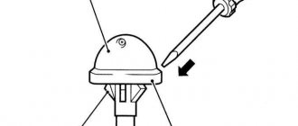
- The next step is to move the cover, which is located below, to the top. This cover is also called a thermal protection valve. In the photo below it is shown with a red arrow.
- Now you need to press the device, pushing it to the bottom. After this, you need to insert a screwdriver into the lower part of the product, where the plastic sleeve is located. The bushing is located at the very bottom of the device, as shown in the photo below.
- It is necessary to move the locking sleeve to the lower part, and then remove the product from the box.
- If the device emits strong vibrations, it needs to be replaced with a new one. In this case, you can exchange the part for a product of shorter length, as on foreign cars. A short device is much more comfortable to operate than a standard product.
Many motorists replace the standard gear shift levers with more modern ones, which allows them to uniquely customize the interior of the Seven.
After the standard product is dismantled, we install a new handle in its place. Let's look at what the installation is.
Installing the device on a VAZ 2107
After the standard mechanism has been removed, you will need to remove the rubber bushing from it, if it remains inside. To remove the bushing, you need to use a screwdriver or hook. By prying the sleeve, we remove it from the device, as shown in the photo above.
If you plan to install a standard product in place, then it is advisable to replace the bushing by purchasing a repair kit in advance. When choosing a repair kit, preference should be given to products manufactured by VAZ. The installation process is similar to removing the device. Initially, a rubber bushing is installed, recessing it into the device. Following the bushing, it is necessary to install a rubber band in the form of a washer, which softens the control of the mechanism. Next, you need to install a plastic lock inside the mechanism, due to which the device is fixed to the gearbox “scene”. The assembly is completed by installing the locking sleeve, which had to be moved down at the initial stage in order to dismantle the gearbox lever.
Once the product is ready for installation, you will need to insert it into the drawstring. To do this, you should initially lubricate the slide, and then hit the mechanism handle well with your hand until you feel that the lever has settled into place. This is how the installation of both new and old mechanisms, which were dismantled to replace component parts, is carried out.
Self-tuning of the handle
Some drivers are not satisfied with the quality of repair kits for installation, and they came up with a kind of tuning of the gearbox handle itself: to reduce rattling and vibration going to the shift handle, instead of standard plastic bushings and rubber bands, they insert a piece of hose that fits the outer and inner diameters. This upgrade also allows for easier future installation of the handle.
Additionally, you can make the gear shifting process more convenient by slightly reducing the length of the standard handle. To do this, you need to remove the lever, cut it with a hacksaw to 5-6 cm in length and cut a thread at the end, the same as it was on the cut piece (if you wish, you don’t have to cut the thread). These upgrades are advisory in nature and have their pros and cons. Each driver decides for himself whether to produce them or not.
When choosing products for foreign cars, you should make sure that it can be reliably installed on the VAZ-2107. Otherwise, an incorrectly secured mechanism will lead to an emergency situation while driving.
How to Remove a VAZ 2106 Engine
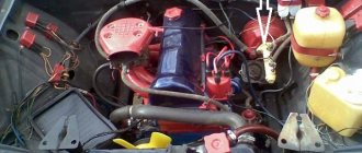
To remove and install the engine on a VAZ 2103, we need wrenches for “10”, “13”, “17”, “19”, we also need two screwdrivers, a special clutch for the central clutch disc, pliers, a strong rope and a lift. to raise the motor. If this is all, we proceed to remove the engine from the car for this purpose: Turn off our car, remove the battery. The hood also bothers us because it needs to be fixed (body repair). The previously prepared container must be drained of all coolant. We also get rid of the engine that will get in our way.
Next, it is enough to formalize: The starter must be removed. Also remove the radiator. Disconnect the intake manifold from the vehicle's exhaust manifold. Disconnect the box with it, disconnect the clamping device from the pusher.
Remove the engine compartment lamp by disconnecting the wire and unscrewing the mounting nut. Remove the carburetor air filter, after removing it, clean the carburetor with a clean cloth, in other words, a service plug, after disconnecting the wire from the electric valve, and you need to disconnect the throttle and choke control rods. Release the clamp and remove the vacuum hose. Unscrew the mounting brackets and remove the heater hoses, and remove the thermostat bypass hoses and radiator inlet hose. Then remove the thermostat with the antifreeze hoses to the pump. Remove the wide hose.
Assembly of the VAZ 2107 five-speed gearbox
Five-speed gearboxes of the classic design since 2004 or after 2004 have received a number of changes and are slightly different from the previous ones.
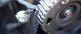
This is how teeth should be. Spicy from top to bottom!
New fork, clutch and gears with 3rd gear synchronizer.
Fork and clutch for 5th gear and reverse gear. Also completely new.
The 1st and 2nd gear clutch and the 3rd and 4th gear clutch are the same. Clutch 5 and reverse are different. It is impossible to confuse them!
Removing and installing the gearbox lever VAZ 2101-07.
I created this video with the help of YouTube Video Editor ()
2) Then slide the upper cover of the lever to the top, but do not remove it, just leave it in the upper part.
3) Then, in the same way, move to the top but only the lower one, or as it is also called the main cover of the lever, and also leave it at the top, supporting it with your hand.
4) Next, pushing the lever to the very bottom, use a screwdriver to secure the locking sleeve.
Note! The bushing itself is not visible in the photo, but its approximate location is indicated by an arrow!
5) And then remove the locking sleeve from the lever, and at the same time remove the lever from the mechanism.
Note! If your shift lever emits strong vibration, then you don’t have to replace it with a new one at all, you just check the condition of the inner bushing, if you find that the bushing is deformed or very hardened, then replace it with a new one! (For information on how to remove this bushing, see the bottom of the article in the “For Beginners!” section)
Installation: 1) Installation of the new lever is carried out in the reverse order of removal.
For newbies! Question: How do I remove the inner bushing from the lever? Answer: Take a wire hook or a screwdriver in your hands, and use it to remove the bushing from the lever as shown in the figure:
Additional video clip: For more details on the process of removing and installing the lever, see the interesting video clip located just below:
1200 rub. for the photo report
We pay for photo reports on car repairs. Earnings from 10,000 rubles/month.
Write:
This photo report presents to your attention a detailed description of the assembly of a manual 5-speed gearbox of a new model VAZ car (Niva).
There will be no description of the defect, since a detailed inspection of the gears and bearings will make everything clear. The main attention will be paid to the synchronizer locking ring (popularly synchronized), as well as the gear shift fork.
The synchronizer blocking ring should not have a circular groove at the end where the teeth are (the presence of this fact indicates that the clutch reaches the synchronizer blocking ring with its teeth, which means the pair does not work with cones). A yellow coating should be present on the forks.
The photo shows a secondary shaft with a clutch hub and a third-fourth gear clutch installed on it; insert the third gear gear (all parts must be lubricated with transmission oil during installation).
Assembling the carburetor VAZ 2107 Zhiguli
/ VAZ/ vaz-2107/ Engine/ Power system/ Carburetor assembly
The carburetor is assembled in the reverse order of disassembly. In doing so, pay attention to the following:
— the float must rotate freely on its axis without touching the walls of the chamber;
— the needle valve should slide freely in its seat without distortions or jams, and the valve guide should not interfere with the movement of the float tongue.
To avoid mixing up the jets of the first and second chambers during assembly, pay attention to the markings of the jets and when installing them, follow the calibration data table given at the beginning of the chapter.
| Rice. 3–82. Diagram of the main dosing system of the carburetor and econostat (the econostat nozzle is located in the second chamber of the carburetor. In the diagram it is conventionally shown in the first chamber): 1 - emulsion nozzle of the econostat; 2 — emulsion channel of the econostat; 3 — air jet of the main dosing system; 4 — econostat air jet; 5 — econostat fuel jet; 6 — needle valve; 7 — float axis; 8 — locking needle ball; 9 — float; 10 - float chamber; 11 — main fuel jet; 12 - emulsion well; 13 - emulsion tube; 14 — axis of the throttle valve of the first chamber; 15 — spool groove; 16 — spool; 17 — large diffuser; 18 — small diffuser; 19 – sprayer |
The main air jets 3 (see) have a marking on the upper plane of the jet head (for example, “150”), which indicates the diameter of the jet hole (1.50 mm).
For main fuel jets, 11 numbers are printed on the side surface (“112”) and also indicate the diameter of the nozzle opening (1.12 mm).
Emulsion tubes 13 are marked on a cylindrical surface at the bottom of the tubes. Numbers are written there (for example, “F15”), which indicate the calibration number of the tube.
On small diffusers 18 there are also numbers (for example, “4.5”) indicating the calibration number of the atomizer hole.
For idle fuel jets, numbers are stamped on a cylindrical band (for example, “50” or “60”) and indicate the hole diameter (0.50 or 0.60 mm).
| Rice. 3–84. Diagram of the carburetor throttle valve drive 2107-1107010: 1 - pneumatic drive jet located in the diffuser of the first chamber; 2 — throttle valve drive lever; 3 - lever rigidly connected to the axis of the throttle valve of the first chamber; 4 - lever limiting the opening of the throttle valve of the second chamber; 5 — pneumatic drive jet located in the diffuser of the second chamber; 6 - lever connected to lever 9 through a spring; 7 — axis of the throttle valve of the second chamber; 8 — pneumatic drive rod; 9 — throttle control lever of the second chamber; 10 — channel for supplying vacuum to the pneumatic drive; 11 — rod bushing; 12 — pneumatic drive of the throttle valve of the second chamber |
Installation of the pneumatic drive of the throttle valve of the second chamber
. Attach rod 8 (see) to lever 6 on the axis of the throttle valve of the second chamber in the following order:
— turn the throttle valve of the second chamber to a vertical position;
— press the rod 8 of the pneumatic actuator all the way and, holding the sleeve 11 from turning, turning the rod out or in, adjust its length so that the hole in the tip of the rod 8 is opposite the pin on the lever 6;
— put rod 8 on lever pin 6 and secure with lock washer;
— secure rod 8 with a locknut, holding bushing 11 from turning with another wrench.
Comments
No comments yet