VUT for UAZ vacuum brake booster.
Specialists from the Ulyanovsk Automobile Plant clarify some aspects of the installation and offer a number of additions, which we introduce you to. Find that magazine or remember the photographs published there.
| 10. The distance from the axis of the fork hole to the neck flange should be 131-133 mm. | 11. The protrusion of the adjusting stop of the rod is 7.8-8.2 mm, and on vacuum amplifiers manufactured before September 1988 - 9.8-10.2 mm. |
| 12. The adjusting stop can be secured against unscrewing using UG-6 adhesive-sealant for threaded connections. | 15. Instead of a copper tube for vacuum sampling, you should use a rubber hose with a thread layer with an internal diameter of 12 mm - it will not crack from vibration. |
In addition, when installing a vacuum booster on old cars, the front brakes must be replaced with new ones, with reinforced shields and pads. With repeated sharp braking, old shields and pads can become deformed and jam the brake mechanisms.
The rigidity of the new shields is increased by deep stampings and reinforcements in the cylinder mounting area. On the pads, the thickness of the rib (from 3.8 to 4 mm) and rim (from 2.5 to 3 mm), as well as the section of the rib toe, were increased, and stronger steel was used. To ensure rigid support of the pads on the shield, special platforms are provided in it, and at the ends of the rim there are extrusion pads.
To ensure stability when braking in the rear brakes, old cylinders with a piston diameter of 32 mm must be replaced with new ones with a piston diameter of 25 mm.
The use of a vacuum booster increases the twist of the front springs and their load. Therefore, the plant previously changed the suspension kinematics of the front springs (on old cars the shackle is in the front; on new cars it’s in the rear; the change was introduced in the first quarter of 1988). At the same time, due to a change in the swing kinematics of the front axle, it was necessary to replace the front driveshaft of the 469B model with another one - model 3151, 9 mm shorter. Therefore, having installed a vacuum booster on an old car without altering the front suspension, it is necessary to constantly monitor its condition and the behavior of the car.
The plant allows the installation of a vacuum booster on old cars only if industrially manufactured parts are used and the recommendations given are followed.
Our recommendations for installing a vacuum booster on a passenger car also apply to the UAZ truck family, with the exception of changes to the front suspension and front driveshaft, which are not needed for them.
source
Parking brake UAZ-469
Contents of the material
Rice. 102. Parking brake UAZ-469:1 - adjusting fork; 2 - lock nut; 3 — drive rod; 4 — expansion cracker; 5 - plug; 6 — drive lever; 7 - adjusting screw; 8 — block support; 9 — pusher of the expansion mechanism; 10 — ball body; 11 — housing of the expansion mechanism; 12 — brake drum; 13 and 18 — brake pads; 14 — tension spring of pads; 15 — cap; 16 — release mechanism ball; 17 - bolt; 19 — brake shield; 20 — housing of the adjusting mechanism; 21 — rod; 22 - spring; 23 and 24 are spring cups.
At the end of the screw there is a flange with twelve slots, to which a leaf spring is pressed with a pin, which has the ability to rotate around it. When screwed in, the adjusting screw with its end presses on the block, which moves the pad supports and pushes the lower ends of the pads apart. During rotation of the adjusting screw, jumping occurs the legs of the spring, held in the groove of the block, from one slot to another and at the same time a click is heard. The plug 5 protects the adjusting mechanism from dirt getting into it. The ends of the pads 13 and 18 fit into the grooves of the pushers and supports. The pads are pressed against the grooves by tension springs 14 .Both brake pads are the same. The brake pads are pressed to the brake shield using a spring 22, a rod 21 and cups 23 and 24. The brake shield is secured with four bolts on the cover of the secondary shaft of the transfer case. To protect the brake from oil getting into it, an oil deflector with a gasket is installed under the bolts of the brake shield. The leaked oil is thrown by the deflector of the propeller shaft flange into the brake oil deflector and flows out through a special hole in the shield. Brake drum 12 is installed on the centering belt of the rear propeller shaft flange and is fixed on it with two screws. The drum is fastened to the flange through the propeller shaft fork with four bolts. The brake drum is subjected to static balancing, which is carried out by drilling metal from the drum rim. The brake drive consists of a rod 3, an adjusting fork 1 and a drive lever 6. The parking brake lever is located on the cabin floor to the right of the driver's seat. Its gear sector is attached with two bolts to the mounting plate transfer case and gearbox.
UAZ-469: VACUUM WILL HELP TO BRAKE.
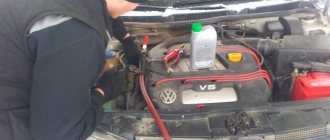
A loaded UAZ weighs almost two and a half tons, and until recently the effectiveness of its brakes was determined solely by the size of the boot and the physical training of the driver. In general, this suited the main customer of the car, the Ministry of Defense, but unpretentious Ulyanovsk jeeps also end up in the hands of civilians who want comfort. This is partly why the main brake cylinder has recently been equipped with a vacuum booster, which greatly facilitates braking. But what about those whose UAZ is deprived of such a useful device? You can fill the gap on your own.
| Unscrewing... | ...and remove the brake pedal pin. | Unscrew the two nuts securing the brake cylinder to the adapter plate. |
| Move the cylinder aside. | Holding the nuts... | ...we unscrew the four bolts securing the adapter plate to the front panel of the cab. |
| Using the contour of the part as a guide, we cut out a central hole and four more for the screws of the vacuum amplifier. | We finally adjust the “vacuum” to the plate... | ...and tighten the nuts. |
| By moving the fork along the threaded rod, we adjust the size from the center of the hole to the body within 131–133 mm. | The recess of the rod from the mating plane of the “vacuum” should be 1.35–1.65 mm. | Loosen the locknut and rotate the rod to make the necessary adjustments. |
| We install the adapter plate on the cab shield, attach the vacuum booster to it, and then the main brake cylinder. | Screw on the brake cylinder. | . and, having screwed a fitting into the intake manifold instead of a plug, we connect it with a copper tube to the vacuum chamber of the amplifier. |
Vacuum brake booster for UAZ “Bukhanka”
Many owners of a vehicle such as the UAZ Bukhanka want to improve the braking dynamics of their car. To do this, experts advise installing a vacuum brake booster instead of the standard mechanism.
This replacement will allow drivers to receive several important advantages:
- In case of sudden braking, the car does not start to pull to the side;
- To brake, you just need to touch the brake pedal;
- The brake pads do not make any extraneous sounds;
- The device is reliable and works without any failures.
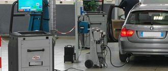
Bleeding the brakes of a UAZ Bukhanka: How to bleed the brakes consistently
The relationship between safety and the ability to stop in time is obvious; for this reason, bleeding the brakes of a UAZ loaf is a procedure that does not require delay. Do not forget that the correct execution and approach are directly related to the life of the driver and passengers operating the transport. Such concepts are not neglected, so studying the instructions before performing manipulations is a must.
Device
The operating principle of this mechanism is based on the influence of atmospheric pressure of the external environment directly on the discharged area. The device itself looks like a chamber, which is divided into two halves by a special elastic membrane.
Its first part is connected to the atmosphere, and the second is connected to the exhaust manifold of the engine, which creates a lower pressure. Due to different pressures, the membrane bends towards the rarefied air, and part of its energy is transferred to the elements of the car’s braking system.
Handbrake UAZ Bukhanka
The UAZ loaf handbrake is part of the car’s braking system. In normal condition, it ensures that the vehicle is held in place with the engine turned off. Malfunctions in the handbrake system can lead to accidents.
When repairing a handbrake, you should pay attention to the features of the entire mechanism as a whole.
Loaf handbrake cable
If this element of the parking brake mechanism becomes unusable, this becomes noticeable by problems with the handbrake lever - it stops lowering and the pads do not move apart.
To fix the problem, you will need to replace the parking brake cable.
When purchasing a cable, you should carefully examine the materials used for its winding - if the cable cover is made of plastic, then it can sometimes slip and gather approximately in the middle of the cable, which leads to a wedge of the cable in the casing.
In order to avoid such problems, the owners of the UAZ loaf advise carefully removing the plastic winding, putting everything down, lubricating the cable with oil or brake fluid, crimping the tip, welding the entire camping structure and grinding it.
How do you tighten the handbrake on a loaf?
It is necessary to tighten the handbrake if, when lowered, it dangles, and tension is not even observed, which is corrected after raising the handbrake lever higher.
To adjust the handbrake, it is recommended:
- remove the boxes between the seats, thus gaining access to the handbrake box;
- disconnect the cardan;
- disconnect the handbrake brake drum;
- Check the condition of the brake linings and cylinder and, if necessary, replace them.
You can also tighten the cable by gaining access to the brake drum - you need to find a square protrusion (screw head) in its lower part - turn it and adjust the cable. If necessary, you can adjust the length of the handbrake pull in this way.
They note that for this it is not necessary to remove the boxes in the cabin - just crawl under the car.
Adjusting the hand (parking) brake on the loaf
It is necessary to adjust the handbrake when the lever travel exceeds half of its maximum or the vehicle no longer holds on the slope.
To adjust you will need:
- hang up the rear wheel;
- turn on neutral and disengage the front axle;
- move the handbrake lever to the extreme forward position;
- tighten the adjusting screw so that the brake drum can be turned freely by hand;
- unscrew the locknut of the adjusting fork;
- unpin and remove the pin connecting the fork and the lever of the expansion device drive;
- align the holes in the fork and lever;
- insert a finger, pin it;
- tighten the locknut.
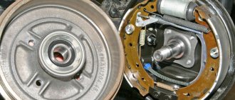
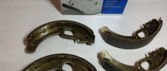
Loaf handbrake pads
The main task of this part of the brake mechanism is to hold the car in place when the parking brake is applied - they must prevent it from moving at this moment.
As a standard, parking (hand) brake pads are installed on cars that have disc rear brakes - all vehicles manufactured after 1999 have this part.
buhanka-uaz.ru
Adjustment
In some cases, after replacing the vacuum brake booster, a deterioration in the vehicle's braking is observed - for example, the system does not release the brakes completely or the brake pedal begins to press at the very end.
To fix this problem, you need to adjust the rod of the new device. This procedure is performed in the following order:
- The rod must be pushed back to the very end;
- Using a feeler gauge designed for adjusting the valve, or a regular metal ruler and caliper, the protrusion of the rod above the body is measured - it should be approximately 7.8-8.0 mm;
- If the distance does not meet the requirement, then you need to loosen the locknut, and then, using the adjusting screw, adjust the required length of the rod and fix the locknut back.
Repair of VUT and main brake cylinder of UAZ Hunter 31519
Symptoms of the problem:
The brake pedal suddenly became soft, but it doesn’t just fall right away, but when pressed for the first time it smoothly goes down all the way. At the same time, the car smoothly reduces speed. When you press it again, the pedal becomes harder, the car brakes almost normally (taking into account the fact that there are still drums behind), but the pedal slowly reaches the stop.
Inspection of the UAZ:
1. Brake fluid does not leave the reservoir. 2. A visual inspection of the brake lines and hoses did not reveal any leaks. 3. The brake master cylinder is dry. 4. Checking the condition of the front brake pads showed: pad wear is 15-20% 5. Checking the condition of the rear brake pads has not yet been carried out. 6. The patient has a “sorcerer” (from the factory).
Procedures performed:
Today the brake system was bled. All four wheels are bled. One 455 ml bottle of DOT4 brake fluid has been used. Before bleeding, the brake fluid reservoir was at the MAX level. Provided that, according to the Hunter's Primer, there is 0.6 liters of brake fluid in the hydraulic brake system, we can assume that the system is completely bled and there is no air in the system. The treatment didn't help.
It was noticed that when pumping, brake fluid came out of the air release valves of the front brakes under pressure (in a powerful stream) and in a large volume. When bleeding the rear brakes (with the same number of “pumps”), the pressure was weak, the volume of fluid flowing out was less than from the front ones). This may be normal, but it may come in handy for a correct diagnosis.
joint replacement of the vacuum booster and the main brake cylinder.
I found a lot of positive reviews, and even enthusiasm from UAZ drivers, VUT produced by Avtodetal-Service OJSC. This is not advertising! It’s decided - I’m buying VUT and GTZ from ADS. I didn’t even try to look for such a VUT in Kolomna, since the probability is “extremely small” (c) and the price tag will be “horrible”. I need to go to the capital... Early on a frosty morning I board the train to Moscow. The carriages are full of people for whom the two and a half hour trip to Nerezinovaya is just everyday work. Having bought everything I need, I return to the province. So: 42020.3151-3510010 – Vacuum brake booster JSC “ADS” – 2410 rubles.
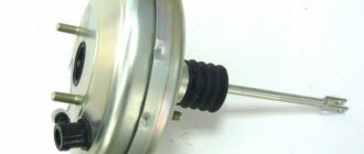
Vacuum brake booster
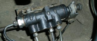
3160-3505010 – Main brake cylinder JSC “ADS” – 1240 rub.
Brake master cylinder
3160-3506060 – Front brake hose “Fenox” (there was no ADS) – 340 rub. for two pieces. It's always good to have some in stock.
General view of the purchase
On a clear Saturday afternoon, my friend and I are driving to the garage to work on the brakes.
Replacement and repair of the vacuum brake booster of VAZ and UAZ
The effectiveness of your car's brakes is important - if the brake system does not work effectively, an accident may occur. To ensure precise brakes, a booster is installed on all modern cars; it ensures that the vehicle stops instantly when you press the pedal.
Repair of the vacuum brake booster is necessary if the brakes become “wobbly” and you have to press the pedal with great force to brake.
Repair of vacuum brake booster VAZ 2106, 2107, 2108, 2109, 2110
The vacuum brake booster (abbreviated as VUT) of VAZ vehicles makes the driver’s work easier - it enhances the effect of pressing the pedal in the braking system (TS). This unit consists of the following main parts:
- valve;
- metal case;
- diaphragms;
- piston;
- rod;
- powerful return spring;
- a pusher that connects to the brake pedal;
- protective cover;
- flange for installing a check valve.
The body of the device is divided into two halves by a diaphragm, and the master brake cylinder is installed on the side where the vacuum is created. A vacuum (vacuum) is created by connecting this part of the housing to the intake manifold of the internal combustion engine, and when the engine is not running, the channel closes the check valve installed in the VUT flange. Air (vacuum) with the help of a rod and piston when pressing the brake enhances the braking effect, thereby making the driver’s work easier - there is no need to press the pedal with great force. After releasing the pedal, a powerful return spring allows the diaphragm inside the housing to return to its original position. When the engine is turned off, no vacuum is created in the system and the vacuum brake booster does not operate.
On VAZ-2106-07 and VAZ-2108-10 cars, brake boosters are installed that differ in appearance, but the principle of operation of the devices is the same. We check the serviceability of the VUT as follows: press the brake pedal and start the engine - if the pedal “falls” (lowers under the pressure of the foot), the VUT works.
Working brake system of UAZ Bukhanka
Service brake system diagram
The diagram allows you to study how the brake system of the UAZ Bukhanka works more clearly.
Fig. 1 Diagram of the working brake system of the UAZ Bukhanka: 1 – brake disc; 2 – front wheel brake bracket; 3 – outline of the front part; 4 – main brake cylinder; 5 – reservoir equipped with a brake fluid movement sensor to the emergency level; 6 – amplifier with vacuum; 7 – pusher; 8 – brake pedal; 9 – light switch when braking; 10 – rear wheel brake pads; 11 – rear wheel braking cylinder; 12 – outline of the rear part; 13 – casing of the axle axle at the rear; 14 – load spring; 15 – pressure regulator; 16 – rear cables; 17 – equalizer; 18 – central cable; 19 – parking brake lever; 20 – indicator of brake fluid movement to the emergency level; 21 – parking brake warning switch; 22 – front wheel brake pads.
Hydraulic drive of the service brake system
Since 1985, the hydraulic drive of the UAZ service brake system began to be produced with two separate branches, one of which extends to the brake mechanisms of the front wheels, and the second extends to the brake mechanisms of the rear wheels. The drive design includes:
- master brake cylinder;
- a brake pedal, which is connected to the cylinder through its piston;
- wheel cylinders of wheel brake mechanisms, both in the front and rear of the car;
- pipelines and hoses that connect all cylinders;
- control pedal and drive force amplifiers.
The lines, the inside of the master cylinder, and all wheel cylinders contain brake fluid.
When installing a brake force regulator and an anti-lock braking system modulator on a UAZ, they are also placed in the hydraulic drive structure.
The principle of operation of the UAZ brake system
When you press the pedal, the brake system operates in the following sequence:
- The master cylinder piston moves fluid into the lines and wheel cylinders;
- in the wheel cylinders, the brake fluid causes all the pistons to move, as a result of which the brake pads move closer to the drums;
- when there is no distance left between the pads and the drums, the release of fluid from the main brake cylinder will stop;
- When you press the pedal harder, the fluid pressure in the drive rises and braking of all wheels starts at the same time.
Greater force applied to the pedal results in greater pressure exerted by the master cylinder piston on the fluid, as well as greater force exerted by all the wheel cylinder pistons on the brake shoe.
This suggests that the simultaneous operation of all brakes and the regular relationship between the force on the brake pedal and the driving forces of the brakes are created thanks to the hydraulic drive system.
Removing the vacuum booster 2106-07
Removing the VUT on a VAZ classic car is quite simple, and if you have minimal plumbing skills, this work is not difficult to complete. We remove the unit as follows:
- we turn off the engine, disconnect the main brake cylinder (GTC) from the “vacuum chamber”, the cylinder is held on by two nuts. There is no need to disconnect the brake pipes and hoses from the turbocharger; we simply move the cylinder to the side;
- we pull the hose off the check valve, while holding the valve so as not to pull it out and break it;
- in the cabin, remove the fixing bracket on the brake pedal and release the VUT pusher;
- then in the cabin we unscrew the four nuts that hold the “vacuum unit”, dismantle the unit - it is removed in the engine compartment.
Disassembling vacuum booster 2109
It is not difficult to disassemble VUT 2108-2109, but for disassembly it is necessary to fix the device. We disassemble the node in the following order:
- clamp the “vacuum sealer” in a vice;
- using a screwdriver on the body, we bend the grooves with which the two halves are held together;
- when almost all the rivets are straightened, it is necessary to hold the outer part of the body - a spring is installed inside the device, and it can shoot. If the old diaphragm is put back into place, there is no need to push the screwdriver far inward, as the rubber seal may be damaged;
- remove the rubber covers from the fastenings (2 pcs.);
- dismantle the plastic casing together with the diaphragm and pusher assembly;
Typically, the repair kit for the VAZ-2109 vacuum amplifier contains a diaphragm, a cuff, a boot, covers (2 pcs.) and a valve. All parts should be changed so that you don’t have to redo the work later. When assembling a vacuum amplifier, it is better to immediately fix the diaphragm on a plastic casing, this will make it easier to mount the unit.
It doesn’t matter which side the spring is placed on, but when assembling the amplifier, you will have to make an effort to get the holes in the housing onto the studs.
Repair of UAZ vacuum brake booster
Problems with the vacuum booster of UAZ vehicles can be identified by the following symptoms:
- the engine suffers, and since on UAZ engines the vacuum hose goes to the manifold of the first cylinder, if the VUT is faulty, this particular cylinder is not completed;
- a hissing is heard under the hood - the diaphragm is poisoning the air;
- the brake pedal is hard and does not press when starting the engine;
- There are wet leaks between the turbocharger and the amplifier (brake fluid is leaking).
If leaks of the brake fluid are detected in the area of the VUT, it is necessary to urgently change or repair the GTZ, but if the liquid has already entered the vacuum booster, most likely the VUT will also have to be repaired.
Another common malfunction in the brake system is failure of the check valve. This simple mechanism is very easy to check - you just need to blow into it. The valve should be blown freely in one direction (when rarefied air is supplied from the manifold), but air flows in the opposite direction with great difficulty. If the valve is faulty, it is blown freely in both directions.
Replacing VUT on UAZ vehicles
The amplifier is removed on cars produced by the Ulyanovsk Automobile Plant according to the same principle as on VAZ cars. Let's consider replacing VUT using the example of a UAZ-31519 car:
- first of all, we unscrew the two fastenings of the GTZ to the “vacuum”, usually the cylinder is secured with nuts 17, without disconnecting the brake pipes, we move it to the side;
- under the hood, in the area of the windshield, unscrew the 2 bolts of the VUT amplifier bracket, the standard bolts are 14 mm turnkey;
- in the cabin, at the connection of the rod with the brake pedal, pull out the cotter pin; for this you will need pliers;
- remove the connecting pin;
the two lower nuts of the amplifier bracket are located in the car interior, they are turnkey 17, unscrew this fastener;
- pull off the hose from the fitting of the device, dismantle the VUT;
- disconnect the bracket from the “vacuum” - to do this, unscrew the four nuts (they are 17 mm);
- the check valve is not included with the part, so we move it from the old VUT to the new one;
- We connect the bracket to the new amplifier, carry out the assembly - we install all the parts in their places.
Installation of disc brakes on UAZ Bukhanka
Everyone knows the loaf car. The brakes are simply amazing, amazing because they don’t exist. Drums are not interesting, and do not work in modern conditions. A set from an Ulyanovsk company has arrived, I don’t even know how to pronounce it all, but in principle it doesn’t matter. We will install front disc brakes on the civil axle.
These are Gazelle calipers, Gazelle discs, that is, roughly speaking, we will make “Gazelleoise”. I was simply blown away by the company that produces these discs. And what especially struck me was how everywhere in Russia, in principle, after assembly, working with a file is a joke, so I look at the instructions and just begin to understand that this is not a joke, this is life.
Here is the car, it has already traveled with us and was a participant in some of our films. Here, in principle, everything is fine, everything is on blocking, everything is on winches. She's basically on her way. Here we see a rather creepy drum mechanism, very old, completely ineffective. No matter what anyone says, it’s really not effective. It is very inferior to disc brakes.
Now we will dismantle it, install disc brakes, and this car will stop much better. Later it will come to the rear brakes, but for now we are working on the front ones. We have already done one side in order to check whether it turns out well or badly. It will melt normally, then let’s see what we will have here in the picture.
All the wear and tear accumulates because we go off-road. One side of the block is worn out, the other is alive. What does this mean? Uneven wear, that is, this cylinder no longer works, it has leaked and jammed. Look, it's leaking. This cylinder is dry, it is rusty - a sensation.
One leaked and the other rusted, but the car stops very poorly. We remove all this. We had such a system and water here in the hub. But oddly enough, the blue lubricant that is here – it resists. Why don't we unscrew it right away? I explain - so as not to air the system ahead of time.
Let's start by installing the bracket under the disc caliper. Now all this needs to be collected. Now we will change the lubricant here and clean it. Here's a fairy tale we use. This is the adjustment plate so that when we install the disk here, it can be moved close to the caliper when installed, either too far or too close. But here it turns out that there is very little space for the caliper.
We tighten the old bolts. The most interesting thing is that if we put too much, we will have to disassemble this entire structure again and reassemble it. Tighten and insert the bolts at your place of residence. You have to press, you have to. Otherwise how. The most interesting thing is that if we miscalculated, put too much, then we will have to disassemble this structure all over again and reassemble it.
The next step of our ballet is the Gazelle support itself. Now it will be possible to put it in place, about this now in more detail. I think we’ll disassemble the caliper, remove the working cylinder so that it’s easier for us to install the whole thing, and we’ll put it all back together without difficulty.
There were a lot of plates. It’s affecting us now, which means it’s too much. This means you need to shoot how many - one or two. In reverse order, this is all taken apart, the plate is removed, and put back on. This is why the plates are made thin so that one can be removed and adjusted. Let's take the second one. In principle, everything coincides with us, nothing is touching anywhere, there is an even gap everywhere, the disk is intact. We put the pads in their place, the cool Tornado pads that were mentioned at the very beginning. They even fit into their seats.
Our system is assembled, the hoses are connected, the brakes are bled, now we install the wheel, adjust the wheel bearing - the car is ready to go. Disc brakes on the loaf. Here are the two new brake mechanisms that were installed here. The vehicle is a combat vehicle, the war paint on the bridges is immediately visible.
buhanka-uaz.ru
Features of repair of UAZ vacuum amplifiers
Unlike the vacuum amplifiers of VAZ cars, the VUT housing on UAZ cars is very durable, and it is not at all easy to halve it. You can bend the protrusions using a pry bar and a hammer, but this way the work is done in violation of the technology - according to the instructions, you need to rotate one half relative to the other. The biggest problem during disassembly is the “halving” of the body - sometimes these parts boil so much that it is impossible to disassemble the assembly. Car owners are advised not to press one body into another under any circumstances - then turning will definitely not work.
Another problem in repairing “vacuum units” is the low quality of spare parts in the repair kit; sometimes the installed parts are not enough for six months. Motorists advise not to do repairs, but to buy a new spare part, although there is another disadvantage - VUT for cars like UAZ-469 or UAZ-452 is not cheap, about 3 thousand rubles. As an option, you can pick up a “vacuum” from a foreign car at a car disassembly shop, whose mountings fit the main brake cylinder, and install it on the car by fitting it. The result is cheaper and more reliable - imported parts, even in used condition, last for several years without any complaints.
UAZ LOAF Topic author Maxim
Brake fluid quality testers
guys, help, UAZ loaf 2020, you constantly have to pump the clutch, the fluid doesn’t go away, the pedal goes to the very bottom, you don’t have time to remove your foot, the car is already moving, pumping helps a little (but not for long), air is observed in the fluid,
Roma (Jager) Look in the thread somewhere there is air
Maxim (Kristie) where exactly in the thread?
Roma (Jager) Look from the main thing to the worker, I had nothing on the brake system, nothing was leaking anywhere, but air was flowing. Well, purely by chance I found a threaded connection that was sucking air into the system
Kostya (Well) maybe it’s the cuff of the master cylinder.
Maxim (Kristie) thanks, I’ll check it
Nikolay (Aksita) Unscrew the tube from the main one and bleed it, press it with your finger so that air does not get sucked in
Andrey (Philana) The master cylinder needs to be changed. If you buy a new one, then only with a return guarantee, I have 4 pieces. I was only able to pump one normally! I fucked for two days, the batch was probably defective.
Nikolay (Aksita) It’s just that these GCs need to be pumped before installation on the car.
Ivan (Boutros) look at the clutch tabs, they unscrew themselves
Maxim (Kristie) what does the air in the system have to do with it?
Ivan (Boutros) maxim you are wrong
Maxim (Kristie) I don’t understand you
Ivan (Boutros) I didn’t write about air
Vyacheslav (Yuna) ....replacing the clutch master cylinder will help very quickly...
Vyacheslav (Yuna) and all this is pumped together with the working cylinder... this is not a shock absorber that needs to be pumped before installation on the car... something like this....
Tolik (Peder) and listen, dear friend, by chance the fork didn’t bend on the release lever, and such crap happened and everyone sinned on the main one???
Maxim (Kristie) Well, then air pumping also helps
Tolik (Peder) try the Hz change if it helps until you try everything you won’t understand, at one time there was a hemorrhage with the front sports brakes, they kept it just done, went through everything and listened to advice, but the reason was petty, the spring from the pedal fell off, so all the brakes were held at half strength, warm up the discs
Tolik (Peder) search and you will find
Nikolay (Aksita) First check for worn out lugs on the levers and wear of the pin on the master cylinder and then get into the weeds.
Quick brake bleeding after replacing the turbocharger? — uazbuka.ru
Tell me, is it possible to do without completely bleeding the system in... me from a Lada, it also fits the main brake cylinder of a Lada,... I can’t bleed the brakes on a loaf!!!
How to bleed the master brake cylinder:: how to bleed...
Those car owners who have changed the master brake cylinder in their car at least once in their life know how difficult it is...
Adjusting the rod of the vacuum brake booster UAZ
Often, after replacing the VUT, problems appear, and the car no longer brakes as well as it did before with a working “vacuum system” - the brake pedal takes off at the very end, or the system does not fully release the brakes. The whole point here is the rod that presses on the GTZ piston - it may not be adjusted from the factory. This rod has an adjusting screw, which is secured with a locknut. On UAZ cars (we don’t take the “Patriot” model into account), we check the rod adjustment as follows:
- push the rod all the way back;
- take a metal ruler or feeler gauge to adjust the valves and lay it along the body;
- We measure the protrusion above the body with a caliper - the rod should extend approximately 7.8-8.0 mm;
- if this distance does not correspond to the norm, loosen the lock nut and use the adjusting screw to increase or decrease the length of the rod;
- Having established the desired size, fix the screw with a lock nut.
Even on the UAZ Hunter, the pedal can “take” at the very end, and it has a large free play. It is necessary to pay attention to the position of the pedal - if it is too low from the floor in the cabin, it needs to be adjusted:
- unscrew the brake light mounting nuts on the brake pedal;
- disconnect the wires from the brake light sensor;
- Use two 19 mm nuts to raise the pedal, press the brake to check the free play, and if the pedal is adjusted normally, tighten the nuts.
source
content .. 51 52 ..UAZ-3151. Service brake system
Shoe brakes are installed on all vehicle wheels. The front brake mechanisms are structurally different from the rear ones. The front brake mechanisms of cars with axles with final drives are distinguished by shields that have a different stamping, a set of brake cylinders and connecting pipes of the cylinders, as well as the working position of the cylinders. The rear brake mechanisms of these cars differ only in their shields.
| Rice. 6.1. Front wheel brake mechanism: a – marks on the support pins; 1 – shield; 2 – connecting tube; 3 – wheel brake cylinder; 4 – bypass valve; 5 – coupling; 6 – tension spring of pads; 7 – pad lining; 8 – brake pad; 9 – protective cap; 10 – piston; 11 – sealing rings; 12 – piston spring; 13 – adjusting eccentric; 14 – support pin of the block; 15 – nut; 16 – coupling bolt; 17 – gaskets; 18 – support sleeve; 19 – bolt of the adjusting eccentric; 20 – washer |
| Rice. 6.2. Rear wheel brake mechanism: a – marks on the support pins; 1 – support finger; 2 – shield; 3 – eccentric; 4 – eccentric axis head; 5 – wheel brake cylinder; 6 – bypass valve; 7, 13 – brake pads; 8 – protective cap; 9 – piston; 10 – sealing rings; 11 – piston spring; 12 – tension spring |
The basic design of the brake mechanisms of the front and rear wheels is shown in Fig. 6.1 and 6.2.
| Rice. 6.3. Drive of the service brake system of vehicles of the UAZ-31512 family: 1 – signaling device; 2 – switch for the warning lamp of the emergency condition of the hydraulic brake system; 3 – tanks; 4 – body of the main brake cylinder; 5, 8 – nuts; 6 – vacuum booster; 7 – plate; 9 – pedal axis; 10 – fork; 11 – finger; 12 – pedal; 13 – emphasis; 14 – brake signal switch; 15 – tension spring; 16 – bracket |
| Rice. 6.5. Vacuum booster: 1 – cover of the secondary chamber; 2 – piston of the secondary chamber; 3 – check valve; 4 – spring; 5 – nut; 6 – stop; 7 – rod; 8 – washer; 9 – rod seal; 10,12,37 – lock washers; 11 – sealing ring; 13 – sealing cuff of the cover; 14 – diaphragm plate; 15 – cover guide ring; 16 – cover of the primary chamber; 17 – support ring; 18 – diaphragm of the secondary chamber piston; 19 – connector; 20 – buffer; 21 – control valve diaphragm spring; 22 – diaphragm of the primary chamber piston; 23 – amplifier housing; 24 – piston of the primary chamber; 25 – valve body; 26 – thrust washer; 27 – housing guide ring; 28 – body sealing collar; 29 – valve piston; 30 – air filter; 31 – protective cover; 32 – pusher fork; 33 – pusher; 34 – spring bushing; 35 – valve spring; 36 – control valve seal; 38 – cotter pin; wire; 39 – valve diaphragm; 40 – stop screw; I, II – atmospheric cavities; III, IV – vacuum cavities |
| Rice. 6.6. Master brake cylinder: 1 – cover; 2 – gasket; 3 – mesh; 4 – tank; 5 – fitting; 6, 8, 15 – gaskets; 7 – plug; 9 – plug insert; 10 – spring; 11 – spring seat; 12 – washer; 13.19 – pistons; 14 – thrust bolt; 16 – spring holder; 17 – stop screw; 18 – sealing collar; 20 – sealing ring; 21 – thrust washer; 22 – retaining ring |
| Rice. 6.7. Signaling device: 1 – housing; 2 – fitting; 3 – switch; 4, 8 – gaskets; 5 – plug; 6 – long piston; 7 – short piston |
The service brake system drive (Fig. 6.3 and 6.4) includes a pedal, a vacuum booster (Fig. 6.5), a two-chamber master cylinder (Fig. 6.6), a signaling device (Fig. 6.7), pipelines with connecting fittings and wheel cylinders.
| Rice. 6.8. Pressure regulator: 1 – piston; 2 – piston sealing ring; 3, 6 – piston spring support washers; 4 – piston spring; 5 – body; 7 – piston head seal; 8 – body bushing; 9 – pusher bushing support washer; 10 – pusher bushing; 11 – sealing ring of the pusher; 12 – support plate; 13 – pusher bushing spring; 14 – plug; 15 – plug gasket; 16 – bypass valve; 17 – plug; 18 – piston sleeve; 19 – retaining ring; 20 – protective cover |
On some vehicles, a pressure regulator can be installed in the hydraulic drive system (Fig. 6.8), which automatically adjusts the brake fluid pressure in the rear wheel brakes depending on the load on the vehicle.
Maintenance
Constantly monitor the serviceability of the service brake system, adjust it in a timely manner and eliminate any malfunctions that arise.
Systematically check the fluid level in the master cylinder reservoirs and, if necessary, bring it up to normal. The level should be 15–20 mm below the upper edges of the filling holes. Make sure the connections of the hydraulic drive pipelines are tight. Check the condition of the pipelines and the reliability of the pipes on the frame and rear axle. During inspections, make sure that there is no damage to tubes and flexible hoses. Replace damaged pipes and hoses with new ones.
| Rice. 6.9. Pressure regulator drive: a – vehicles of the UAZ-31512 family; b – vehicles of the UAZ-3741, UAZ-3962, UAZ-2206, UAZ-3303 family and their modifications on UAZ-33036, UAZ-39094, UAZ-39095 vehicles, the regulator is installed on the opposite side of the frame cross member; 1 – pressure regulator; 2 – bracket (base); 3 – drive lever; 4 – adjusting bolt; 5 – elastic lever; 6, 9, and 13 – bolts; 7 – bushing; 8 – lever stand; 10 – spacer sleeve; 11 – terminal; 12 – rack bracket; 14 – lever axis |
During seasonal maintenance, check the operation of the pressure regulator. Clean the regulator from dirt and check the reliability of its fastening. By external inspection, make sure that the regulator and its drive parts are not damaged, there are no leaks of brake fluid and there are no gaps in the connection of the strut with the elastic lever and the bracket on the rear axle (Fig. 6.9).
When you press the brake pedal, piston 1 (see Fig. 6.8) of the pressure regulator should move out of the housing by 1.7–2.3 mm. Lack of piston stroke, as well as insufficient or excessive stroke, indicates a malfunction of the regulator or its drive.
When inspecting the hydraulic drive, pay attention to the location of the plastic (control) plug 17 and the absence of brake fluid leaking from under it. In normal condition, the plug should be recessed into the hole in the regulator body until it stops. The protrusion of the plug from the hole and the leakage of brake fluid mean a loss of tightness of the sealing rings 11 and, as a consequence, the functionality of the regulator.
As necessary, check the reliability of the vacuum booster, wash or replace the booster air filter.
Periodically remove the brake drums and clean the brake parts from dirt. In summer and when driving on dirty roads, clean more often.
When removing the brake drum, make sure that there are no leaks from the wheel brake cylinders, as well as that the wheel cylinders are securely attached to the shields. Pay attention to the condition of the wheel cylinder protective caps, the degree of wear of the friction linings, and the condition of the brake drum. If the surfaces of the linings become oily, clean them with sandpaper.
With the hubs removed, tighten the brake shield bolts.
Regularly flush the hydraulic drive and fill it with fresh brake fluid. To thoroughly flush the hydraulic drive, disassemble the main and wheel brake cylinders, the pressure regulator, and blow out the pipelines with compressed air.
When disassembling cylinders, maintain cleanliness. Wash rubber and metal parts of the cylinders in clean brake fluid. Do not use kerosene or gasoline, as this will cause swelling of the rubber parts and failure of the brake system. During assembly, it is recommended to lubricate the working parts of the cylinders with brake fluid.
content .. 51 52 ..