The Truth About Train Brakes: Part 2
I see that the public liked the first, historical part of my story, and therefore it’s not a sin to continue. High-speed trains like the TGV no longer rely on air braking
Today we will talk about modernity, namely, what approaches to creating brake systems for rolling stock are used in the 21st century, which is literally entering its third decade in just a month.
Based on the physical principle of creating braking force, all railway brakes can be divided into two main types:
frictional
, using friction force, and
dynamic
, using a traction drive to create a braking torque.
Friction brakes include shoe brakes of all designs, including disc brakes, as well as magnetic rail brakes
, which is used in high-speed long-haul transport, mainly in Western Europe. On track 1520, this type of brake was used exclusively on the ER200 electric train. As for the same Sapsan, Russian Railways refused to use a magnetic rail brake on it, although the prototype of this electric train, the German ICE3, is equipped with such a brake.
ICE3 train bogie with magnetic rail brake
Sapsan train trolley
To dynamic, or rather electrodynamic brakes
include all brakes, the action of which is based on the transfer of traction electric motors to generator mode (
regenerative
and
rheostatic brake
), as well as
counter-
With regenerative and rheostatic brakes, everything is relatively clear - the engines are transferred to generator mode in one way or another, and in the case of recuperation release energy into the contact network, and in the case of a rheostat, the generated energy is burned on special resistors. Both brakes are used both on trains with locomotive traction and on multiple unit rolling stock, where the electrodynamic brake is the main service brake, due to the large number of traction motors distributed throughout the train. The only disadvantage of electrodynamic braking (EDB) is the impossibility of braking to a complete stop. When the efficiency of the EDT decreases, it is automatically replaced by a pneumatic friction brake.
As for counter-braking, it provides braking to a complete stop, since it consists in reversing the traction motor while moving. However, this mode, in most cases, is an emergency mode - its normal use is fraught with damage to the traction drive. If we take, for example, a commutator motor, then when the polarity of the voltage supplied to it changes, the back-EMF that arises in the rotating motor is not subtracted from the supply voltage but added to it - the wheels both rotated and rotate in the same direction as in traction mode! This leads to an avalanche-like increase in current, and the best that can happen is that the electrical protection devices will operate.
For this reason, on locomotives and electric trains, all measures are taken to prevent engines from reversing while moving. The reversing handle is locked mechanically when the driver's controller is in the running positions. And on the same Sapsan and Lastochka vehicles, turning the reverse switch at a speed above 5 km/h will lead to immediate emergency braking.
However, some domestic locomotives, for example the VL65 electric locomotive, use reverse braking as a standard mode at low speeds.
Reverse braking is a standard braking mode provided by the control system on the VL65 electric locomotive
It must be said that despite the high efficiency of electrodynamic braking, any train, I emphasize, is always equipped with an automatic pneumatic brake, that is, activated by releasing air from the brake line. Both in Russia and throughout the world, good old friction shoe brakes stand guard over traffic safety.
According to their functional purpose, friction type brakes are divided into
- Parking, manual or automatic
- Train - pneumatic (PT) or electro-pneumatic (EPT) brakes, installed on each unit of rolling stock on the train and controlled centrally from the driver’s cab
- Locomotive - pneumatic direct-acting brakes designed to slow down a locomotive without slowing down the train. They are managed separately from trains.
The manual brake with a mechanical drive has not disappeared from the rolling stock; it is installed on both locomotives and cars - it just changed its specialty, namely, it turned into a parking brake, which makes it possible to prevent spontaneous movement of the rolling stock in the event of air escaping from its pneumatic system.
The red wheel, similar to a ship's wheel, is a handbrake drive, one of its variants. Handbrake steering wheel in the cabin of the VL60pk electric locomotive
Handbrake in the vestibule of a passenger car
Handbrake on a modern freight car
The handbrake, using a mechanical drive, presses the same pads against the wheels that are used during normal braking.
On modern rolling stock, in particular on the electric trains EVS1/EVS2 “Sapsan”, ES1 “Lastochka”, as well as on the electric locomotive EP20, the parking brake is automatic and the pads are pressed against the brake disc using spring energy accumulators
. Some of the pincer mechanisms that press the pads to the brake discs are equipped with powerful springs, so powerful that the release is carried out by a pneumatic drive with a pressure of 0.5 MPa. The pneumatic drive, in this case, counteracts the springs that press the pads. This parking brake is controlled by buttons on the driver’s console.
Buttons for controlling the parking spring brake (SPT) on the electric train ES1 “Lastochka”
The design of this brake is similar to that used on powerful trucks. is completely unsuitable as the main brake on trains.
, and why, I will explain in detail after the story about the operation of train air brakes.
Each freight car is equipped with the following set of brake equipment
Freight car brake equipment: 1 - brake connecting hose; 2 - end valve; 3 - stop valve; 5 - dust collector; 6, 7, 9 — air distributor modules condition. No. 483; 8 - disconnect valve; VR - air distributor; TM - brake line; ZR - reserve tank; TC - brake cylinder; AR - cargo auto mode
Brake line
(TM) - a pipe with a diameter of 1.25" running along the entire car, at the ends it is equipped with
end valves
to disconnect the brake line when uncoupling the car before disconnecting the flexible connecting hoses.
In the brake line, in normal mode, the so-called charging
pressure of 0.50 - 0.54 MPa is maintained, so disconnecting the hoses without shutting off the end valves is a dubious task, which can literally deprive you of your head.
The supply of air directly supplied to the brake cylinders is stored in a reserve tank
(ZR), the volume of which in most cases is 78 liters. The pressure in the reserve reservoir is exactly equal to the pressure in the brake line. But no, it’s not 0.50 - 0.54 MPa. The fact is that such pressure will be in the brake line on the locomotive. And the further away from the locomotive, the lower the pressure in the brake line, because it inevitably has leaks leading to air leaks. So the pressure in the brake line of the last car on the train will be slightly less than the charging one.
Brake cylinder
, and on most cars there is only one; when it is filled from a spare tank, through a brake lever transmission it presses all the pads on the car to the wheels. The volume of the brake cylinder is about 8 liters, so during full braking, a pressure of no more than 0.4 MPa is established in it. The pressure in the reserve tank also decreases to the same value.
The main “actor” in this system is the air distributor
. This device reacts to changes in pressure in the brake line, performing one or another operation depending on the direction and rate of change of this pressure.
When the pressure in the brake line decreases, braking occurs. But not with any decrease in pressure - the decrease in pressure must occur at a certain pace, called the service braking rate
.
This rate is provided by the driver's crane
in the locomotive cabin and ranges from 0.01 to 0.04 MPa per second. When the pressure decreases at a slower rate, braking does not occur. This is done so that the brakes do not operate in the event of standard leaks from the brake line, and also do not operate when overcharging pressure is eliminated, which we will talk about later.
When the air distributor is activated for braking, it performs an additional discharge of the brake line at a service rate of 0.05 MPa. This is done in order to ensure a steady decrease in pressure along the entire length of the train. If additional detente is not done, then the last cars of a long train may not be slowed down at all. Additional discharge of the brake line is carried out by all
modern air distributors, including passenger ones.
When braking is activated, the air distributor disconnects the reserve reservoir from the brake line and connects it to the brake cylinder. The brake cylinder is filling. It occurs exactly as long as the pressure drop in the brake line continues. When the pressure reduction in the brake fluid stops, filling the brake cylinder stops. shutdown mode is coming
. The pressure built into the brake cylinder depends on two factors:
- the depth of discharge of the brake line, that is, the magnitude of the pressure drop in it relative to the charging
- air distributor operating mode
The cargo air distributor has three operating modes: loaded (L), medium (C) and empty (E).
These modes differ in the maximum pressure gained into the brake cylinders. Switching between modes is done manually by turning a special mode handle. To summarize, the dependence of the pressure in the brake cylinder on the depth of discharge of the brake line with a 483-air distributor in various modes looks like this
The disadvantage of using a mode switch is that the car operator must walk along the entire train, climb under each car and switch the mode switch to the desired position.
According to rumors coming from the operation, this is not always done. Excessive filling of the brake cylinders on an empty car is fraught with skidding, reduced braking efficiency and damage to wheel sets. To get out of this situation, on freight cars, between the air distributor and the brake cylinder, the so-called auto mode
(AR) is turned on, which, mechanically determining the mass of the car, smoothly regulates the maximum pressure in the brake cylinder. If the car is equipped with an auto mode, then the mode switch on the VR is set to the “loaded” position.
Braking is usually performed in stages. The minimum level of brake line discharge for BP483 will be 0.06 - 0.08 MPa. In this case, a pressure of 0.1 MPa is established in the brake cylinders. In this case, the driver places the valve in the overlap position, in which the pressure set after braking is maintained in the brake line. If the braking efficiency from one stage is insufficient, the next stage is performed. In this case, the air distributor does not care at what rate the discharge occurs - when the pressure decreases at any rate, the brake cylinders are filled in proportion to the amount of pressure decrease.
Complete brake release (complete emptying of the brake cylinders on the entire train) is performed by increasing the pressure in the brake line above the charging pressure. Moreover, on freight trains, the pressure in the TM is significantly increased above the charging one, so that the wave of increased pressure reaches the very last cars. Completely releasing the brakes on a freight train is a lengthy process and can take up to a minute.
BP483 has two holiday modes: flat and mountain. In flat mode, when the pressure in the brake line increases, a complete, stepless release occurs. In mountain mode, it is possible to release the brakes in stages, which means that the brake cylinders are not completely emptied. This mode is used when driving along a complex profile with large slopes.
The air distributor 483 is generally a very interesting device.
A detailed analysis of its structure and operation is a topic for a separate large article. Here we looked at the general principles of operation of the cargo brake. Braking equipment of a passenger car: 1 - connecting hose; 2 - end valve; 3, 5 — connecting boxes for the electro-pneumatic brake line; 4 - stop valve; 6 — tube with electro-pneumatic brake wiring; 7 — insulated suspension of the connecting sleeve; 8 - dust collector; 9 — outlet to the air distributor; 10 - disconnect valve; 11 — working chamber of the electric air distributor; TM - brake line; VR - air distributor; EVR - electric air distributor; TC - brake cylinder; ZR - spare tank
A large amount of equipment immediately catches your eye, starting with the fact that there are as many as three stop valves (one in each vestibule, and one in the conductor’s compartment), ending with the fact that domestic passenger cars are equipped with both pneumatic and electro-pneumatic brakes
(EPT).
An attentive reader will immediately note the main drawback of pneumatic brake control - the final speed of propagation of the braking wave, limited above by the speed of sound. In practice, this speed is lower and amounts to 280 m/s during service braking, and 300 m/s during emergency braking. In addition, this speed strongly depends on the air temperature and in winter, for example, it is lower. Therefore, the eternal companion of pneumatic brakes is the unevenness of their operation in composition.
Uneven operation leads to two things - the occurrence of significant longitudinal reactions in the train, as well as an increase in braking distance. The first is not so typical for passenger trains, although containers with tea and other drinks bouncing on the table in the compartment will not please anyone. Increasing the braking distance is a serious problem, especially in passenger traffic.
In addition, the domestic passenger air distributor is like the old standard. No. 292, and the new condition. No. 242 (of which, by the way, there are more and more of them in the fleet of passenger cars), both of these devices are direct descendants of that same Westinghouse triple valve, and they operate on the difference between two pressures - in the brake line and the reserve reservoir. They are distinguished from a triple valve by the presence of an overlap mode, that is, the possibility of stepped braking; the presence of additional discharge of the brake line during braking; the presence of an emergency braking accelerator in the design. These air distributors do not provide stepwise release - they immediately provide complete release as soon as the pressure in the brake line exceeds the pressure in the reserve reservoir established there after braking. And the stepped release is very useful when adjusting braking for an accurate stop at the landing platform.
Both problems - uneven operation of the brakes and the lack of stepwise release - on the 1520 mm track are solved by installing an electrically controlled air distributor on the cars - an electric air distributor
(EVR), arb. No. 305.
Domestic EPT - electro-pneumatic brake - direct-acting, non-automatic. On passenger trains with locomotive traction, the EPT operates on a two-wire circuit.
Block diagram of a two-wire EPT: 1 - control controller on the driver’s crane; 2 - battery; 3 - static power converter; 4 — panel of control lamps; 5 — control unit; 6 — terminal block; 7 — connecting heads on the sleeves; 8 — isolated suspension; 9 - semiconductor valve; 10 - release electromagnetic valve; 11 - brake solenoid valve.
There are two wires stretched along the entire train: No. 1 and No. 2 in the figure. On the tail car, these wires are electrically connected to each other and an alternating current with a frequency of 625 Hz is passed through the resulting loop. This is done to monitor the integrity of the EPT control line. If the wire breaks, the alternating current circuit is broken, the driver receives a signal in the form of the “O” (vacation) warning lamp going out in the cab.
The control is carried out by direct current of different polarity. In this case, the wire with zero potential is the rails. When a positive (relative to the rails) voltage is applied to the EPT wire, both electromagnetic valves installed in the electric air distributor are activated: the release valve (OV) and the brake valve (TV). The first of them isolates the working chamber (WC) of the electric air distributor from the atmosphere, the second fills it from a reserve tank. Next, the pressure switch installed in the EVR comes into play, operating on the pressure difference in the working chamber and the brake cylinder. When the pressure in the RC exceeds the pressure in the TC, the latter is filled with air from the reserve tank, up to the pressure that was accumulated in the working chamber.
When a negative potential is applied to the wire, the brake valve turns off, since the current to it is cut off by the diode. Only the release valve, which maintains pressure in the working chamber, remains active. This is how the position of the ceiling is realized.
When the voltage is removed, the release valve loses power and opens the working chamber to the atmosphere. When the pressure in the working chamber decreases, the pressure switch releases air from the brake cylinders. If, after a short vacation, the driver’s valve is put back in the shut-off position, the pressure drop in the working chamber will stop, and the release of air from the brake cylinder will also stop. In this way, the possibility of stepwise brake release is achieved.
What happens if the wire breaks? That's right - EPT will release. Therefore, this brake (on domestic rolling stock) is non-automatic. If the EPT fails, the driver has the opportunity to switch to pneumatic brake control.
EPT is characterized by simultaneous filling of brake cylinders and their emptying throughout the train. The rate of filling and emptying is quite high - 0.1 MPa per second. The EPT is an inexhaustible brake, since during its operation the conventional air distributor is in the release mode and feeds the spare reservoirs from the brake line, which in turn is fed by the driver's tap on the locomotive from the main reservoirs. Therefore, the EPT can be braked at any frequency required for operational control of the brakes. The possibility of step release allows you to control the speed of the train very accurately and smoothly.
The pneumatic control of the brakes of a passenger train is not much different from the freight brake. There is a difference in control methods, for example, the air brake is released to the charging pressure, without overestimating it. In general, excessive overestimation of pressure in the brake line of a passenger train is fraught with troubles, therefore, when the EPT is completely released, the pressure in the brake line is increased by a maximum of 0.02 MPa above the value of the set charging pressure.
The minimum depth of discharge of heavy metal when braking on the passenger brake is 0.03 - 0.05 MPa, while a pressure of 0.1 - 0.15 MPa is created in the brake cylinders. The maximum pressure in the brake cylinder of a passenger car is limited by the volume of the reserve tank and usually does not exceed 0.4 MPa.
Now I will turn to some commentators who are surprised (and in my opinion, even outraged, but I cannot say) by the complexity of the train brake. The comments suggest using a car circuit with energy storage batteries. Of course, from a sofa or a computer chair in the office, through a browser window, many problems are more visible and their solutions are more obvious, but let me note that most technical decisions made in the real world have a clear justification.
As already mentioned, the main problem of a pneumatic brake on a train is the final speed of movement of the pressure drop along a long (up to 1.5 km in a train of 100 cars) brake line pipe - the brake wave. To accelerate this braking wave, additional discharge is required by the air distributor. There will be no air distributor, and there will be no additional discharge. That is, brakes on energy accumulators will obviously be noticeably worse in terms of uniformity of operation, taking us back to the times of Westinghouse. A freight train is not a truck; there are different scales, and therefore different principles for controlling the brakes. I am sure that this is not just like that, and it is not by chance that the direction of world braking science has followed the path that led us to this kind of construction. Dot.
This article is a kind of review of the braking systems existing on modern rolling stock. Further, in other articles in this series, I will dwell on each of them in more detail. We will learn what devices are used to control the brakes and how the air distributors are designed. Let's take a closer look at the issues of regenerative and rheostatic braking. And of course, let’s consider the brakes of high-speed vehicles. See you again and thank you for your attention!
PS: Friends! I would like to say special thanks for the mass of personal messages indicating errors and typos in the article. Yes, I am a sinner who is not friendly with the Russian language and gets confused on the keys. I tried to correct your comments.
Types of brake mechanisms used in cars
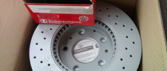
The vast majority of cars are equipped with friction-type brake mechanisms that operate on the principle of friction forces. They are installed directly in the wheel and are structurally divided into:
- drums;
- disk.
There was a tradition of installing drum mechanisms on the rear wheels and disc mechanisms on the front. Today, depending on the model, the same types can be installed on all four wheels - either drums or discs.
Design and operation of the drum brake mechanism
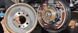
The drum-type system device (drum mechanism) consists of two shoes, a brake cylinder and a tension spring located on a shield inside the brake drum. Friction linings are riveted or glued onto the pads.
The brake pads with their lower ends are hinged on the supports, and with their upper ends - under the influence of a tension spring - they rest against the pistons of the wheel cylinder. In the unbraked position, there is a gap between the shoes and the drum, allowing the wheel to rotate freely.
When fluid enters the cylinder through the brake pipe, the pistons diverge and push the pads apart. They come into close contact with the brake drum rotating on the hub, and the friction force causes the wheel to brake.
It should be noted that in the above design, the wear of the front and rear pads occurs unevenly. The fact is that the friction linings of the front pads in the direction of movement at the moment of braking when moving forward are always pressed against the drum with greater force than the rear ones. As a solution, it is recommended to change the pads after a certain period of time.
Disc type brake mechanism
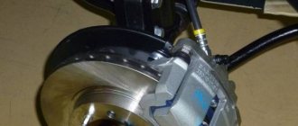
The disc brake device consists of:
- a caliper mounted on a suspension, the body of which houses the outer and inner brake cylinders (there may be one) and two brake pads;
- disk, which is attached to the wheel hub.
When braking, the pistons of the working cylinders hydraulically press the brake pads against the rotating disc, stopping the latter.
Replacing a faulty brake cylinder
The replacement scheme in the VAZ family is almost the same for cylinders of both circuits with minor differences.
Initially, you need to prepare the necessary keys and plugs suitable for the size of the pipes. After removing the wheel and unscrewing the pipes, we put plugs on them to prevent fluid leakage. Having unscrewed the corresponding nuts, we dismantle the old cylinder and put a new one in its place, reassembling it in the reverse order. If, after replacement, wheel assembly is hindered by pads that are too far apart, you can file the ends of the pads, just don’t overdo it, as this may affect the operation of the handbrake.
After any manipulations with the brake system, it must be bled according to the diagram.
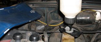
To bleed, prepare: liquid, a wrench of suitable diameter for the air fitting, a hose that fits tightly onto the fitting and any container. The pumping scheme depends on how the circuits are located in a particular VAZ model. Some brakes require bleeding from a “long line,” meaning from the furthest wheel relative to the master cylinder.
More specifically, it looks like this: in the car the master cylinder is placed looking at the rear bumper, which means that the rear right cylinder is pumped first, then the rear left one. The front left one comes next, and the procedure ends by bleeding the wheel that is located on the right side of the master cylinder. In later models, the scheme involves bleeding crosswise while looking at the car from behind:
- right rear wheel;
- left front wheel;
- left rear wheel;
- right front wheel.
In any case, bleeding should be completed with the front right wheel.
During this process, do not forget to monitor the level of hydraulic fluid in the reservoir so that air does not enter the system again.
Car brake system care
As one of the most important components, the car's braking system requires constant attention and care. Here, literally any malfunction can lead to unpredictable consequences on the road.
Some diagnoses can be made based on the behavior of the brake pedal. Thus, an increased stroke or a “soft” pedal most likely indicates that air has entered the hydraulic drive system as a result of a brake fluid leak. Therefore, it is necessary to periodically monitor the liquid level in the tank.
Its increased consumption may be a consequence of damage to hydraulic hoses and tubes, as well as ordinary evaporation over time. This causes air to enter the system and cause brake failure.
Parts that have become unusable must be replaced, and the system will have to be pumped by bleeding air from each working cylinder on the wheels and adding fluid. The process is long and tedious. When the car pulls to the side when braking, it indicates a possible failure of one of the working cylinders or excessive wear of the linings on a particular wheel. If the brake mechanisms are dirty, a characteristic noise may occur when you press the pedal.
All these malfunctions can be easily fixed independently or by contacting a service center. And to minimize the troubles described above, take care of your brakes and use engine braking more often, especially on steep and long descents. Prolonged activation of the main working system leads to overheating of parts and causes various breakdowns.
Dear friends, if you are on the pages of our blog, then it is extremely important for you to know about the brakes! I can hardly imagine how you can drive a car without brakes. Such an act can be compared, perhaps, with a kamikaze who wanted to die for the sake of the great emperor. We don’t need this, but knowing how the hydraulic braking system of a car works is very useful.
And having learned, it will be pleasant to press the brake pedal, imagining how everything moves and flows, slips and shuffles, squeaking... After all, we do not agree with the statement - “brakes were invented by cowards”
Let's get started. For optimal control of any vehicle, you need a braking system appropriate for the vehicle class. What is it for? It’s very clear here - to reduce speed, to slow down, stop and perform any maneuver.
But in case of prolonged parking, especially on a slope, a parking brake is needed to prevent spontaneous movement.
There are other braking systems. Let's get acquainted with them, their classification, types, operating principles and design features.
Modern cars are equipped with the following types of braking systems:
● working system; ● parking; ● auxiliary system; ● spare.
Service brake system
The service brake system is the main one and, accordingly, the most effective. Serves to reduce speed and stop. Activated when the driver presses the pedal
brakes, the following is a mechanism for compressing (disc-type brakes) or releasing (drum-type brakes) the brake pads of the brake mechanisms of all wheels simultaneously.
Parking brake
The parking brake system is used to ensure that the vehicle remains stationary during long-term parking. Many drivers fix the car by engaging first or reverse gear. True, on a steep slope this measure may not be enough.
The parking brake is also used for starting off on a section of road with a slope. In this case, the right foot is on the gas pedal and the left foot is on the clutch pedal. Smoothly releasing the handbrake, engage the clutch and at the same time add gas, this prevents rolling downhill.
Spare brake system
A spare brake system was developed to protect the main working one in case of failure. It can be implemented as a stand-alone device, but most often it is implemented as one of the circuits of the main system.
Assistance system
An auxiliary braking system is mainly equipped with heavy-duty vehicles such as KamAZ, MAZ, and, of course, all foreign-made trucks. Auxiliary systems reduce the load from the main one during prolonged braking, for example, in mountainous and hilly areas.
For example, the so-called mountain brake. Braking occurs by the engine when the car is moving in gear. Its principle is that for a short time, special flaps close the inlet and outlet pipes, and the fuel for engine operation is also stopped. A vacuum is created in the cylinders and the engine begins to impede the movement of the car, thereby slowing it down.
Working principle of the parking brake
It is a purely mechanical device. It is activated by raising the handbrake lever to a vertical position until the latch clicks. In this case, tension occurs on two metal cables running under the bottom of the car, which tightly press the brake pads of the rear wheels to the drums.
To release the car from the parking brake, press the locking button with your finger and lower the lever down to its original position.
Don't forget to check the position of the handbrake before you start driving! Driving with the handbrake not released will quickly damage the brake pads.
Operating principle and design of brakes
//www.youtube.com/watch?v=Av-jj8NNrv8
Let's look at the principle of operation of hydraulic brakes:
- The driver presses the pedal, which sets the piston in the master cylinder in motion. The brake booster is automatically activated, reducing the load on the brake pedal;
- The fluid transmits pressure through pipelines to the brake mechanisms, which create resistance to wheel rotation - braking occurs;
- When you remove your foot from the pedal, the return spring pulls the piston back, as a result of which the pressure decreases, the released fluid is sent back to the master cylinder - the wheels are released.
Hydraulic brake system
Brake mechanisms and hydraulic system drives:
- high pressure brake hoses;
- brake pedal;
- working brake cylinders of front and rear wheels;
- vacuum brake booster;
- pipelines;
- master brake cylinder with reservoir.
Note: Domestic rear-wheel drive cars have a circuit with separate fluid supply from the master cylinder to the front and rear wheels. Some foreign cars and front-wheel drive VAZs have a circuit diagram of “left front and right rear”, plus “right front and left rear”.
- circuit, right rear - left front brake mechanisms;
- alarm sensor
- circuit left rear - right front brake mechanisms;
- master cylinder brake fluid reservoir;
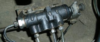
- master brake cylinder
- vacuum brake booster
- brake pedal
- pressure regulator between circuits
- brake cable, parking
- brake mechanism - rear wheel
- parking brake adjuster
- parking brake lever
- front wheel brake mechanism
Mechanical brake system
Mechanical - in the parking brake system. Although the latest models also use an electric drive, then it is called an electromechanical handbrake.
For smooth and safe operation of the brakes, modern cars are equipped with all kinds of electronic units that improve their performance: ABS, emergency brake booster, brake force distribution unit.
Pneumatic brake system
The pneumatic drive is mainly used on heavy-duty vehicles.
The difference between this system and the hydraulic system is that instead of brake fluid, air works in the system. Air pressure opens the brake pads, and the air pressure in the system is provided by a special compressor operating from the engine through a belt drive.
Combined drive
A combined drive is a combination of several types of braking systems. For example, combining a hydraulic drive with an air drive, electric and pneumatic, there are others.
