You still need to align the shafts if there are no marks. Drivers use the same tool and additionally take a flat, hard metal rod half a meter long.
Author of the article: Roman Krasinets 04/28/2020 0 0
The subtleties of what timing marks are are unfamiliar to most Passat B3 owners. Meanwhile, having sorted out the issue, you can save a lot on belt repairs.
A little theory: what is a timing belt?
It is not pure fuel that burns in the cylinders of the internal combustion engine, but the finest fuel mist mixed with air. The spark plugs ignite a homogeneous air-fuel mixture. At the moment of its ignition, the volume and temperature increase sharply - the mixture in the chamber turns into gases. Under strong pressure, the piston tends downward, makes a working stroke, and at the moment of release, it goes up and pushes the spent combustion products through the open exhaust valves, first into the manifold, then through the tubes into the atmosphere.
A cycle occurred: injection of a combustible mixture into the chambers, its ignition and release of exhaust gases. The motor cannot “know” when to open/close the corresponding valves. The gas distribution mechanism is responsible for this. The abbreviation of the unit is familiar to drivers - timing.
It is installed and connects the engine crankshaft (CV) and the camshafts (CV), which control the valves. The timing system clearly synchronizes the operation of the shafts - injects the air-fuel mixture and releases exhaust gases.
The connection (synchronization) of the shafts is carried out in the Passat B3 by the timing belt. In the power units of other cars there is a chain. Another type of connection is gears.
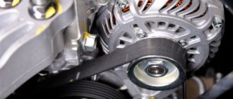
Structurally, in a Volkswagen B3 body it looks like this: a small gear is put on the crankshaft. The same gears, but 2 times larger in diameter, are also on the camshafts (due to this, the CV rotates 2 times faster than the CV). By means of a belt, the shafts are synchronized in operation. The speed of the distribution mechanisms that open/close the valves is determined by the speed of the crankshaft. The rotation speed of the car’s attachments also depends on the “knee”: pumps, air conditioning compressor.
The Passat B3 timing belt is shown in the photo.
Timing belt on Passat B3
vw audi skoda seat
Replacing timing belt on 1.9 TDI BKC
The mileage of my car has approached 120 tkm, which the car has covered on various roads over the past 5 years.
It's time to replace the timing belt, its rollers and pump according to the service plan in the service book. This photo report shows how you can perform this work on the BKC engine installed in the Audi A3. The BKC engine is also used in many other models, such as the VW Golf and VW Touran. However, the design of the engine mount may differ in them. Direct replacement of all parts - dismantling old ones and installing new ones - does not cause much labor or difficulty, although it does require concentration, accuracy, and some skills and knowledge. The main difficulties may arise when draining coolant (coolant) and filling it into the cooling system, hanging the engine and removing and installing support elements, as well as installing a new toothed belt. But as they say, the eyes are afraid - but the hands do!
Before you begin, you need to purchase the necessary spare parts and make some special devices. Here is a list of what I needed.
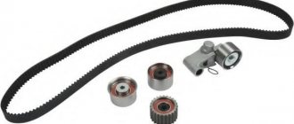
- Timing belt repair kit 038 198 119 A, which includes the timing belt itself, tensioner roller, idler pulley and a pair of new nuts for the rollers.
- One (preferably two) extra set of new roller nuts 038 109 454 A and N 01508315 just in case. The fact is that the tensioner pulley nut from the repair kit was an obvious factory defect, and even packaged in a neat plastic bag. According to the law of meanness, this was discovered when it was already too late.
- New pump 045 121 011 H.
- New bolts N 90945002 (3 pcs) securing the pump to the cylinder block (BC) just in case.
- Liter of concentrate G12++ G 012 A8G M1.
- Distilled water, 1.5 2 l.
- New bolts for fastening the support elements to the engine N 10666601 (2 pieces) and N 10655802 (1 piece), to the spar N 91029602 and N 90596906 (2 pieces) and to each other N 10552402 (2 pieces).
- A locking pin (a drill of a suitable diameter will do) for fixing the camshaft (CV). See text about diameter and required length.
- Bolts N 10303607 (4 pcs) for fastening the poly V-belt pulley to the gear wheel on the crankshaft (CV).
- Device for holding a gear wheel on the RV. See photo 65 in the text.
- Screw jacks or similar devices for supporting the engine. See photos 33-35 in the text.
- Crankshaft stopper (CV) T10050.
It is necessary to especially note the importance of the HF stopper. Without it, in my opinion, it is almost impossible to correctly install the timing belt!
The work can be done entirely alone, but it is better to have an assistant, especially at the assembly stage. Having a second pair of arms, and legs too, turns out to be very useful.
Now let's talk about doing the work in detail.
1. I did the work in the garage in the inspection pit. It is better to drive in so that the right wheel is as close as possible to the edge of the hole - it will be more convenient to work with the tool at the HF.
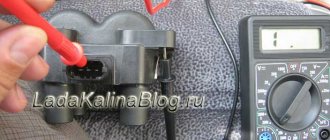
2. Before starting disassembly, I recommend checking that there are no faults in the memory and the values of the measuring groups of the engine ECU with the old belt in order to eliminate possible speculation after installing a new one.
VCDS Version: Release 805.4 Data version: 20090602
Monday,27,September,2010,14:30:07:01327
Chassis Type: 1K0 Scan: 01 03 08 09 15 16 17 19 25 42 44 46 52 62 72 76 7D
VIN: WAUZZZ8P66A123456 Mileage: 120980km/75173miles
00-Steering Angle Sensor - Status: OK 0000 01-Engine - Status: OK 0000 03-ABS Brakes - Status: OK 0000 08-Auto HVAC - Status: OK 0000 09-Cent. Elect. — Status: OK 0000 15-Airbags — Status: OK 0000 16-Steering wheel — Status: OK 0000 17-Instruments — Status: OK 0000 19-CAN Gateway — Status: OK 0000 25-Immobilizer — Status: OK 0000 42-Door Elect, Driver - Status: OK 0000 44-Steering Assist - Status: OK 0000 46-Central Conv. — Status: OK 0000 52-Door Elect, Pass. — Status: OK 0000 62-Door,Rear Left — Status: OK 0000 72-Door, Rear Right — Status: OK 0000 76-Park Assist — Status: OK 0000 7D-Aux. Heat — Status: OK 0000 ——————————————————————————— Address 01: Engine Labels: 03G-906-016-BKC.lbl Part No SW: 03G 906 016 CC HW: 028 101 183 2 Component: R4 1.9L EDC G000SG 6231 Revision: 12345678 Serial number: 01234567890123 Coding: 0000071 Shop #: WSC 06314 000 00000
No fault code found. Readiness: 0 0 0 0 0
It is also worth making sure that the ECU has completed all test procedures (Readiness = 00000). Otherwise, the absence of fault codes in the memory does not mean anything; The fault codes may have been erased relatively recently.
I would like to note that for the last six months (15 tkm), the synchronization of the RV and HF was -0.5 degrees and did not depend on the temperature or engine speed. During the first 4.5 years it was always 0. Perhaps during operation the belt stretches a little, which causes a slight desynchronization of the shafts.
3. Having driven into the garage to the pit, it is necessary to allow the engine to cool completely if it is hot, so as not to get thermal burns and to correctly set the tension of the new timing belt. While the engine is cooling, remove and clean the plastic noise and dirt protection from below. You will need a T25 bit.
4. Put the car on a jack and remove the front right wheel. Be sure to put the car on the handbrake and securely block the front left wheel with wheel chocks to completely prevent the car from falling off the jack while doing work.
5. Partially remove the front right wheel locker and move it into the wheel arch to ensure easy access to the wheel arch - you will need to remove several screws in the wheel arch and below the bumper using a T25 bit.
Be prepared for the fact that a lot of road dirt and sand may spill out of the locker. I had to do a little cleaning before continuing.
6. Using a lint-free rag, remove dirt and dust from engine parts and air ducts around the timing belt guard.
7. Remove the fasteners from the fuel filter mounting flange. You will need a 10 mm socket and a long extension, or a pair of extensions inserted into each other.
8. Using a soft pencil, mark the working direction of the poly-V-belt, so that later we can put it the way it was if the belt is not replaced with a new one.
9. Lock the automatic tensioner of the poly V-belt. To do this, use a 16 mm open-end wrench to turn the movable part of the tensioner clockwise so that the locking pin can be inserted. I used a 4 mm L-shaped 6-point key as a locking pin. An iron nail of the appropriate diameter and length may also work.
10. Remove the poly V-belt and carefully inspect its condition. We decide whether replacement is necessary.
It would also be a good idea to check the condition of the bearings and overrunning clutch of the generator with the poly V-belt removed.
11. Remove the poly V-belt pulley from the HF. To do this, I engaged 4th gear and blocked the hub bolt of the removed wheel by installing a 27 mm socket wrench on it and resting it on the floor. A 24mm hex socket may be needed if the hub bolt is a different type (see [email protected] ). We unscrew the 4 bolts securing the pulley to the KV gear. You will need a bit with a 6 mm hexagonal insert.
12. Remove the lower part of the timing belt guard. You will need a 10mm socket.
13. Open the locks and remove the air duct section. Be prepared that there may be some engine oil inside that may spill out when the section is removed. You should prevent engine oil from getting on the cooling system hoses by placing a rag under the detachable joints of the air duct.
We cover the air duct with a lint-free rag so that nothing gets inside while the work is being done.
14. Remove the plastic part of the timing belt casing - open 2 spring-type latches and remove the casing.
15. Turn the engine clockwise to install the HF stopper. At the same time, we monitor the RV gear so that it is in the position where the window with the teeth is on top.
It doesn't take much effort to crank the engine if you don't try to crank it quickly. I cranked the engine by applying force to the head of the hub bolt with 4th gear engaged. In my opinion this is the most convenient way.
The HF stopper can be of two types, and you need to find out which one is needed: T10050 or T10100. In my case - T10050.
The CV stopper should be installed on the CV gear, sliding it from the end so that the marks on the CV and the stopper coincide. The stopper fits into place very accurately. On the first try, you may not be able to install it; in this case, you should turn the HF further clockwise 2 times. The CV stopper must enter the counter hole in the cylinder block (BC) and completely “sit” on the CV gear.
16. Having installed the HF stopper, we will now block the RF. To do this, it is necessary to insert the locking pin into the hole in the head of the BC through the gear wheel and its hub on the RV. As a pin I used a drill with a diameter of 5.84 mm; a drill with a diameter of 5.95 mm did not fit (the diameters of the drills were measured with a micrometer). The drill enters 61 mm from the plane of the gear wheel РВ.
17. By this time, my engine had completely cooled down. Out of curiosity, I checked the position of the indicator of the old tensioner pulley with the old timing belt.
18. Drain the coolant. Use a lint-free rag to clean everything around the oil cooler. Use small pliers to squeeze and slide the clamp onto the hose. It is better to use a special clamp tool. If it is not there, then you will have to suffer a little.
Under the oil radiator we place a funnel made from the neck of a clean 2-liter plastic bottle, and under the funnel - a clean plastic 6-liter jar to collect the drained coolant.
Open the cap of the expansion tank. Slowly pull off the cooling system hose from the oil radiator and drain the coolant, bleeding it slowly. I have glass from the cooling system of approximately 2.5 3 liters. You can also try to disconnect the cooling system at the small tee. Perhaps then it will be possible to drain more and minimize coolant losses as much as possible.
Drain the coolant, put on the hose and put the clamp in place.
19. Remove the tensioner roller for the poly V-belt - 6-sided socket head 13 mm. Check the condition of the roller bearing.
20. Remove the electrical connector and the fastening of the expansion tank - 2 self-tapping screws. You will need a cross-shaped bat.
21. Using a soft pencil, mark the position of the engine support elements relative to each other and on the right side member to facilitate reassembly.
22. We hang the engine on a traverse, or place screw jacks under the engine and gearbox. I used the second option.
23. We slightly lower the jack under the right threshold to relieve the bolts securing the 2 engine support elements to each other and to prevent damage to the threads in the element made of aluminum alloy.
24. Unscrew the 2 bolts holding together the 2 elements of the engine support - 6-sided 18 mm socket head.
25. Raise the jack slightly under the right threshold to remove the load from the place where the parts of the engine support come into contact with each other.
26. Remove the engine support element from the right side member - unscrew 4 bolts - 6-sided socket head 13 mm and 16 mm.
27. Remove the engine support element from the cylinder block - 3 bolts, 16 mm hexagonal socket head.
Access to one bolt is very limited. I had to get a little tricky to get to it with a tool: I used a torque wrench with a replaceable attachment and shortened the length of the socket head as much as possible, cutting it off at both ends on a lathe. After removing the support element from the BC, it is advisable to go through the thread with a tap.
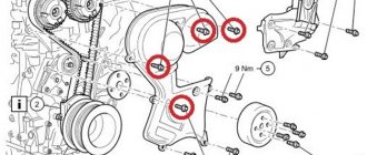
28. Remove the middle part of the timing belt protective casing - 10 mm socket. We have a view of the timing belt, tensioner roller (upper roller), idler roller (lower) and pump. As you can already see in the previous photos, my pump was leaking. Next I will write in detail about the condition of the pump.
29. Mark the working direction of the timing belt with a soft pencil if you plan to put it back or just in case.
30. Before continuing to disassemble, I recommend studying the operation of the tensioner roller with an eccentric.
We loosen the bolts securing the gear wheel to the RV hub by 1-2 turns - 6-sided socket head 13 mm.
We loosen the nut securing the tensioner roller - a 6-sided socket head or a 15 mm socket wrench. Using a 6 mm L-shaped hex wrench, turn the tensioner roller eccentric counterclockwise so that you can insert the locking pin, for example a 1.5 mm L-shaped hex key. Turn the eccentric clockwise until it stops and lightly tighten the nut. You should pay attention to the movement of the tensioner roller: the blocked tensioner roller moves down and the tension is removed from the timing belt.
Again, loosen the nut and turn the eccentric counterclockwise until the locking roller pin can be easily removed. If you now turn the eccentric clockwise, the tensioner roller will tension the timing belt.
(I hope my memory serves me correctly and I remember correctly about the eccentric).
31. Remove the bypass roller, having first unscrewed the nut - 6-sided socket head 13 mm. We check the condition of the bearing. My old deflection roller had noticeable play.
32. We carry out the procedure for relieving the tension of the toothed belt, see paragraph 30. If necessary, loosen the bolts securing the gear to the hub RV by 1-2 turns - a 6-sided socket head, or a 13 mm socket wrench. Remove the timing belt. Let's examine his condition.
33. Remove the old tensioner roller and inspect it. My old tensioner roller had noticeable play and rotated quite “dry” compared to the new one.
34. Clean and wash from dirt and dust, as well as coolant leaks inside the toothed belt casing.
35. Unscrew the 3 bolts securing the pump to the BC - 10 mm socket head.
36. Grabbing the “leg” with pliers, carefully lift the pump from its seat in the BC and hold it with your hand.
37. With your free hand, press rags or paper towels under the pump and slowly bleed off the remaining coolant in the cooling system, moving the pump in the BC. After some time, the coolant stops leaking.
38. Carefully remove the pump from the BC and inspect it. My pump was leaking, its bearing turning with the creaking sound of an old door. The impeller was in perfect order.
So I think that the specified interval for replacing the timing belt of 120 tkm is the machinations of VAG’s koekak managers and marketers, and nothing more! In practice, the interval must be reduced, for example to the previous 90 tkm.
I would like to note that the creaking of the pump bearing was clearly audible when cranking the engine by hand. If there are no defects in the roller bearings and pump, the engine turns silently. You can only hear how the air compressed in the cylinders makes a “zilch” at the moment the exhaust valves open.
39. We wash and clean the pump installation site. When cleaning the surface of a BC, a razor blade can be very useful. I advise you to tighten the pump mounting bolts so that dirt does not get into the threaded holes.
40. Carefully install the new pump in the BC, moistening the O-ring with G12++ concentrate. The tightening torque of the bolts securing the pump to the BC is 15 Nm, 6-sided socket head 10 mm. Make sure there is no liquid in the bolt holes to avoid damage!
The new pump came to me with the number on the body 045 121 019 D
the old one had 045 121 019
C. This means that the part has been modified. I would like to hope that it has been modified for the better...
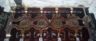
41. We check the condition of the gear wheels on the RV and KV. They must be replaced if there is visible wear. In my case, replacement was not required.
42. Mark the new tensioner pulley nut to make it easier to make the final 45 degree turn.
43. Install the new tensioner roller on the corresponding pin and make sure that its leg fits into the counter window in the BC. The roller must be completely adjacent to the BC with its base. The new tensioner roller should also be checked for defects, play and ease of rotation.
The new tensioner roller in the repair kit is already locked with a pin. Therefore, we simply turn the eccentric clockwise until it stops, similar to the procedure for relieving belt tension (see paragraph 30), and lightly tighten the nut. In this position, the tensioner roller is as far away from the timing belt as possible.
44. Turn the gear wheel on the RV hub by hand clockwise almost all the way. This is done so that the timing belt can carry the gear counterclockwise with it when we tighten the belt using the tensioner roller.
45. Install a new timing belt. It seemed convenient to me to start with the CV, then the tensioner roller and the PV gear, and finally the pump. The uninstalled idler pulley (bottom) makes it relatively easy to install a new timing belt.
46. After the new timing belt is installed, visually check that the gear can turn counterclockwise!
47. Install the new idler roller on the corresponding stud. The roller should “sit down” to the end and its end should be adjacent to the BC, rotate easily and have no play. The tightening torque of the nut is 22 Nm, 6-point socket head 13 mm.
48. Loosen the tensioner roller nut. Using a 6mm L-shaped 6-point wrench, rotate the tensioner roller eccentric counterclockwise so that the locking pin can be easily removed.
Having removed the locking pin, rotate the eccentric clockwise and watch the tensioner roller indicator. When the indicator is in the middle of the cutout, tighten the nut to a torque of 20 Nm.
When tensioning the toothed belt, you should also monitor the toothed wheel RV, which should, following the toothed belt, rotate 1-2 teeth counterclockwise. In this case, the hole in the RV hub should be located approximately in the middle of the window with teeth.
When performing this operation, it is worth remembering the phenomenon of parallax: the tension roller indicator may appear to be in the middle of the cutout without actually being there. Therefore, choose the right viewing angle!
Having an assistant is desirable and makes the operation easier.
The last photo was taken later. It shows the position of the toothed window and the hole in the RV hub after tensioning the toothed belt with a tensioner roller
49. Tighten the gear wheel mounting bolts on the hub RV in several passes to avoid distortion, holding the gear wheel with a special tool. Tightening torque - 25 Nm, 6-point socket head 13 mm.
50. Remove the stoppers RV and KV.
51. Manually turn the crankshaft 2 times.
52. Install the HF stopper.
53. We make sure that the PB stopper can also be installed, i.e. RF and HF synchronization is ok.
54. You can remove the stoppers and crank the engine a few more times. Then make sure that the stoppers can be installed, i.e. synchronization between radio and shortwave signals does not go away.
55. Transfer one mark from the tensioner roller nut to the eccentric.
56. Holding the eccentric with an L-shaped 6-sided 6 mm wrench, turn the nut clockwise 45 degrees until the second mark on the nut aligns with the mark on the eccentric. It is allowed that the indicator can move up to 5 mm clockwise.
57. Install the middle part of the timing belt protective cover - 6-sided socket head 10 mm, bolt tightening torque - 10 Nm. We do not install the bottom 2 bolts yet.
58. Install part of the engine mount on the BC. The bolts must be replaced with new ones. It is recommended to lubricate the threads with engine oil.
Having studied materials on the Internet and consulted with experts, I settled on a tightening torque of 40 Nm + 90 degree rotation; 6-point socket head 16 mm.
59. We install part of the engine support on the right side member according to the marks made. The bolts are similarly replaced with new ones, the threads are lubricated with engine oil. Tightening torque - 40 Nm + additional 90 degrees. Don’t forget to install the jumper from the support body to the right wing, torque – 20 Nm.
60. Lower the jack under the right threshold so as to align the two elements of the engine support. Having lubricated the threads of the new bolts with engine oil, we fasten the support elements to each other, torque - 60 Nm + additional rotation of 90 degrees; 6-sided socket head 18 mm.
In the center of the support, when viewed from above, there is a blind hole that can be used to align the support elements with each other by inserting a long pin into it. A large flathead screwdriver is also a good way to align the support elements relative to each other.
The assistant's second pair of hands turns out to be very useful for performing this operation.
61. We put the expansion tank in place - two self-tapping screws.
62. Replace the lower part of the toothed belt guard. Please note that the lower part of the casing is tucked under the middle one.
63. We install the poly V-belt pulley on the HF. The bolts must be replaced with new ones, torque - 10 Nm + additional rotation of 45 degrees.
In this operation, an assistant can again be very useful, engaging 4th gear and pressing the brake pedal so that you can easily tighten and screw the bolts into the CV gear.
Pay attention to the key for correct installation of the pulley on the KV gear.
64. Reinstall the poly V-belt tensioner, torque - 23 Nm; 6-point socket head 13 mm.
65. Install the poly V-belt and unlock its tensioner. If an old poly V-belt is installed, then we install it according to the marks made, maintaining the same working direction.
66. Install the plastic timing belt protective cover.
67. Install the air duct section and close the locks.
68. Install the fuel filter flange, torque - 10 Nm.
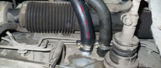
69. Fill the drained coolant into the expansion tank. In order for the liquid to begin to fill the cooling system, you need to remove the hose from the small tee, see photo.
70. Prepare coolant from distilled water and G12++ concentrate, using measuring cups to compensate for losses. The proportion of mixing the concentrate with distilled water is given on the label.
71. We start the engine and check the synchronization of the RV and KV in the ECU. I immediately got 0.
72. Check the coolant level and top it up as air leaves the cooling system. To expel the air faster, you can hold the speed at about 2000 rpm for a minute or two.
73. Close the expansion tank cap. 74. Install the locker fasteners. 75. Install the front right wheel on the hub - torque 120 Nm, 6-sided socket 17 mm. 76. Make a test drive and add coolant as needed. 77. Inspect the timing belt, the position of the tensioner pulley indicator (on a cold engine), and the coolant level in the expansion tank.
When is it necessary to replace the timing belt?
The timing for each model is regulated by the manufacturer: the frequency is indicated in the manuals. But the quality of the roads and driving style correct this parameter: it is better to replace the timing belt on the Passat B3 after 60,000 km on the speedometer.
If the mileage is low, but the car is already five years old, the spare part is replaced. At this point, cracks, abrasions, and delamination may form. Displacement, sagging, and slippage of the product also occur, which leads to problems with the power plant. One of the reasons for the replacement was that the timing teeth were cut off on the crankshaft. However, this problem affects engines with low camshafts.
If the timing belt breaks on the Passat B3, then the connection between the shafts is lost. By inertia, they will still rotate even when the engine has stalled - the pistons will begin to move chaotically up and down, opening/closing valves. As a result, the piston will go up, the valves, due to the lower inertia of the camshaft, will get stuck in an incorrect position and may collide with the piston. The engine stalls: then you cannot do without engine repair.
Belt life
If you do not monitor the state of the transmission, it may well break off. Do not allow this to happen under any circumstances, as a broken belt is fraught with quite serious consequences. Most likely, in this case the pistons will hit the valves. The consequence of this will be deformation of the valves. Other parts may also receive various damages. Here everything will depend on the degree of luck. If the valves are bent, then the car will have to be seriously repaired. That’s why it’s better to look under the hood more often, so that later you don’t have to pay for your laziness.
The belt drive should be replaced if the following defects are noticed on the belt:
- cracks on the surface;
- partial wear of teeth;
- bulges;
- delamination of the material structure;
- presence of oil stains on the surface.
The belt can work properly for 90,000 km. But this regulation is quite conditional, since wear of the belt drive may occur a little earlier. A number of reasons may contribute to this. If you operate your car primarily in extreme weather conditions, this will certainly affect premature wear of the drive. Increased loads on the motor system will also contribute to this. For example, if you use a trailer, this will definitely create an increased load on the engine. Driving over potholes will have the same consequences.
Separately, I would like to say about the contact of working fluids with the drive surface. The belt is made of high quality rubber. But this material also ages over time. And motor oil can generally kill it in a short time. Oil corrodes rubber, so a belt with oil stains must be replaced.
The presence of leaks indicates that depressurization has occurred and it is time to replace the seals. When visually inspecting the condition of the timing belt, you need to pay attention to the tension roller. This consumable can also fail. This can be detected by the presence of play on it. It is worth checking the condition of the additional rollers and replacing them if necessary.
Buy consumables only from trusted dealers. On the market they may very well sell you a fake that will wear out very quickly. Here's how you can distinguish a branded belt from a fake: ask the seller to show you several belts. Look at their numbers located on the inside. The numbers on branded consumables are always different, but fakes are usually numbered the same.
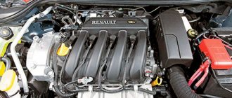
Timing belt selection
The third generation VW Passat sedan was released in 1988. The engines ran on gasoline and diesel. Suggested volumes: 1.6, 1.8, 1.9, 2.0 and 2.8 liters. Transmission: five-speed manual, four-speed automatic.
Most Volkswagen Passat B3 models used a timing belt. The chain drive was only available on the AAA (VR6) engine model with single injection.
Drivers select timing belts according to engine types. Originals and analogues with articles and prices:
- AAM, ABS, ABN, RP, RF, EZ, 1F, DZ – VAG No. 056 109 119 A. Similar belt Contitech CT637. 121 teeth Discounted price - 407 rubles.
- 2E, ACX – VAG No. 037 109 119 C. Can be replaced with Contitech CT 630. 124 teeth. Discounted price - 501 rub.
- 1Y AAZ – VAG No. 028 109 119 P. Similar element to Contitech CT 867. 137 teeth. Price — 1318 rub.
- SB – VAG No. 068 109 119 E. Replaced with Contitech CT 513 belt. 135 teeth. Price — 761 rub.
New timing belt for Passat B3
Best manufacturers:
- Gates is a Belgian company that produces all drive belts and supplies products directly to the assembly shops of automobile factories around the world.
- Contitech - elements of gas distribution mechanisms and air suspension; other components of the German company are also stock in popular car brands. The second well-known manufacturer from Germany is Bosch.
- Dayco - Italians supply rollers, bearings, rubber products for various brands of cars from major manufacturers.
For those who are concerned about the safety of their car, it is better to buy and install components from an authorized dealer.
Determining the need for replacement
The official manufacturer states that the resource of the Volkswagen Polo timing chain is designed for the entire service life of the vehicle. Dealers claim that it is necessary to change the elements of the gas distribution mechanism drive when the mileage reaches about 180-200 thousand km.
Experienced car owners recommend replacing the chain at a mileage of 90-120 thousand km. This is not due to the end of its life, but to stretching. As a result, a slight phase shift occurs, causing a drop in power by 20-40 horsepower.
Symptoms of the need to replace the timing chain of a Volkswagen Polo are:
- extraneous knocking noises when the engine is running, coming from under the timing drive casing;
- increased fuel consumption;
- power reduction;
- the engine stalls periodically;
- popping sounds in the intake and exhaust manifolds;
- instability of the engine when cold and under load;
- there are difficulties starting the power unit.
Why are timing marks needed?
On the Passat B3, the timing belt synchronizes the valve timing with the engine strokes. The mechanism connects the shafts and does not allow the simultaneous admission of the air-fuel mixture into the combustion chambers and the release of exhaust gases.
How to ensure that the shafts - camshaft and crankshaft - work precisely synchronously: at the time of the first start after installation/repair of the timing belt, they must start from certain positions. The correct starting position is indicated by special timing marks on the Volkswagen Passat B3.
An incorrect ratio of the marks and an erroneous start of the shafts will lead to a collision of the cylinders with the exhaust valves and engine damage.
Adjusting belt tension
An optimally tensioned belt rotates 90° with a hand force of 1.5-2.0 kg. Your fingers should be placed on the belt between the shaft pulleys (camshaft and crankshaft).
If the part is overtightened, the bearings of the water pump and tension roller wear out; if it is loose, the teeth jump and the part may fly off.
How to adjust tension:
- Motorists rotate the eccentrically located axis (eccentric) counterclockwise with a special wrench or a 7-mm hexagon attachment until the holes on the rod and the tensioner body align, then fix it with a pin.
- Turn the roller in the opposite direction, measuring the gap between the tensioner pusher and the roller. When the indicator is 4 mm, fix the roller and pull the pin out of the tensioner.
- Make 2 turns of the HF, check the marks.
After setting the marks and adjusting the tension, the car is sequentially assembled and returned to its original form.
When is it necessary to install timing marks?
Tags are a crucial moment. They must be aligned relative to each other.
In what cases are labels placed:
- Replacement of the gas distribution mechanism. The shafts must immediately be brought into line with each other.
- Repair of any timing belt assembly, especially with belt removal. The position of the shafts in relation to each other must not be disturbed.
Knowledgeable drivers, as part of their own technical inspection, check whether the indicators match. A simple procedure prevents the motor from going out of working order.
How to correctly set the tags on a Volkswagen Passat B3
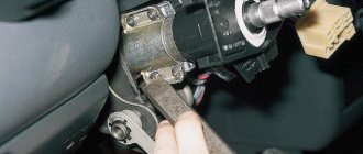
Car owners will need a minimum of tools: a flat-head screwdriver, a wrench with a 10-mm head, and a jack.
Sequencing:
- Disconnect the battery.
- Raise the right front wheel on a jack - access to the “knee” and RV gears is open.
- Remove the protective cover.
- Find the factory marks on the shaft pulley and engine block.
- Rotate the wheel and align the indicators.
- Remove the inspection hole plug on the clutch bell between the engine and gearbox, check whether the marks on the body and on the clutch bell match.
- If the marks do not match, turn the flywheel with a screwdriver until they do.
Timing belts for Passat B3 from different manufacturers
The shafts are exposed, the structure is assembled in order in place. It is important that the belt is tensioned while marking.
What to do if there are no tags
You still need to align the shafts if there are no marks. Drivers use the same tool and additionally take a flat, hard metal rod half a meter long.
Operating procedure:
- Raise the right front wheel with a jack.
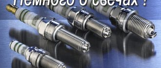
- Unscrew the spark plug in the first cylinder (farthest from the bell), insert a wire into the hole.
- They feel and rest against the “head” of the piston.
- They spin the wheel. At some point it is possible to determine the upper position of the piston.
- They leave him in this position.
When the top dead center of the piston is found, the car is restored to its original form.
An unconventional method: drivers find an identical motor with exposed shafts. Set some guidelines for yourself. Measure the distance between them and transfer them to your motor. You can count the teeth on the belt between different marks.
Instructions for replacing the timing belt on a Volkswagen Passat B3
When the theoretical part has been studied, you can replace the belt with your own hands. The part must be replaced at the same time as the rollers, regardless of the extent to which they are worn.
Indicative for beginners will be replacing the timing belt of the Passat B3 2e digifant with an engine capacity of 2 liters.
Required parts and tools
No stands or special equipment is required. Buy a strap and a tension roller.
Tools and accessories:
- jack;
- stand under the car body (a spare tire or an unnecessary wheel rim will do);
- supports for the rear wheels (chocks);
- screwdrivers;
- set of wrenches.
For ease of work, first dismantle the Digifant air filter housing. It is located in the engine compartment.
The car is disconnected from the battery, placed on a jack, wheel chocks are placed under the rear wheels, and a support is placed under the body.
Removing the Belt Guard
Next, remove the air duct corrugation, power steering (power steering) belts, generator and pump. An arrow indicating the direction of rotation is drawn on the removed straps with a marker.
The upper part of the casing is removed by unscrewing the 2 retaining bolts and unlatching the latches. Auto mechanics unscrew the lower casing with a socket set to “10” and a hex wrench to “5”.
The video shows how to remove the timing belt protection for the Passat B3:
Operating procedure
When the preparatory work is completed, drivers change the element. The order is:
- The piston of the first cylinder is set to top dead center so that the marks coincide.
- Mark with a marker the position of the shaft gears, crankshaft and camshaft.
- Use a hexagon to “6” to unscrew the 4 fasteners of the KV pulleys. The “knee” is locked to prevent it from turning. To do this, you need to engage fifth gear, tighten the handbrake, and an assistant must press the brake pedal. Another way is to pull out the plug in the flywheel rotation zone and lock the shaft through the hole by inserting a powerful screwdriver or pry bar.
- Using a wrench with a “15” head, unscrew the tension roller bolt, first loosen it, then remove the part from the engine.
- Remove the tensioner roller and install a new one.
- Check how the labels are installed.
Then all the work is done in reverse order. When the machine is assembled, turn the bolt on the KV pulley two full turns, and once again check that the marks match. How to change the timing belt is shown in the video:
The procedure for replacing timing belts is also applicable to other modifications of the Passat B3 - Drive 2 and Mono - for 1.8-liter engines with injectors.
Addition:
At the beginning of the report there were photos of original VW belts and rollers that we selected for replacement.
Many people cannot afford this kit, so owners are looking for an alternative to an expensive kit from less famous but high-quality manufacturers.
More recently, such a kit appeared on sale from INA. The equipment, quality and price are excellent.
Practice has shown that all the parts from the kit work perfectly and reliably cover a mileage of 60 thousand km. Our price for this kit is 90-100 euros, which is again cheaper than buying parts individually.
See photos and equipment below:
I wish you a successful timing belt replacement.
If you have not found information on your car, look at the cars built on the platform of your car. Most likely, the information on repair and maintenance will be suitable for your car.
5-cylinder petrol engine
1. Place the machine on supports.
2. Remove the lower engine compartment cover.
3. Remove the machine from the supports.
4. Remove the V-belt.
5. Set the crankshaft to the TDC position for the first cylinder. Rotate the crankshaft clockwise.
6. The crankshaft is at TDC if the mark on the camshaft gear coincides with the mark on the rear timing belt guard.
7. At the same time, the mark on the flywheel or clutch driven disc must coincide with the TDC mark. The illustration shows both corresponding marks on the vibration damper and on the timing belt guard. These marks are used to adjust TDC when the engine is removed.
8. Remove the upper timing belt guard. Using a felt-tip pen or grease pencil, mark an arrow on the belt in the direction of its movement. The engine rotates, when viewed from the front, clockwise to the right.
9. Loosen the timing belt.
10. Unscrew the vibration damper from the crankshaft timing belt gear by unscrewing 4 M8 bolts.
11. Remove the toothed belt.
The toothed belt must not have cuts. A toothed belt with cuts must always be replaced, as it can break during operation, which will lead to severe damage to the engine.
12. If possible, do not change the position of the toothed belt gears.
1. Place the timing belt on the crankshaft gear, idler roller and water pump.
2. Screw the vibration damper with 4 bolts with a torque of 20 Nm.
3. Screw on the lower toothed belt guard. Otherwise, rotate the camshaft so that the mark on the camshaft drive gear aligns with the upper edge of the cylinder head cover gasket.
If the camshaft rotates with the timing belt removed, then not a single piston should be at TDC. Otherwise, severe damage to the pistons or valves may occur.
If you need to rotate the camshaft, first set all pistons to the same height. To do this, apply a chalk mark on top of the crankshaft belt pulley (precondition: the crankshaft is in the TDC position for cylinder 1), then turn the crankshaft belt pulley 1/4 turn (90°) to the left or right, guided by the chalk mark.
4. Check the position of the crankshaft at TDC for the 1st cylinder. Through the inspection hole of the clutch housing, the TDC (0) mark on the flywheel should be visible, standing exactly next to the installation edge.
5. If the timing belt will be installed on a removed engine, the notch on the belt pulley must coincide with the timing mark on the cylinder head cover. In this case, the crankshaft is in the TDC position for cylinder 1.
6. Put on the timing belt.
When installing the timing belt, the position of the camshaft and crankshaft must not be changed. Otherwise, the engine may suffer severe damage or may not develop full power. After tensioning the timing belt, check the position of the camshaft and crankshaft again. This means: if the mark on the camshaft gear coincides with the upper edge of the cylinder head cover gasket, then at the same time the TDC mark on the flywheel must coincide with the corresponding mark. Otherwise, repeat the adjustment of the camshaft drive gear and crankshaft gear.
7. Tension the toothed belt.
8. Turn the crankshaft 2 turns in the direction of its rotation and check the adjustment and tension again.
9. Install the upper timing belt guard.