Design. Fuel rail, injectors, injection pump.
Fuel rail
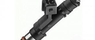
On the first engine with direct injection, the designers used collapsible low-resistance injectors controlled by a high-voltage driver. The fuel rail has a 2-story design of different diameters. This is necessary to equalize the pressure. The following photo shows the high pressure fuel cells of the 3S-FSE engine. Fuel rail, fuel pressure sensor on it, emergency pressure relief valve, injectors, high pressure fuel pump and main pipes. In engines with direct injection, the operation of the first pump is not limited to 3.0 kilograms. Here the pressure is slightly higher, about 4.0-4.5 kg, to ensure adequate power supply to the injection pump in all operating modes. Pressure measurement during diagnostics can be done with a pressure gauge through the inlet port directly on the injection pump
When starting the engine, the pressure must “build up” to its peak within 2-3 seconds, otherwise the start-up will be long or not at all. If the pressure exceeds 6 kg, then inevitably the engine will be very difficult to start when hot. While moving, the engine will inevitably “stumble”, stumble upon sudden accelerations. The photo measures the pressure of the first pump on the 3S-FSE engine (the pressure is below normal, the first pump needs to be replaced.) If the pressure is above 4.5 kg, then you need to pay attention to the clogging of the mesh at the injection pump inlet. Or to the jamming of the pressure pump return valve in the injection pump. The valve is removed from the pump and washed using ultrasound. The photo shows the return valve and its installation location in the injection pump.
After cleaning the mesh or repairing the return valve, the pressure becomes correct.
Since the engines were produced for the Japanese domestic market, the degree of fuel purification does not differ from conventional engines. The first screen is the mesh in front of the pump in the fuel tank.
Then the second fine filter filter is the engine (3S-FSE) (by the way, it does not retain water). When replacing the filter, there are often cases of incorrect assembly of the fuel cassette. This results in a loss of pressure and non-starting.
This is what the fuel filter looks like in cross-section after 15 thousand mileage. A very decent barrier to gasoline debris. If the filter is dirty, the transition to lean mode either takes a very long time or does not occur at all.
And the last fuel filtration barrier is a mesh at the injection pump inlet. From the first pump, fuel with a pressure of approximately 4 kg enters the injection pump, then the pressure rises to 120 kg and enters the fuel rail to the injectors. The control unit evaluates the pressure based on the signal from the pressure sensor. The ECM adjusts the pressure using the regulator valve on the injection pump. In the event of an emergency increase in pressure, the pressure reducing valve in the rail is activated. This is how the fuel system on the engine is briefly organized. Now let’s learn more about the components of the system and methods of diagnosis and testing.
High pressure fuel pump (HFP)
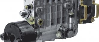
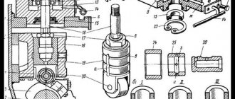
The high pressure fuel pump has a fairly simple design. The reliability and durability of the pump depend (like many things in the Japanese) on various small factors, in particular on the strength of the rubber seal and the mechanical strength of the pressure valves and plunger. The structure of the pump is common and very simple. There are no revolutionary solutions in the design. The basis is a plunger pair, an oil seal separating gasoline and oil, pressure valves and an electromagnetic pressure regulator. The main link in the pump is a 7mm plunger. As a rule, the plunger does not wear out much in the working part (unless, of course, abrasive gasoline is used.) The main problem in the pump is the wear of the rubber seal (the lifespan of which is determined to be no more than 100 thousand kilometers). This resource, of course, underestimates the reliability of the engine. The pump itself costs an insane amount of 20-25 thousand rubles (Far East). On 3S-FSE engines, three different fuel injection pumps were used, one with an overhead pressure regulator valve and two with a side valve. Below are photographs of the pump and its component parts.
Disassembled pump, 3S-FSE engine, pressure valves, pressure regulator, oil seal and plunger, oil seal seat.
When operating on low-quality fuel, corrosion of pump parts occurs, which leads to accelerated wear and loss of pressure. The photo shows signs of wear in the pressure valve core and plunger thrust washer.
Before assembling the fuel pump, all elements should be washed in clean diesel fuel and then wiped with a lint-free cloth or dried in a stream of compressed air. When assembling, avoid touching the working surfaces of the plunger pair and discharge valves with your fingers. When assembling, ensure that the work area is clean, wash your hands thoroughly before starting assembly, and repeat this procedure during assembly if necessary. Particular cleanliness when assembling the fuel pump is a mandatory requirement.
Install the working elements of the fuel priming pump (ring, rotor with blades and cover) onto the mandrel (Fig. 163). Pay attention to the location of the ring holes: on side A the distance from the hole to the edge of the ring (I) is greater than on side B (t). Holding the mandrel in a vertical position, carefully insert it into the pump housing (Fig. 164). Pay attention to the installation orientation as it varies from pump to pump. The ring located on top of the mandrel has holes for bolts located at different distances from the inner edge of the ring. Direction of rotation of the fuel pump rotor m.b. right or left, which can be determined by the factory label on the pump body by the presence of the designation R (right) or L (left).
For a pump with a right rotation of the rotor, the elements of the fuel priming pump must be installed in such a way that the side with the smaller distance between the hole and the inner edge of the ring is directed towards attaching the manufacturer's label of the pump (see Fig. 164), for a pump with a left rotation of the rotor towards the label The side with the larger distance between the hole and the inner edge of the ring should be facing. Turn the pump housing over, remove the mandrel and check the position of the elements. For a pump with a right rotation of the rotor (the description is given only for it), the position of the elements must correspond to Fig. 165 (pay attention to the location of the blades). Screw in and tighten the screws securing the elements (Fig. 165).
Install the key into the recess of the drive shaft of the fuel pump, then install the shaft into the pump housing so that the key fits into the groove of the pump rotor (Fig. 166). Place the rollers into the grooves of the support ring and install the support ring with the rollers into the housing (Fig. 167). Turn the support ring with rollers to a position in which the holes for the sliding adjusting pin are aligned (Fig. 168), install the slider in the timer piston and install the piston in the body so that the exit of the piston with a concave profile is directed outward, and the central hole is in the piston , located perpendicular to the slider, was directed towards the roller support ring (Fig. 169). Install the sliding adjusting pin and secure it with a clamp secured with a special pin (Fig. 170).
Install the remaining elements of the timer: servo valve (4), snap ring (3), spring (2), adjusting washer (1) (Fig. 171). It is recommended to use 0.6mm shims and install at least one shim on each side of the spring. Install the timer covers with sealing rings (7) on both sides of the housing and secure them with bolts (see Fig. 171). Install the control valve (1) of the fuel priming pump with sealing rings and tighten it with a tightening torque within 1 Nm (Fig. 172). Install the driven coupling (Fig. 173), observing the installation orientation: concave plane of the coupling. directed upwards. Before installing the plunger with springs, it is necessary to determine the thickness of the adjusting shim under the plunger springs to ensure the required stroke of the plunger. To do this, the plunger assembly is assembled on the distribution head with the installation of all elements without lower shims, the thickness of which must be determined (Fig. 174).
For the assembled unit, the distance between the end of the distributor head bushing and the end of the plunger “T” is specified. For this pump, this value is 6.54-6.74 mm (average value 6.64 mm). To determine the required gasket thickness, measure the actual distance using an indicator by lightly pressing the plunger (enough to select its stroke, but not compress the springs), as shown in Fig. 175 (for example, the measured value is 5.54 mm), and find the required thickness of the adjusting shim, equal to the difference between the specified and measured values (in our example, the required thickness of the adjusting shim A = 6.64 -5.54 = 1.1 mm). The repair kit includes shims with thicknesses (mm): 0.5; 0.8; 1.0; 1.2; 1.5; 1.8; 2.0.
If the calculation results in a value that is not in the series of specified thicknesses, install an adjusting shim with the nearest greater thickness (in our case, 1.2 mm thick). Install shims of the same thickness under both springs. The assembly parameter “T” determines the initial position of the plunger, from which it begins to move when the pump is operating. Next, it is necessary to provide the assembly parameter “K” (Fig. 176), i.e. the distance between the end of the distributor head bushing and the end of the plunger when the plunger is positioned at the end of its stroke.
This parameter is determined by the thickness of the shim between the driven clutch and the cam disk. To determine the required thickness of the gasket, assemble the elements in accordance with Fig. 176, turn the drive shaft to a position in which the plunger is installed in the extreme position, and using an indicator, measure the distance between the ends of the distributor head bushing and the plunger and determine the required thickness, equal to the difference between the measured the value of the “K” value and required by the pump specification. For a given pump, this value d.b. equal to 3.2-3.4 mm (average value 3.3 mm). If, for example, the measured value is 5.8 mm, then the required shim thickness B = 5.8 - 3.3 = 2.5 mm.
The repair kit includes a set of shims with thicknesses from 1.92 to 2.88 at thickness intervals of 0.08 mm. If the obtained value does not correspond to one of the thicknesses of the gaskets supplied in the repair kit, you should take a gasket with the next thicker thickness. In this kit, the thickness of 2.5 mm is between the thicknesses of 2.48 and 2.56 mm, which means that it is necessary to install a gasket with a thickness of 2.56 mm. Install a shim of the selected thickness and repeat the measurement to ensure that the correct shim thickness is selected. Install the driven clutch, spring, cam disk and washer (Fig. 177), then install the regulator lever (Fig. 178). Install a washer, gasket, support element for the plunger springs, and leakage bushing onto the plunger. Install the leakage bushing so that the hole on the end surface of the bushing faces towards the support element for the plunger springs.
Install the plunger springs onto the plunger support element. Refer to Fig. 179. Having carefully pulled out the regulator lever, install the assembled elements into the pump body so that the pin with the spherical end of the regulator lever fits into the hole in the leakage sleeve (Fig. 180), and the groove in the plunger head coincides with the cam disk pin.
Apply grease to the elements installed on the distribution head (O-ring, two support springs of the regulator lever, two guides of the plunger springs, two adjusting shims for the plunger springs selected according to the previously described method, two upper supports of the plunger springs) and Carefully install the distribution head onto the housing (do not drop the installed elements) (Fig. 182).
Check the correct installation of the elements, install and tighten the screws securing the distribution head.
Install the distributor head plug with a new sealing ring and tighten the fastening bolt with a tightening torque of 6.0-8.0 kg-m (Fig. 183). Screw the discharge valves into the holes of the head, tighten them with a tightening torque of 3.5-4.5 kg-m (Fig. 184). Install discharge valves only with new gaskets. Install the weights, washer and bushing of the regulator into the holder of the balancing weights, install the adjusting washer and the centering washer for the holder of the balancing weights onto the regulator shaft (Fig. 185), install the regulator elements into the body and screw in the regulator shaft (Fig. 186) using a special key. For a pump with a right-hand rotor rotation, the regulator shaft has a left-hand thread. Check the amount of protrusion of the regulator shaft (Fig. 187).
The distance shown in the figure between the edge of the shaft and the edge of the housing should be equal to 1.5-2.0 mm. If it does not fit within the specified limit, adjust by rotating the regulator shaft. After completing the adjustment, install the O-ring and lock nut and tighten the nut with a tightening torque of 2.0-3.0 Nm, holding the regulator shaft from turning. Measure the amount of free axial movement of the balance weight holder.
The permissible free play is 0.15-0.35 mm (Fig. 188). If necessary, adjust the stroke by installing an adjusting shim of the required thickness. The repair kit includes shims with thicknesses in the range of 1.05-1.85 mm at thickness intervals of 0.20 mm.
During assembly, it is necessary to ensure the installation distance between the end of the regulator bushing and the spring trigger lever in the regulator control lever (distance “B” in Fig. 189). For testing, a set of special devices is used (Fig. 190): a limiter for setting a fixed position of the control lever, an adapter used instead of the regulator shaft, an indicator and a measuring rod connected to the indicator and passing inside the adapter.
Computer diagnostics of the 3S-FSE engine
When diagnosing an engine, the scanner provides a date for about eighty parameters to assess the condition and analyze the operation of sensors and engine systems. It should be noted that the big drawback in the date of the 3S-FSE was the absence of the “fuel pressure” parameter in the date for assessing the operation. But, despite this, the date is very informative and, if understood correctly, quite accurately reflects the operation of sensors and systems of the engine and automatic transmission. As an example, I will give fragments of the correct date and several fragments of the date with problems with the 3S-FSE motor. On the date fragment we see the normal injection time, ignition angle, vacuum, engine speed at idle, engine temperature, air temperature. Throttle position and idle speed indication. From the following picture you can evaluate the fuel trim, the oxygen sensor reading, the vehicle speed, and the position of the EGR motor.
Next, we see the activation of the starter signal (important when starting), the activation of the air conditioner, electrical load, power steering, brake pedal, and automatic transmission position. Then turn on the air conditioning clutch, evaporative emission system valve, VVTi valve, overdrive, solenoids in the automatic transmission. Many parameters are presented to evaluate the operation of the throttle body (electronic throttle)
As can be seen from the date, you can easily evaluate the operation and check the functioning of almost all the main sensors and systems of the engine and automatic transmission. If you line up the date readings, you can quickly assess the condition of the engine and solve the problem of improper operation. The following snippet shows the increased fuel injection timing. The date was received by the DCN-PRO scanner.
And in the next fragment, there is a break in the incoming air temperature sensor (-40 degrees), and an abnormally high injection time (1.4 ms with the standard 0.5-0.6 ms) on a warm engine.
An abnormal correction makes you wary and first check the presence of gasoline in the oil. The control unit adjusts the mixture (-80%).
The most important parameters that fairly fully reflect the condition of the engine are lines with indications of long and short fuel trim; oxygen sensor voltage; vacuum in the intake manifold; engine rotation speed (revolutions); EGR motor position; throttle position in percent; ignition timing and fuel injection timing. To more quickly assess the engine operating mode, lines with these parameters can be lined up on the scanner display. Below in the photo is an example of a fragment of the date of engine operation in normal mode. In this mode, the oxygen sensor switches, the vacuum in the manifold is 30 kPa, the throttle is open at 13%; advance angle 15 degrees. The EGR valve is closed. This arrangement and selection of parameters will save time on checking the engine condition. Here are the main lines with parameters for engine analysis.
And here is the date in the “poor woman” mode. When switching to the lean operating mode, the throttle opens slightly, the EGR opens, the oxygen sensor voltage is about 0, the vacuum is 60 kPa, the advance angle is 23 degrees. This is the lean mode of engine operation.
If the engine is operating correctly, then, subject to certain conditions, the engine control unit programmatically switches the engine to a lean operating mode. The transition occurs when the engine is fully warmed up and only after re-gasping. Many factors determine the process of the engine transitioning to lean mode. When diagnosing, one should take into account the uniformity of fuel pressure, the pressure in the cylinders, the clogging of the intake manifold, and the correct operation of the ignition system.
Adjusting high pressure fuel pumps
Regulation of the injection pump must be carried out on special stands by highly qualified specialists. When adjusting the pump, use the bench injectors or injectors with which the pump was installed on the engine, marking the number of each injector in accordance with the cylinder. Before checking and adjusting the high-pressure pump, all injectors (if engine injectors are used) must be carefully checked and adjusted on a special stand in accordance with the specifications for the given type and model of injectors. After adjusting the pump, each injector should be installed on a cylinder corresponding to the pump section that was adjusted together with that injector.
The overall performance of the plunger pairs of the pump can be assessed using bench injectors adjusted to an injection start pressure exceeding the nominal one. 1,8…2
times. If in this case the pump provides supply, then the plunger pairs are in normal condition.
Cycle feed adjustment
The main adjustment of the fuel pump is to adjust the quantity and uniformity of the cyclic supply at nominal mode. To do this, the injection pump rail (or the dispenser for a single-plunger pump) is installed with a special screw in the nominal flow position. At the nominal rotation speed, the cyclic flow of all sections is measured, monitoring the fuel level in the measuring tubes for each section of the pump.
To control the amount of cyclic flow across pump sections, glass graduated test tubes are used, mounted on a test bench and connected to the outlet fitting of the section, or (in modern stands) on a display that visually displays the cyclic flow across sections of the fuel injection pump being tested. The cyclic flow must comply with the specifications for the pump and be adjusted for the specific engine model.
Deviation by sections (unevenness of supply) is allowed no more than 3…5%
.
Otherwise, for pumps of the 33
(KAMAZ) and 60 (ZIL) series, loosen the fastening of the section housing and turn it, moving the housing lock washer by one or two teeth.
Some pumps (4UTNM, YAZDA, ChTZ) have special clamps for fastening sections, which, if necessary, loosen and correct the cyclic flow by turning the section body.
Adjusting the feed start angle
This angle is checked and adjusted on a bench. In in-line pumps for the first section, and in V-shaped pumps of the series 33
– a momentoscope is installed on the eighth section - a glass tube connected through a rubber pipe to a high-pressure fuel line (
see figure
).
The rack is set to the nominal feed position and by manually rotating the pump shaft (by the injection advance clutch), the momentoscope tube is filled with fuel. By turning the shaft back and then slowly rotating it forward, determine the moment when the fuel surface (meniscus) in the momentoscope tube shakes. The rotation is stopped. In this case, the dial of the stand will show the angle to the axis of symmetry of the plunger drive cam. This angle must be within the specifications for that particular pump. So, for the eighth section of a series 33
(KAMAZ), this angle should be
42...43
˚, and for the first section of 4UTNM pumps -
56
˚.
After checking the first (or eighth) section, the torque scope is installed on the remaining sections according to the order of operation of the engine cylinders. The deviation of injection advance angles by sections should not exceed 20
«.
In order to adjust the advance angle of the start of flow in pumps of the series 33
(KAMAZ) are replacing the pusher heel, which is produced in
18
repair sizes.
In pumps such as UTNM, TN, YAZDA, the plunger pusher screw is moved for these purposes. After adjusting the section, this screw is locked with a lock nut. 1. If the check is carried out with the fuel injection pump installed on the engine, and not during the installation of the latter, disconnect the negative wire from the battery and cover the generator with polyethylene. Remove the injector tubes (see Removing and installing the injection pump, subsection “Removal”, item 12). 2. If you have not already done this, loosen the clamp screw and/or nut and slide its end stop along the fast idle speed drive cable, moving it completely away from the actuator lever on the pump (the fast idle lever should press against the stop) (see Removal , installation and adjustment of the temperature-sensitive fast idle speed sensor). 3. Ensure that the crankshaft locking installation drillings are aligned (see Fixing the crankshaft/camshaft and injection pump to prevent the valves from accidentally coming into contact with the pistons during vehicle maintenance procedures). Remove the locking tool and rotate the shaft back (counterclockwise) approximately a quarter turn. 4. Remove the access screw located between the union connections of the four injector tubes at the rear of the injection pump. After unscrewing the screw, place a suitable drain container under the pump to collect spilled fuel. Wipe away any spills with a clean rag. 5. Screw a special threaded nozzle (Citroen No. 4123-T) into the rear of the pump and secure a dial meter in it (see illustration Dial meter and probe for checking the injection timing on the Bosch injection pump
).
6. Slowly rotate the crankshaft back and forth to determine the moment when the injection pump piston reaches the bottom point of its stroke (BDC). Having achieved the required piston position, reset the meter. 7. Slowly rotate the crankshaft in the normal direction until the locking rod can be inserted again. 8. The reading recorded by the meter must comply with the requirements of the Specifications. Otherwise, loosen the front and rear pump nuts and slowly rotate the pump housing until the meter registers the required value. Once you are satisfied, tighten the pump fasteners securely. 9. Rotate the crankshaft one and three-quarters turns in the normal direction, ensure that the pump piston moves to the BDC position (see paragraph 6) and reset the meter to zero. 10. Slowly rotate the crankshaft until the locking holes are aligned (bringing the engine to the TDC position) and recheck the valve timing. 11. If necessary, loosen the pump fasteners again and repeat the procedures described in paragraphs 8-10. 12. Having achieved a satisfactory result, unscrew the threaded attachment and remove the meter. 13. Replace the access screw (don't forget the sealing washer) and tighten it securely. 14. If the check was carried out during installation of the pump, proceed as described in the section Removing and installing the injection pump. 15. If the pump is installed on the engine, return the injector tubes to their place and tighten the union nuts of their union connections with the required force. Connect the negative cable to the battery and remove air from the power system (see Filling the power system with fuel and removing air pockets from it). Start the engine and adjust the idle speed and the speed to prevent spontaneous shutdown (refer to the Chapter Routine Maintenance). Also adjust the fast idle speed drive cable (see Removing, installing and adjusting the temperature-sensitive fast idle speed sensor).
The high pressure fuel pump (HPFP) is one of the main parts of a diesel engine. It creates high pressure, due to which diesel fuel is injected into the cylinders through injectors. It is responsible for the injection order, thanks to which the engine runs smoothly and evenly. What the injection pump is for and how it works was described in the publication dated August 16, 2014.
Adjusting the fuel injection pump is the first measure to prevent diesel engine malfunction. If the engine begins to “eat” too much fuel or smoke, the first thing to do is check the serviceability of the injectors and adjust the fuel pump. Injectors are cleaned or replaced. But the fuel pump must be adjusted on a special stand. And this should be done regularly. After all, an unadjusted injection pump can seriously complicate the operation of the entire fuel system and lead to damage, the elimination of which will cost more than a relatively inexpensive adjustment at a special stand. If the pump works as required by operating conditions, the diesel engine also works like a clock. Such an engine will not need repairs soon.
You can’t check and adjust the fuel injection pump in a home garage “on your knees”. To do this, you need a special stand equipped with electronic equipment, staffed by experienced, well-trained specialists. There's nothing you can do, you have to pay for it. However, we have to pay for everything in our life. And if you don’t pay, then pay.
Checking and adjusting the injection pump occurs in several stages.
1. The stroke of the TNDV rack is adjusted. In car engines, the accelerator cable is adjusted. This allows you to change the fuel supply to the cylinders in a wide range of modes, as well as at idle.
2. The amount of fuel supplied to the cylinders of a diesel engine at idle is regulated. The adjustment is carried out with a special screw, which is first released, scrolled until the desired idle speed is obtained, and then fixed again with a lock nut.
3. Fuel dosage is adjusted. As the supply of diesel fuel to the cylinders increases, the engine speed should increase. It is desirable that such an increase be direct and proportional.
4. Finally, the operation of the pump at high idle speed is regulated, which will ensure smooth acceleration of the diesel engine and its gradual stop.
Let us repeat once again that it is better and cheaper to adjust the high-pressure fuel pump on special stands, where all engine operating parameters are easily controlled, due to which the adjustment will occur faster and with better quality.
Correct adjustment of the fuel pump will ensure smooth and proper operation of the entire diesel engine.
Adjustment of the plunger pairs to the same stroke value and the same amount of feed, as well as adjustment of the speed controller and injection advance device (clutch) are carried out on a special test stand for high-pressure fuel injection pumps. These stands are equipped with all the necessary measuring devices and a variable speed drive. The repair and test instructions on the test stand, together with the necessary data, contain all the necessary information for repair and service work.
Electronic throttle.
The 3S-FSE engine featured an electronic throttle valve for the first time.
There are several problems associated with the malfunction of this unit. Firstly, when the passage channel is contaminated, the speed of the engine decreases and the engine may stop after re-gassing. Treated by cleaning with carb cleaner. After cleaning, it is necessary to reset the data accumulated by the control unit on the state of the damper by disconnecting the battery. Secondly, failure of the APS and TPS sensors. When replacing the APS, no adjustments are needed, but when replacing the TRS, you will have to tinker. On the website https://forum.autodata.ru, diagnosticians Anton and Arid have already posted their algorithms for adjusting the sensor. But I use the arc method of tuning. I copied the readings of the sensors and thrust bolts from the new block and use this data as a matrix. Next in the photo are the installation marks of the motor drive, deformed by improper installation of the TPS.
Throttle position sensor drive, installation matrix.
Adjusting the fuel injection pump on the engine
The fuel injection pump is synchronized with the engine using timing marks to start injection (closing the channel). These marks are located on the engine and on the fuel injection pump.
Typically, the engine's compression stroke is used as the basis (the reference point for injection timing adjustments, although other possibilities may be used for a particular engine model). In this regard, it is important that the manufacturer's instructions are taken into account. In most cases, the timing mark for closing the channel is located on the engine flywheel, on the V-belt pulley or on the vibration damper. There are several possibilities for adjusting the injection pump and setting the correct value for the start of injection (closing the channel).
- The fuel injection pump is delivered from the factory in a form where its cam shaft is locked in a predetermined position. After installing the injection pump on the engine and strengthening it with bolts, when the crankshaft is in the appropriate position, the cam shaft of the injection pump is released. This well-tested method is inexpensive and is becoming more and more popular.
- The injection pump is equipped with a channel closing indicator at the end of the regulator, which must be aligned with the installation marks when the injection pump is installed on the engine.
- The injection timing advance device (clutch) has a mark for closing the hole, which must be aligned with the mark on the injection pump body. This method is not as accurate as the two described earlier.
- After the fuel injection pump is installed on the engine, a high pressure flow method is used at one of the pump outlets to determine the point (moment) of channel closure (i.e., when the plunger closes the fuel outlet channel). This "wet" method is also being actively replaced by method 1 and 2 described earlier.
Rice. Adjusting the injection pump
Rice. Removing air from the fuel injection system
Air bubbles in the fuel can impair the operation of the fuel injection pump or even make it impossible. In this regard, devices that are installed for the first time or are temporarily disconnected must be freed from air.
If the fuel priming pump is equipped with a hand pump, then it is used to fill the line, fuel filter and injection pump with fuel. In this case, the ventilation screws (1) on the filter cover and on the fuel injection pump must remain open until the escaping fuel contains no bubbles. Bleeding must be done every time the fuel filter is replaced or any work is done on the system.
During real-life operation, air is removed from the injection system automatically through the flow valve (2) on the fuel filter (continuous ventilation). A restrictor can be used instead of a valve if the pump does not have a flow valve.
Rice. Injection pump lubrication
It is best to connect the injection pump and regulator to the engine lubrication system, because With this form of lubrication, the injection pump remains maintenance-free. Filtered engine oil is supplied to the injection pump and regulator through the discharge line and the inlet channel through the roller tappet hole or using a special oil supply valve. In the case of a base or frame fuel injection pump, the lubricating oil is returned to the engine via the return line (b).
In the case of flange mounting, the return of lubricating oil can occur through the camshaft bearing(s) or through special channels. Before turning on the injection pump and regulator for the first time, they must be filled with the same oil as the engine. In the case of an injection pump without a direct connection to the engine oil system, oil is poured in through the cover after removing the air bleeder cap or filter. The oil level in the pump is checked by removing the oil level screw on the regulator at the intervals prescribed by the engine manufacturer for changing the engine oil. Excess oil (an increase in the amount due to oil leakage from the lubrication system) must be drained, and if there is not enough oil, then add fresh oil. When the injection pump is removed or when the engine undergoes major repairs, the lubricating oil must be replaced. To check the oil level, injection pumps and regulators with a separate oil supply are equipped with their own dipstick.
