To do the job you will need a multimeter.
1. We prepare the car for work (see “Preparing the car for maintenance and repair”).
2. Remove the decorative trim of the engine (see “Decorative trim of the engine - removal and installation”).
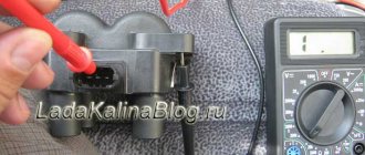
3. Press the lock of the wiring harness block.
While holding the latch in this position, disconnect the wire block from the ignition coil of the first cylinder.
4. Turning on the ignition, use a voltmeter to measure the voltage at terminal 3 of the wiring harness block (the numbering of the terminals is marked on the ignition coil).
5. Similarly, we check the supply voltage to the ignition coils of the second, third and fourth cylinders.
The voltage at the terminal must be at least 12 V. If the voltage does not reach the block or it is less than 12 V, then the battery is discharged, there is a malfunction in the power circuit, or the ECU is faulty.
When the voltage measurement is complete, turn off the ignition.
6. Using an ohmmeter, measure the resistance between the coil terminals. The electrical resistance between pins 1-3 should be close to zero (about 1 ohm). The resistance between pins 1-2 and 2-3 should be high (tend to infinity).
The faulty coil must be replaced.
10 mm socket wrench
Unscrew the bolt securing the ignition coil to the cylinder head cover.
8. Remove the ignition coil from the spark plug well.
Install the ignition coil in reverse order.
I think that there is no need to talk about the fact that VAZ 2110, 2111 and 2112 engines come in both 8 and 16 valves. In previous articles we have already looked at the process of replacing a module with an 8-cell one. motor. Today we’ll look at the example of another power unit - 16V.
On the one hand, this is convenient, and if one of them fails, you won’t have to change everything. On the other hand, maintenance is more expensive when replacing all these parts at once.
It’s quite easy to do the replacement yourself and for this you will need:
- socket head 10
- extension
- ratchet handle
How to check the ignition module of a VAZ 2114
The easiest and most reliable way to find out whether the cause of problems lies in the module is to install a known-good device of a suitable model.
Video tutorial on how to remove the ignition coil of a VAZ 2114
If everything works after replacement, we can say with confidence that the culprit for the unstable operation of the power unit is the ignition module. Since its repair, according to the instruction manual, is not provided for, you will have to go to the store to purchase it.
If it is not possible to borrow a working module from someone, you will need to pick up a multitester, a test light and be patient:
First, measure the resistance between the paired terminals of the secondary winding. To do this, switch the tester to ohmmeter mode. Install the probes on the leads to the first and fourth cylinders, then to the second and third
Here it doesn’t really matter what numbers the display shows (usually about 5.4-5.5 kOhm) - it is important that in both cases the results are identical. If the error is more than 100 Ohms, you are dealing with a secondary fault, which means the module must be replaced
The ignition module is checked using a multitester
- The next test option should be to “ring” the wire block to which the module is connected. Disconnect it and switch the tester to voltmeter mode. Place one probe on contact A, the second on engine ground. Ask your assistant to start the engine (or at least crank the starter) and look at the display readings. The voltage should be around normal 12 volts. Do the same with the second contact.
- If there is no voltage at all, you need to check the fuse. In this case, look at the three fuses on the ECU. This unit is located under the dashboard, on the front passenger side. The fasteners are unscrewed with a Phillips screwdriver. The fuse for the ignition module is third from the top (lowest) and has a rating of 7.5 A. Along with a blown fuse, the reason for the lack of electric current can be broken contacts, corrosion, or broken wires.
https://youtube.com/watch?v=5XM5mrCNE3M
There is another way to check the correct closure of the circuit, which will be very useful if you do not have a multitester at hand. Take a 12 V test light and connect one of its wires to terminal block A, and connect the other to the engine housing. Have a helper turn the ignition key and turn the starter a little. At this moment the light should flicker. Do the same with pin B.
Instructions for replacing the module
If checking the VAZ 2112 ignition module showed that the device needs to be replaced, then you can change the ignition module yourself.
The replacement process looks like this:
- Initially, you should turn off the power to the on-board network; to do this, you just need to disconnect the negative terminal from the battery. Many car enthusiasts neglect this step, although in fact it is very important. If you do not disconnect the battery, a short circuit may occur as a result of moisture or other external influences during repairs. And if this happens, then there is a chance that you will have to completely change the wiring in the car. So, to reset the battery terminal, you just need to unscrew the bolt that secures it with a wrench.
- Having done this, you will need to disconnect all high-voltage wires connected to it from the module. At the same time, you need to remember their location so that during installation you do not accidentally confuse them, which, again, can be fraught with danger for the entire system as a whole.
- After completing these steps, you will need to disconnect the connector with wires from the device itself. To do this, grab the block with your hand and press the latch with which it is attached - the fastener is located at the bottom, you can feel it with your hand. Having done this, you will need to remove the block and put it aside so that it does not interfere with you in the future.
- So, now you have two options - remove the device together with the mount or remove it separately. The first option is usually relevant in cases where, in addition to replacing the MZ, you need to perform other repair actions, for example, to get to the antifreeze drain hole of their cylinder block. Of course, it will be more convenient to dismantle the module separately, but then access to other parts and elements will be blocked. To dismantle you will need to unscrew the nuts with your own hands that secure the device to the bracket. Depending on the car, the nuts can be different; for example, they can be made in the form of hexagonal studs. If so, you will need a hex wrench to unscrew them. In any case, after unscrewing the nuts, it is necessary to dismantle the module from the seat.
- The procedure for installing a new module is carried out in a similar way, only in reverse order. When connecting with your own hands, be careful and be sure to correctly connect all the wires that connect to the module from the spark plugs . If at this stage you mix up the cylinder numbers on the high-voltage cables, the power unit may not work correctly or may not start at all.
Photo gallery “Replacing the MZ with your own hands”
Price issue
The cost of the device directly depends on the manufacturer. For example, the price for a new MZ from the manufacturer SOATE is about 1,700 rubles. A module from the manufacturer BOSCH will cost around 2 thousand rubles, and from General Motors - about 5 thousand rubles.
Ignition VAZ 2110 injector, diagram, spark plugs, ignition module VAZ-2110
Signs of a malfunction in the VAZ 2114 ignition module
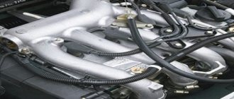
The ignition of the VAZ 2110 injector is fundamentally different from the carburetor versions. Firstly, in the ignition system of the injection “ten” there is no distributor on the camshaft shaft and the main ignition coil, which are typical for all carburetor cars. In the injection models VAZ 2110, 2111, 2112, the ignition system is built without the use of moving elements. A feature of the VAZ 2110 injector ignition is the absence of advance angle adjustments; in addition, the injection ignition of the “tens” does not require any maintenance. The main element of the entire circuit is the ignition module, see the photo of the module at the beginning of our article. The module consists of a pair of ignition coils and electronics that control the distribution of high energy to the spark plugs. In turn, the controller sends commands to the VAZ 2110 injector ignition module. The entire ignition circuit is shown below in our image.
The ignition diagram of the VAZ-2110 injection engine shows the following elements -
- 1 – battery
- 2 – ignition switch
- 3 – ignition relay
- 4 – spark plugs
- 5 – ignition module
- 6 – controller
- 7 – crankshaft position sensor
- 8 – master disk
- A – matching device
The injector spark plugs on the “ten” for an 8-valve engine and for a 16-valve engine are different in design. For 8-valve injectors, spark plugs of the A17DVRM brand are used, for 16-valve power units these are spark plugs AU17DVRM. The latter have a more compact size and are unscrewed with a 16-valve wrench. In the 8-valve cylinder head, the spark plugs are installed in the same way as on the carburetor versions of the engine, but in the 16-valve cylinder head, the spark plugs are recessed vertically into the wells of the cylinder head. The normal gap between the electrodes of these spark plugs is 1.0-1.15 mm.
Sparking in the 2110 injection engine occurs in two cylinders at once. In this case, in one cylinder the spark ignites the working mixture on the compression stroke, and on the second cylinder the spark appears on the exhaust stroke and does not in any way affect the operation of the engine, that is, this is the so-called “idle spark”. Thus, sparking occurs in pairs, which facilitates the entire operation of the power unit. For this purpose, the ignition module contains two high-voltage coils with a constant current direction. The spark appears alternately in cylinders 1-4 and 2-3.
Another important element of the VAZ-2110 ignition is the controller. It is the ignition controller that gives the command to the module that it is time to direct current to certain spark plugs. The controller receives information from the crankshaft position sensors, mass air flow sensor, crankshaft speed and the presence of detonation. Even information about the coolant temperature is used. After processing all the information from the sensors and calculating the sequence of operation of the coils in the module, the controller sends a signal to the module, and from it current flows to the spark plugs. Thanks to this ignition system, the VAZ-2110 injection engine operates stably and reliably.
Methods for diagnosing device performance
No spark. UAZ no spark from ignition coil
The simplest method that will help determine the performance of the coil is to replace it with a similar working device. This is possible if there is somewhere to get it. Please note that the module must match the parameters of the device under test. If the engine with a working coil works as before the breakdown, the ignition module is definitely faulty.
The main testing method involves using a multimeter. It consists in determining the resistance of the secondary windings of the coils built into the ignition module. The method is simple and does not require additional skills. The device does not need to be removed for testing. The check is done with the engine turned off.
This is how you check the resistance of the secondary winding with a multimeter
- High-voltage wires are removed from the module sockets.
- The tester switch is set to the 20 kOhm position.
- The multimeter rods are placed in turn in the recesses of the corresponding contact pairs (1 and 4, 2 and 3).
- With an intact secondary winding, the performance in both cases is the same. Normally, the resistance should be about 5.4 kOhm (in some models the indicators differ, which needs to be clarified). If the resistance is much greater, then there is a winding break. The resistance is much lower - a breakdown. The coil is faulty and cannot be repaired.
Checking the Ministry of Health with your own hands
There are several options for checking the device yourself at home; let’s look at the simplest one. To carry out independent diagnostics, you need to know what the wires connected to the module are responsible for: red-blue - provides 12-volt power to the device; the brown wire is ground, usually connected to the car body; white-blue - connects to the spark plugs of the first and fourth cylinders; the red-gray wire connects to the spark plugs of the second and third cylinders. Diagram of the VAZ module First, you need to check with your own hands that all impulses are supplied to the ignition device 2112: First of all, you need to turn off the ignition and disconnect the connector. Next, the key in the lock must be moved to position I. Now you will need a dial voltmeter; it must be connected to the negative terminal of the battery. With the second probe, that is, the plus one, you need to find the 12-volt contact on the connector. When connected to the control contact, the arrow on the tester will show almost 0. If the starter unit starts working, the parameters may increase, but they will not exceed 0.7 volts. Please note that the voltage level at both control contacts must be identical. There is another test option - you can diagnose the functionality of the module using a pointer ohmmeter. In this case, we mean a pointer tester, not a digital one. First you need to connect the probes of the device to pins 1 and 4 of the module, and after that to pins 2 and 3. Ultimately, the diagnostics should show the same result. Please note that depending on the manufacturer, these parameters may differ: for devices manufactured by ATE-2 with number 3705010-02, this parameter should be about 5-6 kOhm; for SOATE modules with number 3705010-12, diagnostics should show 12 kOhm. If the obtained indicators differ from those described above, then the module must be replaced. Please note that the inductance of the coils installed inside the MZ is quite high, therefore, connecting an ohmmeter, a spark may slip. Therefore, when diagnosing, we strongly do not recommend touching the probe leads at the same time (the author of the video is Avtoelektika HF).
Typical module failures
If you have at least a little knowledge of electronics, as well as a multimeter, you can independently diagnose and identify the problem. Checking the VAZ-2110 ignition module will take a little time, but will save you from purchasing an expensive unit
Please note that sometimes races appear that disappear over time
Errors will remain in the microcontroller, so they can be read using special testers. But as practice shows, at a time when the faults do not manifest themselves, the tester cannot recognize error codes that were previously present but then disappeared. Very often, the cause of failures is dirt on the contacts, poor fastening of the case, lack of mass, and the presence of electrical interference.
Major ignition
.
Removing the ignition module
To repair the ignition module
VAZ-2110, it needs to be dismantled. First, check if there is high voltage on all terminals. The most common breakdown is the lack of spark in the second and third cylinders. If you lightly press down on the rear of the housing, the engine can begin to operate normally. But it won't last long. To withdraw you need:
1. Disconnect ground from the battery.
2. Remove the decorative cover covering the block head, if any.
3. Remove all high-voltage wires.
4. Disconnect all wires going to the ignition module. The white rings indicate the numbering of all wires. On the body of the device there is a designation of cylinder numbers.
5. Disconnect the connector from the device.
6. Unscrew the three nuts securing the block.
That's all, the VAZ-2110 ignition module has been removed, and you can start repairing it.
Module check
After signs similar to failure of the ignition module appear, it must be checked before buying a new one, since its cost is not cheap.
There are three ways to check: substitution, visual inspection and a multimeter.
Substitution
The best and easiest way to check the MZ is to install another known good one from another exactly the same car. After which it will immediately become clear what the matter is and whether the Ministry of Health is to blame for this problem.
Visual inspection
It is necessary to inspect the module for chips, cracks, etc. There should be no damage to it. There should be no moisture or rust on the contact part.
Multimeter
Testing with a multimeter is carried out using the results of voltage and resistance measurements. This will help identify the cause of the failure of the module or its control circuit.
Step by step check
- Remove the power supply from the module. On the multimeter we set the DC voltage measurement limit to 20V. We turn on the ignition on the car and connect the multimeter contact on one side to the power block (namely to connector 15), and on the other side to the engine housing. The voltage between pin 15 and the motor housing must be at least 11-12V. Otherwise, the power supply circuit of the MH is faulty, or the battery is discharged.
- Next, we check the resistance on the VAZ 2110 ignition module itself. We set the multimeter to the resistance measurement parameter, namely 200 Ohms. We connect the multimeter probes to the high-voltage terminals of the MZ: 1-4, 2-3. The resistance of these coils, with a working MC, should be within 5 ohms.
- Then the resistance at the MC input is checked. One multimeter probe is connected to the central contact and the resistance is measured first on the leftmost contact and then on the rightmost one. The resistance should be in the 5 ohm range.
How to restore
Opening the aluminum plate, you will find a small printed circuit board on which the active components are located. It is coated with transparent silicone. It will need to be removed as it will interfere with repairs.
Pay attention to the wires that connect the board and connector pins. They are aluminum, and this metal undergoes destruction much faster than copper
All these wires will need to be replaced. Some motorists who repair modules use wires that are used in mice for personal computers. But you need to get used to working with them - they are covered with paint.
In general, the diagram of the entire module is simple, it contains:
1. Two BU931 transistors (you can use the domestic analogue of KT848A, it performs well and is much cheaper).
2. Two SGS-THOMSON switches (model L497D1).
What you need to know when working with the module
Before working with the module, you must purchase aluminum flux
When replacing transistors, please note that it is very difficult to solder wires to the collector terminals, since they are coated with a special material. And it complicates soldering
To make your work easier, carefully open the spray. Try not to overheat the element. Place it on an aluminum plate so that all the heat goes into it. Otherwise, the semiconductor junction will be destroyed and you will ruin an expensive element.
When soldering wires, make sure that their length is as short as possible. All soldering areas must be coated with varnish, even for nails.
After repairs, be sure to check the functionality of the VAZ-2110 ignition module. If it functions normally, then it is necessary to treat everything inside with auto sealant. This will ensure maximum tightness of the unit - neither water nor dust can get into it. And such a device will last for many years. But if the problem does not lie in the contacts or power transistors, it is better to abandon the idea of repair and purchase a new module - on a VAZ-2110 it costs about 1,500 rubles.
Version of the module on the 8-valve VAZ-2110
Ignition module 2111-3705010 (Stary Oskol).
Ignition module 2112-3705010 for a one and a half liter engine.
The top ten was equipped with two 8-valve engines of different sizes - 1.5 (2111) and 1.6 liters (21114). The ignition modules for these engines are different.
- The one and a half liter engine has a module with article number 2112-3705010,
- and the 1600 cc engine is equipped with module 2111-3705010.
A module for a 1.5 liter engine costs about 1500-2100, and the second one is 500 rubles cheaper.
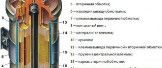
Module structure
The module consists of two ignition coils and two high-voltage switch switches.
Inside the module there is a board with radio components and ignition coils filled with compound.
The coil generates a high voltage pulse, and it is a simple transformer with two windings, primary (induction voltage about 500 V) and secondary (induction voltage at least 20 kV). All this is assembled in a single housing, on which there is a connector for signal wires (from the engine control unit) and four terminals for high-voltage wires.
>
Schematic diagram of the module.
The module operates on the principle of an idle spark - it distributes sparks in pairs to cylinders 1-4 and 2-3 according to impulses transmitted from the ECU.
Checking the ignition module of the injection VAZ 2110 8/16 valves
The top ten may have an eight-valve engine 2111, with a volume of one and a half liters, or an engine 21114, with a volume of 1.6 liters. The difference between them is in the ignition modules.
The module for a one and a half liter engine has the article number 2112-3705010, and the module with a volume of one thousand six hundred cubic meters has the article number 2111-3705010. They also differ in price. If the cost of the first ranges from one and a half thousand rubles to 2100, then the cost of the second is cheaper by about five hundred rubles.
Which one should you choose? The most reliable ones are produced in the city of Stary Oskol.
Module structure
It consists of two ignition coils and two high-voltage switch switches. The coils are designed to create high-voltage pulses.
In essence, it is a simple transformer that has two windings: a primary winding, with an induction voltage of approximately five hundred Volts, and a secondary winding, with an inductive voltage of at least twenty kiloVolts. Everything is placed in one housing with one connector for signal wires and four for high-voltage.
Schematic diagram of the VAZ 2110 module
The operation of the ignition module is based on the “idle spark principle”. The module is capable of distributing a spark in pairs: to the first and fourth, second and third cylinders when transmitting pulses from the electronic control unit.
Possible faults
You can ring the VAZ-2110 ignition module yourself.
The main task of the module is to supply current to the spark plugs. A high-quality spark is enough to ignite the working mixture. If there is no spark, then problems with the engine are inevitable in the form of a decrease in power, an increase in fuel consumption, dips during acceleration, the speed fluctuates, and the engine refuses to work during startup.
Symptoms and check
If one coil fails, two cylinders stop functioning. This is easy to notice, since the engine becomes heated at idle, starting is difficult, gasoline consumption increases sharply, and dynamics are lost.
We remove the connector from the VAZ 2110 module by slightly moving the latch and pulling the wire.
We check the voltage between pin 15 and the block ground.
Circuit for checking the primary windings
Secondary winding test circuit
Scheme for checking the module for short circuit
You need to make sure the spark plugs are working. They are unscrewed and the spark is checked separately on each of the spark plugs. A high-voltage wire is placed on the spark plug head. The spark plug is placed in such a way that the threaded part of the spark plug and the engine mass are in contact. If, when cranking the engine with the starter, the spark is very weak or absent altogether, then it needs to be replaced. If there is no result, you need to check the high-voltage wires. This excludes spark plugs, caps and high-voltage wires from the list of faults. This means it’s time to move on to checking the ignition module. How to do this?
First of all, the body is carefully inspected, the surface of which must be intact. If chips, cracks or burns are detected, then the module must definitely be replaced.
If spark instability is noticed only on the first and fourth, or second and third cylinders, then the conclusion arises that some coil is damaged.
Even if this is the case, due diligence needs to be done.
Checking the VAZ-2110 ignition module with a multimeter 8 valves is as follows:
- The connector with signal wires is disconnected from the module.
- It is then removed from the module. The latch must be moved to the side and pulled by the wire.
- The ignition is turned on to check the voltage at the terminal of the central block of control wires. If there is no voltage when the battery is charged, or if the value is less than the nominal value, which is twelve volts, it is concluded that the electronic control unit is faulty.
- The high-voltage wires are removed, and it is necessary to unscrew and remove the module mounting bots.
- The resistance on the primary windings of the coils is checked. The multimeter is set to resistance measurement mode. Using the device, readings are taken from the rightmost and central terminals, then the leftmost and central ones are checked. The nominal resistance should be about 0.5 ohms.
- The primary windings are checked. The resistance in the secondary windings is measured between the terminals of the first and fourth, second and third high-voltage wires. Nominal resistance 5.4 kiloohms. If a discrepancy is found, it means that the coil is not operating correctly.
- The module is checked for a short circuit. One of the tester probes is installed on the central terminal, the other on the metal body. If there is no indication of a short circuit, a conclusion is drawn that the housing of one of the coils is short-circuited.
Design and principle of operation of the ignition module
Some old-school motorists call the modules double-spark coils, which makes sense. After all, the coil is the predecessor of the ignition module in the technical evolutionary chain. The module is a paired design consisting of two pairs of windings (primary and secondary) and a switch that alternately switches low-voltage current from one coil to another. In some models of double-spark coils, the commutator is structurally located outside the block.
The operation of the module is controlled from an electronic unit that collects and analyzes information from various working components of the engine. The block, unlike the classic coil, has 4 sockets for connecting high voltage wires going to the spark plugs. The pulse occurs in pairs, first at terminals 1 and 4, then 2 and 3. That is, each of the built-in coils is responsible for the operation of two cylinders. A spark occurs simultaneously, as a pair.
This is what one of the ignition module models looks like. The connector for connecting incoming wires is visible at the top.
At the input, the ignition module has a connector with four terminals. Usually most models have markings opposite them. Pulses from the Hall sensor alternately arrive at contacts A and B, serving as a signal to switch the commutator from one primary winding to another. C and D – ground and power supply (12 V), respectively.
Comments and reviews
Ivan Ivanovich Baranov Experience at a service station: View all answers Avtozam.com - your assistant in car repair and maintenance Your use of this website means you agree that you use it at your own risk. Materials: https://avtozam.com/vaz/2112/2111-modul-zazhiganiya/
2 ?
Ignition of gasoline in the cylinders of an internal combustion engine occurs using a spark generated by the ignition system. The ignition module is the main element of the system, creating a spark on the spark plugs using high voltage. Each car manufacturer develops and produces its own original module, but the principle of its operation is the same for all devices. During operation, deviation from the specified parameters or breakdown of the ignition module negatively affects engine operation until the power unit fails. VAZ 2110 ignition module The ignition module of a modern car performs the function of generating high voltage to generate a spark on the spark plugs. It consists of two coils with a closed magnetic circuit and a two-channel switch. Sometimes the switch is made as a separate device, but in most cases it is combined with an electronic control unit for the engine. Externally, the modules differ in the number of wires of the connection connector: the module with the switch has 4 wires, and the paired coils have 3. The ignition module is controlled by the ECU, which supplies the windings of its coils with constant voltage at the right time in the form of low-voltage control signals. The end of the signal is the beginning of the spark. Thanks to magnetic induction, at the moment of application, a high voltage is generated, creating a spark at the spark plug. The device is located in the engine compartment and can be easily identified by the high-voltage wires leading to the spark plugs. Checking the ignition module with a removed spark plug. A malfunction of the ignition module is determined by the following symptoms: Difficulty starting a cold engine due to the lack of a spark on one or more spark plugs. Floating engine speed at idle is a situation in which the speed changes without any action on the part of the driver. Dips in power, which manifests itself during acceleration and driving up a long climb. Decrease in engine power. Cylinders 1-4 or 2-3 do not work (engine “troits”). Indication of the “Check Engine” indicator. Despite the high reliability and durability of the ignition module, during operation it can fail, like any other mechanism. Among all the possible causes of breakdowns, in 9 out of 10 cases the following occur and are diagnosed: The use of inappropriate components in the ignition system. High-voltage wires are selected based on the parameters of the module, since excessively high or low voltage creates malfunctions or burns out contacts. Defective or damaged parts, poor quality assembly. Defective components break down faster and damage other components or elements of the system. Practice shows that the selection of high-quality components and their periodic diagnostics allow the module to remain operational for a long time. Checking the ignition module for functionality is carried out in the following ways: Replacing the ignition module with a known good one 1. The easiest way is to connect a known working module. In this case, the devices must be completely identical, the high-voltage wires are in good condition, and the reliability of the contacts has been checked. Checking contacts on the ignition module 2. Movement of the module, which allows you to identify unreliable contacts. To do this, move the wire block and the module itself. If during exposure the engine reacts by changing its operation, then the cause of the problem lies in poor contact. Resistance measurement at the terminals of the ignition module 3. Resistance measurement. To do this, you will need a tester switched to ohmmeter mode. Measurements are carried out on the paired terminals of the module between cylinders 1 and 4, as well as cylinders 2 and 3. The resistance value should be the same and approach 5.4 kOhm. Checking the ignition module using a tester 4. Checking the voltage with a tester. One probe of the device is applied to contact A of the block, the second to ground. After turning on the ignition, take readings from the device. If the wire is in good condition, it will show a voltage of 12 V; if it is missing, check the fuse protecting the ignition module. Then check the continuity of the circuit with a 12 V test lamp. Apply one end of the wire to contact A and rotate the starter. If the lamp does not blink, the circuit is broken. The procedure is repeated in a similar way with other contacts. Diagnostics of the ignition module with professional equipment 5. Diagnostics at a service station by connecting a computer with special software to the ECU. Malfunctions are detected in the form of errors indicated by an alphanumeric code, after which a more in-depth diagnosis of the malfunction is carried out to make a decision - repair the ignition module or replace it. A similar check is carried out at a specialized service station using an oscilloscope. VAZ 2107 ignition module The design of the ignition module is quite complex: it includes one or more coils, a board, contacts and wires. Of all the above elements, only contact connections can be repaired; in some cases, replacement of parts (transistors, coils) is possible. The module is dismantled and opened for repair purposes. To do this you will need: Socket wrenches with heads 1, 13 and 17. Hexagon 5. Screwdriver. Soldering iron. Flux for aluminum. Stranded wire. Nail polish. Opening the ignition module Repair of the ignition module is carried out in the following order: On the removed device, open the housing by prying it off with a screwdriver. Remove the silicone film covering the board. All aluminum is removed from the explosive contacts. On the board, new wires are soldered in place of all the dismantled old ones. To do this, the surface of the collector is cleaned of deposits, after which the board is heated to 180 o C (a characteristic smell will indicate when the desired temperature has been reached). During the soldering process, the ends of the wires are connected to the module. At the end of the operation, all contacts, the board and the module are covered with nail polish. The device is assembled in the reverse order, installed on the car and the engine is started. In case of normal operation, the ignition module is sealed tightly with sealant, while the wires are tucked inside the cavity so that they are not pinched at the edges by the plate. If the device does not work, then a breakdown inside the module should be looked for more carefully. The transistor, electronic component may have failed, or there may be a break in the coil. Such a repair makes sense only if its price is significantly lower than the cost of a new part.
Knock sensor
Engine oil pump
No comments yet
Leave a comment Cancel
You must be logged in to post a comment. Materials: https://voditelauto.ru/kak-proverit-modul-zagiganiya/
3 ?
Some gasoline engines that are installed on modern domestic and imported cars are equipped with ignition modules, which are a pulsed high-voltage current source. There are situations when these devices fail, leading to a complete or partial loss of performance of the car engine. Ways to check for a malfunction in the ignition module in a garage are covered in this article. Some old-school motorists call the modules double-spark coils, which makes sense. After all, the coil is the predecessor of the ignition module in the technical evolutionary chain. The module is a paired design consisting of two pairs of windings (primary and secondary) and a switch that alternately switches low-voltage current from one coil to another. In some models of double-spark coils, the commutator is structurally located outside the block. The operation of the module is controlled from an electronic unit that collects and analyzes information from various working components of the engine. The block, unlike the classic coil, has 4 sockets for connecting high voltage wires going to the spark plugs. The pulse occurs in pairs, first at terminals 1 and 4, then 2 and 3. That is, each of the built-in coils is responsible for the operation of two cylinders. A spark occurs simultaneously, as a pair. This is what one of the ignition module models looks like. The connector for connecting incoming wires is visible at the top. At the input, the ignition module has a connector with four terminals. Usually most models have markings opposite them. Pulses from the Hall sensor alternately arrive at contacts A and B, serving as a signal to switch the commutator from one primary winding to another. C and D – ground and power supply (12 V), respectively. The weak point of the ignition coils and modules is the secondary winding, which generates a high voltage pulse. A coil break or breakdown may occur in it. The following factors lead to this phenomenon: the use of low-quality or unsuitable candles; operation with non-functioning high voltage wires; frequent attempts to check the spark. The high-voltage pulse arising in the secondary winding must be realized (spent). If this does not happen (if the integrity of a high voltage wire is broken, for example), a high-energy electrical pulse seeks an outlet. He will find it, with a high degree of probability, in the thin secondary winding. Often, a module malfunction occurs when the integrity of poor-quality factory soldering of wires going to the switch elements is violated. This happens from vibration. Also, the cause of non-working coils can be a banal contact failure in the incoming connector. Another factor leading to a malfunction of the ignition unit is often moisture that gets on the device during washing or driving in unusual conditions. It is extremely rare for two built-in coils to fail at once, so it is more likely to be possible to start the engine with a faulty unit. However, even an inexperienced driver will immediately suspect something is wrong. The malfunction will manifest itself as follows: unstable (floating) idle speed; the engine has difficulty picking up speed; characteristic sound of the engine (triple); jerking when accelerating (while moving). Operating a car with such a breakdown is possible (you can drive to a garage or car service station), but it is not advisable unless absolutely necessary. Similar signs of unstable engine operation are possible with a number of other ignition or fuel supply faults. To differentiate possible breakdowns, the performance of the ignition unit should be determined. It would be useful to check the contacts of the wires coming to the device, as well as their integrity. Before testing the performance of the coils, you should make sure that a possible breakdown is not caused by a loss of power to the device. First, you need to try to simply restore contact by moving it several times or disconnecting/connecting the block of wires included in the connector. If such manipulation does not lead to improved engine performance, a tester (multimeter) is used to determine the quality of incoming pulses. The block of wires is removed from the connector. On the block, each terminal (A, B, C, D) has a corresponding socket. Testing with the engine running is done as follows. The first contact of the tester is in socket D, the second is to ground. The multimeter switch position is 20 volts. If there is power, the tester shows 12 volts. The first contact is in socket C, the second is ground. Switch on ohmmeter (20 Ohm). Normally it shows less than 1 ohm, that is, the mass is normal. The first contact is in socket B, the second is ground. 20 volt switch. The norm is not less than 0.3 volts. If this is the case, it means that a normal pulse is coming from the Hall sensor to position B. Contact A is checked in the same way as the previous one. If such a check shows the norm, you need to test the module. If not, look for the cause in the electrical circuit to the coil. The simplest method that will help determine the performance of the coil is to replace it with a similar working device. This is possible if there is somewhere to get it. Please note that the module must match the parameters of the device under test. If the engine with a working coil works as before the breakdown, the ignition module is definitely faulty. The main testing method involves using a multimeter. It consists in determining the resistance of the secondary windings of the coils built into the ignition module. The method is simple and does not require additional skills. The device does not need to be removed for testing. The check is done with the engine turned off. This is how the resistance of the secondary winding is checked with a multimeter. High-voltage wires are removed from the module sockets. The tester switch is set to the 20 kOhm position. The multimeter rods are placed in turn in the recesses of the corresponding contact pairs (1 and 4, 2 and 3). With an intact secondary winding, the performance in both cases is the same. Normally, the resistance should be about 5.4 kOhm (in some models the indicators differ, which needs to be clarified). If the resistance is much greater, then there is a winding break. The resistance is much lower - a breakdown. The coil is faulty and cannot be repaired.
Video: How to check the secondary winding with a multimeter
If during testing both secondary windings show integrity and serviceability, the reason for the inoperability of the coils may be a break in the soldering of the switch wires. Such damage is detected when the rear cover of the module is removed. If you have a soldering iron and know how to use it, you can restore the integrity of damaged contacts, while at the same time strengthening the rest. This, unfortunately, is the only failure of the ignition module that can be repaired. Testing the ignition module can be done using simple do-it-yourself instruments. Based on our advice, you will be able to fully check both the module itself and other elements of the mechanism that may be the cause of the breakdown. We wish you success in this matter! Materials: https://motorltd.ru/sposobyi-samostoyatelnoy-proverki-modulya-zazhiganiya/
Repair of ignition module 2112 -3705010-02 for cars of the VAZ-2110 family
Automotive equipment
Home Electronics repair Automotive equipment
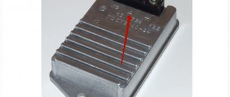
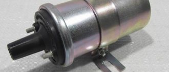
When operating a VAZ-21102 car, after 15,000 km, an unusual malfunction appeared: from time to time the high voltage on cylinders 2 and 3 disappeared. All suspicions immediately fell on the ignition module (Fig. 1).
Rice. 1. Appearance of the ignition module 2112-3705010-02
When examining the module with the engine running, it was noticed that if you press on the aluminum plate on the back of the module, the engine starts to work normally. It would seem that everything is clear, and you need to purchase a new ignition module, but the price is too high. It was decided to open the faulty module and study the material part of the “miracle” of our automobile industry. Using a flat screwdriver, bend the aluminum plate (Fig. 2).
Rice. 2. Opening the ignition module
Rice. 3. Appearance of the opened ignition module
What do we see there? A small printed circuit board with elements (Fig. 3). It is covered with a thick layer of transparent silicone, which must be carefully removed to access the elements. The connecting wires between the board and the module pads are made of aluminum. “So this is where my destruction was hidden…” - these wires are quite flimsy and, it seems, one of them could not withstand the shaking of Russian highways and broke.
But this is no longer important, because when opening it, we tear off all the wires from all the contacts and replace them with new ones (preferably the MGTF brand). Let's take a closer look at the active elements of the module
Let's take a closer look at the active elements of the module.
Rice. 4. Appearance of the ignition module printed circuit board
As can be seen from Fig. 4, the circuit consists of two L497D1 type switches and two BU931 type power transistors.
Let's start restoring connections. When soldering, it turned out that the contacts on the module are made of aluminum and cannot be soldered with regular flux, so you will have to purchase a special flux for aluminum.
Rice. 5. Assignment of ignition module contacts
When restoring a module, it is advisable to follow the following technology:
1. First, solder the wires to the board. Moreover, it is necessary to remove the remnants of old wires from the board.
Particular difficulty was caused by soldering the wires to the collectors of the transistors. They are coated with metal that is difficult to solder. The burr machine helped remove the deposit of this metal down to the copper base, but that’s not all. When touched with a soldering iron, its heat was instantly dissipated on the aluminum radiator plate. In order to solder normally, I had to put the entire plate on an electric stove and heat it to about 180 degrees. To do without a stove, you can use a soldering iron with a power of 80...100 W.
2. Solder the board wires to the corresponding contacts inside the module, trying to make them as short as possible.
3
We cover the soldering areas with some kind of varnish (if there is no technical varnish, nail polish will do, it is only important that the spouse does not notice this)
Rice. 6. Appearance of the repaired module
The result should be a structure like in Fig. 6.
Before final assembly, it is advisable to conduct general tests of the device to ensure its performance. If the device is working, then after coating the inner surface with automotive sealant, we carry out the final assembly, tucking the wires into the cavity so that they are not pinched by the plate at the edges. Well, if the device does not work, then you will have to look for the fault more carefully. Perhaps this is a failure of electronic components (especially output transistors), an open circuit or a short circuit in the coils. In conclusion, for the “folk crazy people”, I would like to say about the price of spare parts. The L497D1 switch costs about $3, and the BU931 transistor costs about $6.
You can try to replace the transistors with cheap domestic ones like KT848A, but their sizes are impressive and, in case of replacement, you will have to rack your brains over installing them inside the module housing.
- Sergey / 04/27/2012 - 15:57 and how to check it. only by car.
- Sergey / 04/27/2012 - 15:55 nothing. useful information.
- master / 03/29/2012 - 13:27 thank you
You can leave your comment, opinion or question on the above material:
All about the ignition module on the product of the domestic automotive industry - “Ten”
The engine control system includes many different components necessary for the normal functioning of the unit. One of these in the VAZ 2110 car is the ignition module. In this article we will talk in detail about the design, malfunctions, and repair of this mechanism.
"Ten" in metallic color
The ignition module for a VAZ 2110 with a carburetor or injector engine with 8 or 16 valves includes several elements:
- two ignition coils designed to generate high-voltage signals, subsequently supplied to the spark plugs themselves;
- two-channel switch device.
It is these main components that ensure the normal operation of the ignition module circuit on an 8- or 16-valve engine. The reasons for device failure can be very diverse, ranging from malfunctions of the power unit to the inability to start it in principle. It should be noted that if there is a malfunction in the operation of the module, the Check Engine light on the dashboard will not light up.
Common faults
Checking the ignition module will not cause problems for a driver who understands something about electrical engineering and knows how to use a diagnostic tester - a multimeter. If you do not have experience in performing such tasks, then it is better to contact specialists with such a problem. Signs of device malfunction should be checked using the tester, as this will provide the most accurate test results. Accordingly, with the correct results, the motorist will always know what exactly to pay attention to during repairs.
Module connection diagram
There is no need to rush to repair a module on a 16-valve engine, since often the problem does not lie in this unit. Before you begin diagnosing the device, you must carefully check other, more important components of the vehicle. For example, the ignition control unit. Before diagnosing the device, you must make sure that all other components and systems of the power unit are functioning correctly and without interruption.
As practice shows. Often short-term malfunctions appear in the operation of the unit, which disappear over time on their own. The power unit diagnostic indicator does not record breakdowns of this type, but they remain in the memory of the control unit, and for a long time. If you try to read combinations of errors on the controller using a tester, the results may not yield anything. That is, the tester will not show anything, since there were problems, but now they are gone.
What are the signs of a node failure:
- The speed of the 16-valve engine floats when idling;
- the engine doubles - when it is running, you will hear that only one pair of cylinders is working;
- When accelerating, you can notice how the traction decreases and the power of the power unit drops.
We figured out the signs. As for the main reasons for the failure of this unit, first of all it may be dirty contacts of the unit. In addition, the reason may be poor fastening of the mass, various interferences, etc. (the author of the video about module diagnostics is Evgeniy Popov).
Repair recommendations
As you already understand, the main malfunction of the 16-valve engine is the disappearance of contacts. Therefore, repairing the VAZ 2110 ignition module comes down to restoring them. If the voltage on the cylinders does disappear, the problem can be solved briefly by pressing the rear plate of the module. But you won't do this all the time, will you? Therefore, it is necessary to diagnose the mechanism, replace it, or try to repair it.
Algorithm of actions
First you need to dismantle the mechanism on the 16 valve engine.
This procedure is performed as follows:
- First you need to disconnect the negative cable from the car battery. Having done this, you can remove the plastic cover that covers the power unit.
- Then you need to remove the high-voltage cables from the spark plugs.
- Having done this, you can disconnect the wiring from the module itself. The pinout of the wires is marked on white rings. As for the number of the cylinder for which one or another wire is responsible in accordance with the pinout, it is marked on the body of the mechanism.
- Next, you need to disconnect the connector from the mechanism.
- Using a 10mm wrench, or rather a socket wrench, you need to unscrew the three nuts that secure the block itself. Remove it carefully. After removal, you can proceed directly to the repair. First, you need to open the aluminum plate on the mechanism itself, to do this, use a flat-head screwdriver.
- Having opened the block, you can see a small circuit with electronic elements; it is covered with a layer of silicone. To repair this layer will need to be removed. In addition, here you can see the wires that connect the circuit to the contacts. These wires themselves are aluminum, you will need to tear them off, you should not worry about this, since new ones will be installed instead. According to many experts, in “tens” it is advisable to use multi-core wires, like those used in computer mice.
- The mechanism circuit itself includes two transistors, as well as two switches. Typically, the need to replace these elements is very rare, but if you decide to change them, you will need to use SGS-THOMSON devices. As for transistors, these are devices of the BU931 type.
- Since the contacts themselves are aluminum, you will need flux to work with them. The wire itself is soldered to the circuit using a soldering iron. Please note that it will be more difficult to solder wires to the collectors of the transistor, since they are coated with a special material. Therefore, the top coating must be hidden most carefully. To ensure that the soldering iron does not transfer heat to the plate itself, it must be preheated to approximately 180 degrees. New wires are soldered to the contacts on the mechanism, and their length should be as short as possible.
- In those places where soldering was carried out, the contacts will need to be opened with varnish; for this you can use regular nail polish.
- After all the steps have been completed, you need to check the functionality of the device. If everything works correctly, the inner plane of the mechanism should be treated with automotive sealant, then the assembly will need to be assembled. There is nothing complicated about this; assembly is carried out in the reverse order. After the assembly is completed, you need to make sure that the wires inside the module are not compressed and their integrity is not compromised.
1. Remove the module.
2. Take it apart. 3. Solder the contacts. In general, the mechanism repair procedure is not particularly complicated, but when performing it you need to be as careful as possible. It is also important to follow the sequence of actions; you need to be most careful when soldering contacts. In this article we only looked at repairing ignition contacts, but this problem is not the only one for the module.
In some cases, pinout of the node is required, but this procedure is best left to professionals. If the cause of the unit malfunction is different, then it would be better to replace it with a new one. There are experts who believe that it is better to immediately buy a new module.
Video “Repairing the ignition module”
Visual repair instructions are shown in the video below (video author: Evgeniy Popov).
AvtoZam.com
Typical ignition coil faults
Improper "grounding" can lead to modulator failure. There is also a risk of high voltage electrical shock. The absence of a spark may also indicate a faulty high voltage wire. If a spark appears when replacing it, it means the wire was faulty. How to check the diode bridge of a VAZ generator at home. If not, it's a faulty ignition
.
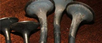
When visually inspecting it, you should also pay attention to possible cracks in the housing. In the vast majority of cases, a faulty ignition module must be replaced
The test, as in the case of a frame coil, includes measuring the resistance of the primary and secondary windings of the coils. The resistance value may depend on the ignition
and its manufacturer. Engine mountings: how to check the vacuum brake booster of a VAZ 2109? How to check. In this case, the resistance of the secondary winding of the coils of the first - fourth and second - third cylinders should be the same, ±100 Ohms.
Customized ignition coils
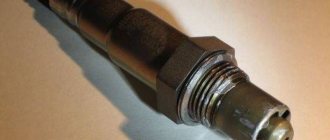
also called compact, plug, pencil or contact because of their appearance, design and location immediately above the insulator of each spark plug.
Photos and names of these ignition
can be found on the Internet. https://100video.info/ how to properly check a quick check of the VAZ 2101-2107 generator. They are used in 16-valve injection engines of the VAZ 2110. At a higher price, their advantages are compactness, practicality, reliability and durability. In addition, the use of individual coils made it possible to eliminate the need for high-voltage wires between the coil and the tip of the spark plug.
The BSZ coil ensures sparking in all cylinders. In the case of using an individual ignition coil, a spark is generated on the electrodes of the spark plug once per engine operating cycle, and only on the spark plug with which the coil works. How to check the ignition coil of a VAZ-2114 8 valves
Speaking about possible malfunctions of the individual ignition coil of the VAZ 2110, you need, first of all, to pay attention to the secondary winding. Violation of its insulation, according to statistics, is most often the cause of high voltage breakdown inside the coil, which leads to its incorrect and unstable operation
Ignition of the mixture in the combustion chamber at low or idle engine speeds can occur with sufficient efficiency, but under load such a coil is not able to provide an impulse to generate a spark. Such a malfunction can be determined, quite imprecisely, at home or using an oscilloscope at a service station. How to wash the injector at home VAZ 2115 video; tip 2: how to remove the gas tank. Checking the VAZ 2110 ignition coil at home is as follows:
- If, under various operating modes of the power unit, deviations from the standard operating mode are observed (the engine is running rough), and there is no doubt about the performance of the spark plugs, perhaps the reason is in the ignition
. In this case, you can swap the coil of the idle cylinder, which can be determined by the state of the spark plug, with any other coil. - the ignition coil
is most likely faulty.
You can install it in place and drive to a service station, but if the “diagnosis” is confirmed by a service station specialist, it will have to be replaced with a new one.
The process of checking all ignition coils on a VAZ-2112
The VAZ-2112 engine with 16 valves uses individual Bosch ignition coils and in order to check them, the following procedure must be followed:
- First of all, we remove each coil from its landing well.
- Then we turn off the power supply and remove them all together as an assembly.
- First of all, we pay attention to its external condition, the absence of cracks and various breaks.
- The same applies to the spring located inside the coil, look at its position, it should be exactly in the center.
Despite the fact that many people on the Internet talk about the impossibility of checking a coil with their own hands, it is possible to check it only by knowing their initial values, which are measured in ohms .
- In order not to make false measurements, first of all we check the internal resistance of the wires and the multimeter itself . To do this, switch the device to the OM position and connect the probes to each other. What value the multimeter gives is its internal resistance. The value can range from 0.0 to 0.3 ohm.
- First of all, we “ring” the primary winding, which is located on the first and third contacts; when connecting, the polarity does not matter.
- Depending on the presence of error readings and coil readings, we add up the final indicators. For example, if the internal resistance is 0.2 ohms and the coil value is 0.7 ohms, therefore the correct value would be 0.5 ohms. Which is the norm.
- We continue diagnostics with each of the coils.
- If it happens that there are no indications, then we once again check the quality of the connections and the correctness of the connection. If the readings are still zero, then the primary winding on this coil is faulty.
When the readings on the primary winding on all coils are correct and show their values, we proceed to checking the secondary winding.
- To do this, set the switch to 2000 kOhm mode.
- Next, we place the multimeter probe on the coil, observing the polarity, black to pin 2, which is located exactly in the middle of the connector, and the red probe to the spring, inside the rubber plug.
- Three-digit values will mean the coil is working properly, and infinity values will indicate its failure.
- Please note that if you cannot measure the resistance correctly the first time, you can wipe the fixed elements from dirt and deposits, since dirty parts can interfere with the signal output.
- When replacing old coils with new ones, you should strictly use analogues, taking the faulty part with you to the store in advance.
Checking module power
Before testing the performance of the coils, you should make sure that a possible breakdown is not caused by a loss of power to the device. First, you need to try to simply restore contact by moving it several times or disconnecting/connecting the block of wires included in the connector. If such manipulation does not lead to improved engine performance, a tester (multimeter) is used to determine the quality of incoming pulses.
The block of wires is removed from the connector. On the block, each terminal (A, B, C, D) has a corresponding socket. Testing with the engine running is done as follows.
- The first contact of the tester is in socket D, the second is to ground. The multimeter switch position is 20 volts. If there is power, the tester shows 12 volts.
- The first contact is in socket C, the second is ground. Switch on ohmmeter (20 Ohm). Normally it shows less than 1 ohm, that is, the mass is normal.
- The first contact is in socket B, the second is ground. 20 volt switch. The norm is not less than 0.3 volts. If this is so, it means that a normal pulse is coming from the Hall sensor to position B.
- Contact A is checked similarly to the previous one.
If such a check shows the norm, you need to test the module. If not, look for the cause in the electrical circuit to the coil.
Malfunctions of ignition modules on the VAZ-2110. DIY diagnostics
The main task of the module is to distribute a high-quality spark sufficient to ignite the working mixture.
If this does not happen, problems begin with the motor:
- power drop;
- high gasoline consumption;
- failures during acceleration;
- unstable idle speed;
- engine failure when starting.
Signs
- If one of the module coils completely fails, then two cylinders do not work. This is clearly visible even to the naked eye - the engine is feverish at idle, starting is difficult, fuel consumption is sky-high, loss of dynamics.
- To eliminate all other components of the ignition system, make sure that the spark plugs are in working order. To do this, unscrew them and check the spark on each of the spark plugs by cranking the engine with the starter and placing the spark plug with the high-voltage wire on the head so that the body (threaded part) of the spark plug touches the engine mass. If there is no spark or it is weak, replace the spark plug with one that is known to work.
- If this does not lead to anything, check the high-voltage wires. Thus, we will exclude spark plugs, caps and high-voltage wires from the list of non-working elements. Next we will check the ignition module.
Filled candles.
Dirty spark plug electrodes.
Breakdown of the spark plug insulator.
How to check the ignition module?
- First of all, we carefully inspect the module body. There should be no chips, burns or cracks on its surface. A module with a damaged casing is replaced without any hassle.
- If the spark is unstable only on cylinders 1-4 or 2-3, one of the module coils is probably damaged. In any case, we will conduct a comprehensive check of the device. For this we will need a regular multimeter.
Multimeter for checking the ignition module.
Diagnostic procedure
The diagnostic procedure can be as follows:
- Disconnect the connector with signal wires from the module.
Remove the connector from the module by moving the lock slightly and pulling the wire. - Turn on the ignition and check the voltage at terminal 15 (central) of the control wire block.
The rated voltage is 12 V. A drop or absence of voltage when the battery is charged indicates that the engine control unit does not supply power to the module. This means the reason lies in the ECU. We check the voltage between pin 15 and the block ground. - We remove the high-voltage wires, unscrew the module mounting bots and remove it. Using a 13mm wrench, unscrew the bolts attaching to the cylinder block. Unscrew the bolts securing the clutch housing. Remove the module along with the bracket.
- We check the resistance of the primary windings of the coils - put the multimeter in resistance measurement mode and take readings from the rightmost and central terminals, then from the leftmost and central terminals.
The nominal resistance of the primary windings is approximately 0.5 Ohm. Scheme for checking the primary windings. - We measure the resistance of the secondary windings between terminals 1-4 and 2-3 high-voltage wires.
Nominal value: 5.4 kOhm. If the readings do not correspond to the nominal value, the coil is not working correctly. Scheme for checking secondary windings. - Check the module for a short circuit.
To do this, install one tester probe on the central pin 15, the second on the metal body. The device should show the absence of a short circuit (one or infinity). Otherwise, one of the coils has shorted to the housing. Scheme for checking the module for short circuit.
Errors
A module malfunction can also be determined using an error scanner. Error codes associated with the module are:
- R-3000, R-3001, R-3002, R-3003 and R-3004 - gaps in sparking, the module itself, spark plugs, high-voltage wires or the ECU may be to blame;
- R-0351 - the coil of cylinders 1-4 does not work;
- R-0352 - the coil of 2-3 cylinders does not work.
The scanner readings do not yet indicate problems with the module itself.
It is possible that the spark plugs are not working or the high-voltage wires are broken, but if we initially diagnosed them, then the fault lies entirely with the ignition module. In this case, we can repair it ourselves, or buy a new one, which is faster, easier and guarantees uninterrupted operation of the ignition system. Good luck to everyone, strong spark and good roads!
>
How can you check the coils?
In any case, checking the ignition coil on a Priora always begins with its external inspection. Even very small cracks or tears in its elastic bands are not allowed. Their presence indicates that the device has been replaced.
Cracks, chips and other damage to plastic parts indicate that the coil was overheated and it could simply “burn out”. Next, the internal parts are inspected, especially the spiral, its location. If the inspection does not reveal any visible defects, proceed to further inspection.
There are several ways to check the ignition coil, which will be discussed below. During the operation of the machine, it is not often, but there is a need to check it. Doing this when there are no obvious signs of failure is not easy without special equipment such as a spark gap or an oscilloscope.
Let's look at how to check the ignition coil without instruments. To begin with, you can simply swap the devices and see how the engine behaves after that. If the interruptions move into the cylinder along with the coil, then there is a malfunction in it and it needs to be replaced.
You can check the high-voltage ignition coil directly on the car. To do this, you need to remove it from the engine, insert a working spark plug into the high-voltage terminal, turn off the fuel pump and, with the ignition on, crank the engine with the starter. A working coil will show itself as a spark on the spark plug. In this case, you must beware of high voltage and use protective equipment.
In cars that have an on-board computer installed, the system will report problems in the cylinders with a signal in the form of numbers from 0301 to 0304, where the last digit indicates the number of the “problem” cylinder. All that remains is to figure out who is to blame, the coil or the spark plug.
After visual inspection and control, you can begin checking using measuring instruments. It is best to use digital multimeters for these purposes, or devices such as MD-1 or AZ-1. They can be freely purchased, and their price is low. Now let's talk about how to check the ignition coil on a Priora using instruments.
Before checking, the device must be removed from the engine. This can be done this way:
- Disconnect the battery terminals;
- Remove the protective plastic casing from the engine;
- Squeeze the latch with your fingers and disconnect the connector with wires;
- Using a “10” wrench, unscrew the fastening bolt and remove the coil from the mounting socket.
We unscrew the coil with a key - it’s simple! (naturally, the internal combustion engine has 16 valves, a coil of spark plugs in the well) Now you can start checking with instruments. First you need to check and calibrate the measuring device. To do this, set the measurement switch to the position for measuring resistance at “200 Ohms”, and connect the probes to each other.
- Both probes of the device are connected to the coil connector (polarity is not necessary) and the resistance of the primary (low-voltage) winding is measured. Pinout of contacts for measurements 1 and 3, measuring limit of the device is “200 Ohm”. It should show approximately 0.8 ohms. The indicator obtained during calibration is subtracted from this value and the true value of the winding resistance is obtained. If there are no readings, you need to check the reliability of the contact between the probes and the coil leads. If after several attempts the readings do not appear, it means that there is a break in the primary winding and it must be replaced;
- The next step will be to check the high voltage winding. Set the resistance measurement limit to 2 MΩ. In this case, polarity must be observed, since the high-voltage winding has a diode. Therefore, the red probe is inserted into the coil terminal, and the black one is connected to the connector terminal number 2, which is the middle one in the block. The device should show approximately 342 kOhm. It should be taken into account that the readings of the device are highly dependent on the heating of the coil. It is best to test on a cold coil. In this case, it is also necessary to ensure good contact of the device probe with the high-voltage terminal. If the readings are close to infinity, the part needs to be replaced.
Checking with a multimeter A little about whether the ignition coil can be repaired. It is not possible to restore the primary or secondary winding, but even novice drivers can replace the tip on it. To do this, stock up:
- New tip:
- New sealing ring;
- Degreasing agent;
- High temperature silicone sealant.
The site where the tip is installed is cleaned and thoroughly degreased. The skirt of the new tip must be turned inside out and a small layer of sealant applied to it. While it dries a little, install a new O-ring.
Next you need to install the rubber tip in its place. This will complete the repairs.
Signs of malfunction of the ignition module of VAZ 2110 and 2114. We disassemble and fix
- P3000 (and also 3001-3004) – the ignition in the cylinders does not work;
- P0351 – winding break in a pair of 1/4 cylinders;
- P0352 – winding breakage in a pair of 2/3 cylinders.
- Remove the negative from the battery (disconnect the terminal);
- Remove the tips from the spark plugs;
- We press out the fastening clamp. Disconnect the wire block from the ignition coil;
- We unscrew the fastenings of the gearbox bracket, as well as the lower bolt on the cylinder block fastening;
- We take out the ignition coil together with the bracket, disconnect the wires;
- We release the fastening of the bracket and coil;
- We remove the coil and replace it with a known-good similar device. Reassemble in reverse order;
- If everything works, then the problem is in the ignition coil. As a rule, it is not repaired, but simply replaced with a new device. So you’ll have to run to the nearest auto store or car market to get the required spare part.
AutoFlit.ru
conclusions
Thanks to this simple procedure, you can quickly check the performance of the ignition coils on a VAZ-2112 with your own hands, without resorting to the help of special diagnostic stations and specialists.
You will need a 5mm hex key.
If the ignition coil is removed to gain access to the coolant drain hole from the cylinder block, then it is necessary to remove the coil along with the bracket (see “Replacing the ignition module on engines 2111 and 2112”)