The injection pump or high pressure fuel pump is one of the most complex and specific elements of modern diesel engines. In addition to this type of engine, such units are used in injection power units, which supply gasoline directly to the cylinders.
The significant cost of the pump is determined by the complexity of its manufacture, associated with the need to use high-precision production equipment. The functioning of the entire power unit depends on the quality and stability of the high-pressure fuel pump, since it is responsible not only for pumping fuel, but also for dispensing portions of the mixture and supplying them to the nozzles at a given time.
What does it represent?
The injection pump is one of the main components of the fuel supply system of diesel engines and is designed to timely supply a portion of the mixture into the combustion chamber. A feature of this fuel is the dependence of the quality of ignition on the level of pressure applied. The action of the standard piston system in this case is not enough, since it is necessary to increase the pressure to 150 MPa or more. To ensure this condition, a specific injection pump is used for diesel power units.
With the advent of the industrial version of Common Rail type systems, in which the nozzles are controlled electronically, the functionality of the pump was limited to one action - monitoring the level of discharge pressure.
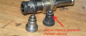
Operating principle of the fuel pressure regulator
The principle of operation of the regulator is as follows: when the engine is stopped (when the pump is not pumping fuel), a spring through a membrane presses the valve to the seat on the drain channel, and it is in the closed position. After starting the engine, the fuel pump pumps gasoline into the ramp, from where it enters the fuel chamber of the RTD. While the pressure is insignificant, due to the stiffness of the spring, the valve remains closed, which will ensure an increase in pressure.
As the pressure increases, the fuel acts on the membrane, and as soon as it exceeds the spring stiffness, the membrane shifts towards the vacuum chamber, which pulls the valve along with it. As a result, the “return” channel opens slightly and part of the gasoline goes into the drain - the pressure is released to a level at which the spring again closes the drain channel with a valve. But as already noted, the fuel pressure regulator “adapts” to the operation of the engine. And for this, the vacuum created in the intake manifold is used.
The vacuum chamber of the RTD is connected to the manifold, so the resulting vacuum is transferred to the specified chamber. Let's consider the effect of vacuum on the functioning of the regulator using two examples:
- The engine is idling. In this mode, a large supply of gasoline in the ramp is not required, since the consumption at idle is minimal, which means that increased pressure is not needed. At XX, the throttle valve is closed and no air is supplied through it. As a result, a lack of air—a vacuum—forms in the collector. This vacuum, acting on the regulator membrane, creates additional resistance to the stiffness of the spring - its force is reduced and less fuel pressure is needed to open the valve; excess fuel is discharged at the lower limit of the operating pressure range.
- The motor is operating under maximum load. Fuel consumption in this mode is high and requires increased pressure in the rail, in fact, a reserve of it, so that it is enough for normal operation of the engine. Under this operating condition, the throttle valve is open and air flows freely into the intake manifold, which is why there is no vacuum. And since there is no vacuum, there is no additional resistance to the spring. Only fuel pressure is used to compress it. As a result, the reset occurs at the upper limit of the range, which ensures the necessary supply of gasoline in the ramp.
By using only the spring stiffness and vacuum in the manifold, the regulator quickly responds to changes in the operating mode of the motor, since it uses the conditions created by the engine itself.
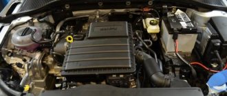
Design
Most often, the injection pump is located in the space under the hood near the power unit. For most foreign-made diesel engines, the fuel supply system pipelines from the pump to the injectors are made of metal, which also reduces the number of possible places for their installation. The design of this unit includes two main elements: a small-diameter cylinder and a piston (plunger) located in it, which together form a plunger pair. This pump element is made of high-quality steel, capable of withstanding high pressure loads, and requires maximum precision in production, since for the plunger pair to operate, it is necessary to ensure a minimum gap between its parts (precision mating).
The intermediate element that directly connects the fuel injection pump with the cylinders is the nozzle, which is located with its lower part in the combustion chamber and sprays a portion of fuel. The exact timing of ignition is adjusted by the advance angle and controlled by the vehicle's electronic systems.
Varieties
The design of modern diesel engines uses several types of high-pressure fuel pumps (HPFP).
Row
This type of design is characterized by reliability and long service life. Pumps of this class are lubricated with engine oil, which ensures their compatibility with low-quality diesel engines. In-line designs are installed on power units with separate combustion chambers and are equipped with plunger pairs in accordance with the number of cylinders. The pump pistons are driven by a cam shaft, which is connected to the engine crankshaft. Permanent pressure of the plunger against the cam is ensured using springs. The system has the following operating principle: rotation of the cam shaft moves the piston, which closes the intake and exhaust channels. At the same time, the pressure in the chamber increases, opening the discharge valve and a portion of fuel is sent to a specific nozzle.
Electronics are responsible for dosing the volume of fuel in new models, but in older engines this property was ensured by turning the piston a certain number of degrees inside the cylinder. The mechanism responsible for this operation was a gear connected to a rack and connected to the gas pedal. Injection adjustment when pressing the accelerator changed was carried out through a clutch with weights that diverged under the influence of centrifugal force and provided the required advance angle, depending on engine speed.
Distribution
This design is characterized by smoother and more stable operation, as well as smaller dimensions compared to the previous version. Distribution-type high-pressure fuel pumps include the following modifications:
- Rotary or plunger
- With internal, end or external cams
This design option is equipped with a pair of plungers that serve all combustion chambers. In this case, the pistons make a number of revolutions equal to the number of cylinders in a particular engine, which causes a permanently high level of load on the parts and their accelerated wear, relative to in-line analogues.
Trunk
This type of design is characterized by the best controllability of ignition processes among existing analogues and is used in engines with a Common Rail system. Maximum control over the combustion of the mixture is ensured by supplying diesel not directly to the combustion chamber, but to a ramp (main), which acts as a preliminary accumulator. This technological solution made it possible to separate the processes of injection of the mixture and the formation of the required pressure. The operation of the pump is controlled by electronic control systems.
Injection pumps of this type have the greatest efficiency and are considered the pinnacle of evolution in their class. Different engine models use pumps with different numbers (from 1 to 3) plunger pairs. In addition, the system can be equipped with a hydraulic drive that supplies fuel through special valves. This design solution allows you to most accurately adjust the dosage.
Bosch injection pump repair
The high pressure fuel pump (HPFP) is the heart of the Common rail fuel system. The common rail fuel injection pump is much simpler in design and functionality than its predecessors. Its main function is to constantly supply fuel to the rail under high pressure.
Pumps come in different types. The main distinguishing characteristics are the performance and design of the pumps themselves, which determines their capabilities and applications.
In the Common rail fuel system, fuel is supplied according to the scheme: fuel tank → pumping device → creation of high pressure in the injection pump. Therefore, for the normal operation of the fuel system, the effective operation of both the booster pump (booster pump) and the fuel injection pump itself is equally important. The booster pump can be either electric or mechanical. Some are installed inside the tank, some are installed at the outlet of the tank. In the CP-3 type fuel injection pump, the gear boost pump is integrated directly into the fuel injection pump housing.
Injection pump device diagram
a) longitudinal section:
1 - drive shaft; 2 - eccentric cam; 3 - plunger with bushing; 4 - chamber above the plunger; 5 — inlet valve; 6 — solenoid valve for shutting off the plunger section; 7 — exhaust valve; 8 - seal; 9 — fitting of the line leading to the high-pressure accumulator; 10 — pressure control valve; 11 - ball valve; 12 — fuel return line; 13 — fuel supply line to the injection pump; 14 - safety valve with throttle hole; 15 - low pressure bypass channel.
b) cross section:
1 - drive shaft; 2 - eccentric cam; 3 - plunger with bushing; 4 — inlet valve; 5 — exhaust valve; 6 - fuel supply.
Principle of operation
The principle of operation of the injection pump is that pumping feeds it with the necessary low pressure (depending on the type of system, this is 4-7 Bar). After which, the diesel fuel enters the low pressure bypass channel. When the plunger is lowered, a vacuum in the chamber above it occurs, and fuel is drawn in from the low pressure channel through the inlet valve. When the plunger moves back, fuel is pumped into the outlet valve. Since the valve opening is much smaller than the supplied fuel flow, very high pressure is created at the valve outlet.
The pressure produced by the injection pump in the Common rail system can reach about 1200-1400 Bar, in some cars more than 2000 Bar. Pressures above 2000 Bar are used mainly in new generation cars, where fuel injection occurs using piezoelectric injectors. Their design allows, at this pressure, to supply a powerful portion of fuel in a very short period of time, while dividing it into 4-5 parts. This makes the engine run quieter and cleaner, while also making the engine feel more responsive.
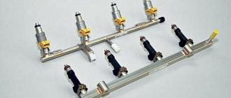
Fuel rail
Since the pressure in the pump increases through the alternate operation of plunger pairs, it comes out “intermittently” at the output. To dampen these vibrations, a fuel rail (rail) is installed in the system. A ramp is a high-pressure reservoir in the form of a pipe into which fuel is supplied from a pump. Its main tasks are: accumulating fuel, holding it under high pressure, damping pressure fluctuations and distributing fuel among the injectors.
There is a pressure sensor on the ramp for monitoring the system by the control unit. And to regulate the system for high pressure, an electromagnetic pressure reducing valve is installed on the rail. When at rest, it passes fuel through itself into the drain line. When a signal is sent from the vehicle's ECU (control unit), it begins to hold fuel in the ramp, according to the mode assigned to it.
In other car models, the role of a pressure regulator is performed by a dosing unit (low pressure regulator) integrated into the fuel injection pump; in some systems both types of regulators coexist. As a result of this interaction between the elements of the fuel system, diesel fuel enters the injectors under the required pressure.
Failure of the high pressure fuel pump
The main reason for fuel injection pump failure is poor quality fuel, service life and operating conditions. Common rail pumps are very demanding on the cleanliness and quality of the fuel.
Let's consider a common version of the fuel injection pump - SR1 . Such pumps are installed on cars and minibuses of Mercedes, BMW, Fiat, Peugeot, Citroen, Iveco. The design of such a pump is quite simple: drive shaft, eccentric cam, 3 plungers, 3 valves. All this is mounted in a three-head housing. An electromagnetic valve for shutting off the plunger section is installed on one of the pump head covers. Sometimes pumps are equipped with a pressure regulator.
What could happen to such a simple and unpretentious pump? Indeed, you can’t expect any difficulties from him. There are two main problems - leakage and low performance.
Flow
Such a pump leaks due to failure of the sealing seals. Less commonly, this occurs due to microcracks in the pump head cover. As a result, the fuel injection pump begins to “get wet”. This defect is more pronounced when the engine is cold; often, after the engine warms up, the pump stops flowing. This suggests that it is time to change these same sealing seals. If there are microcracks in the cover, it must be replaced. A pump leak is unpleasant because diesel fuel gets onto the belt, which gradually becomes wet and, as a result, it breaks.
Poor performance
The performance of the CP1 injection pump depends on the valves, plungers and the condition of their precision parts. If the normal operation of the valves is disrupted, they cannot pump up the specified pressure in the required period of time. In this regard, the following defect is often encountered: when the car accelerates smoothly, it works normally and develops speed, but when it accelerates sharply, it enters emergency mode (the speed drops, and in some models it even stalls).
This happens when overtaking, which is not only unpleasant, but also very risky, when a car in the oncoming lane suddenly cuts off and you have to desperately look for a way out of this situation. This breakdown is more noticeable on a hot engine and in hot weather.
Injection pump repair algorithm
After cleaning, the pump is checked for mechanical damage. Then we open the flange and assess the internal condition of the injection pump (chips, rust, dirt residues). If everything is in order with this, the injection pump goes to a bench test. The pump is tested in different modes at different loads. As a result of the inspection, its malfunctions are determined, after which a decision is made to repair it. Repairs, as a rule, are of two types: replacing the repair kit (if a leak is detected) or replacing valves in case of low fuel injection pump performance. All repair components are manufactured by Bosch.
Warranty for fuel injection pump repairs
For complex repairs of fuel injection pumps, a guarantee is provided. Read more about this here.
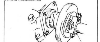
Principle of operation
The high-pressure fuel pump (HPF) circuit of a diesel engine includes a piston and a discharge valve. Receiving an impulse from the crankshaft of the power unit through the transmission, the cam shaft rotates and “runs” onto the clutch, which moves towards the nozzle, increasing the pressure in the portion of fuel above the piston. At the same time, the intake tract is closed. After reaching the required degree of pressure, the discharge valve opens and diesel enters the nozzle. During the downward movement, the remaining fuel is removed through a screw channel cut into the plunger body. In this case, the cavity in the piston at a certain moment is at the same level with the exhaust tract and the procedure is repeated.
Electronic units are responsible for controlling the fuel injection pump in modern power units. The equipment receives data from controllers for temperature, shaft rotation, coolant temperature, fuel temperature, etc., based on which it generates command signals. Based on the optimal operating algorithms stored in memory and incoming information, electronic units regulate feed cycles and advance angle.
Depending on the specific engine, its design may include additional components designed to control the operation of the pump.
Repair of classic fuel injection pump systems
\ Moscow region, Solnechnogorsk district, 68th km. highways Moscow-St. Petersburg, pos. Smirnovka, Industrial Zone Tel, (915) 187 89 88 Email: This email address is being protected from spambots. Javascript must be enabled in your browser to view the address.
Attention! The given cost of work is not a public offer and may differ from those currently in force.
Repair and adjustment of in-line injection pumps
| № | NAME OF WORKS | Price in rub. |
| 1 | Injection pump washing (mandatory service) | 250.00 |
| IN-LINE FUEL PUMPS | ||
| 1 | Checking injection pump BOSCH/ZEXEL/DENSO (A,MW,P) up to 8 sections inclusive | 2300.00 |
| 2 | Adjustment of injection pump BOSCH/ZEXEL/DENSO (A,MW,P) up to 8 sections inclusive | 4500.00 |
| 3 | Checking injection pump BOSCH/ZEXEL/DENSO (A,MW,P) more than 8 sections | 4500.00 |
| 4 | Checking BOSCH fuel injection pump up to 8 sections with EDC | 5600.00 |
| 5 | Repair of injection pump BOSCH/ZEXEL/DENSO (A) 4-section | 7000.00-10000.00 |
| 6 | Repair of fuel injection pumps BOSCH/ZEXEL/DENSO (A,MW,P) up to 8 sections inclusive | 10500.00 |
| 7 | Repair of BOSCH injection pump up to 6 sections with EDC | 11500.00 |
| 8 | Repair of injection pump BOSCH 8 sections with EDC | 12500.00 |
| 9 | Repair of injection pump BOSCH H-series (2 rack) up to 6 sections with EDC | 13500.00 |
| 10 | Repair of injection pump BOSCH H-series (2 rack) 8 sections with EDC | 15500.00 |
| 11 | Disassembly and troubleshooting of BOSCH/ZEXEL/DENSO fuel injection pumps without assembly | 2500.00 |
| FUEL DISTRIBUTION PUMPS | ||
| 1 | Checking the BOSCH/ZEXEL/DENSO VE injection pump on a stand | 2000.00 |
| 2 | Checking the BOSCH VE injection pump with a mechanical regulator on a stand (with adjustment) | 3500.00 |
| 3 | Checking the BOSCH VE injection pump with electronic control on a stand | 3000.00 |
| 4 | Checking the BOSCH VE injection pump with electronic control (with adjustment) | 4500.00 |
| 5 | Disassembly and troubleshooting of BOSCH/ZEXEL/DENSO fuel injection pumps without assembly | 1500.00 |
| 6 | Repair of BOSCH VE injection pump with mechanical regulator (with adjustment) | 5500.00 — 10000.00 |
| 7 | Repair of BOSCH VE fuel injection pump with electronic control (with adjustment) | 5500.00 — 10000.00 |
| 8 | Specialist. Equipment and tractors of domestic and imported production | 5000.00 — 9000.00 |
| 9 | Fuel injection pump 4UTNI and their models (YaMZ, PAZ, MTZ, GAZ, DT-75, ZIL, Bychok) | 5000.00 — 7000.00 |
| 10 | Block injection pumps for refrigeration units (Yanmar, Kubota, Zexel, Bosh) | 2500.00 — 8700.00 |
| INJECTORS | ||
| 1 | Checking a single-spring injector on a stand (mechanical) (for 1 pc.) | 50.00 |
| 2 | Adjusting the single-spring nozzle on the stand (for 1 pc.) | 150.00 |
| 3 | Checking the double-spring nozzle on a stand (for 1 pc.) | 50.00 |
| 4 | Checking the injector (stage holder) MB Actros, Atego, etc., MAN TGA (mechanical) (for 1 pc.)*** | 100.00 |
| 5 | Repair of nozzle with adjustment (per 1 pc.) | 350.00 |
| 6 | Repair of double-spring nozzle with adjustment (for 1 pc.) | 450.00 |
| 7 | Repair of injector (step holder) MBActros, Atego, etc., MAN TGA (for 1 pc.) | 450.00 |
- When handing over a dirty injection pump for repair, a fee of 250 rubles will be charged. for pump cleaning.
- The warranty period for work performed and spare parts is 6 months.
- The warranty does not apply to spare parts provided by the client or as agreed.
- When repairing the fuel injection pump, diagnostics are free.
- The price for repairing injection pumps BOSCH, ZEXEL, DENSO is indicated without taking into account the cost of spare parts.