Functional features of plunger pump
Plunger pumps belong to the category of hydraulic devices of the metering type.
This design allows you to dose and mix the various components of solutions in the required ratio. In accordance with the design features, this category of pumps is divided into two groups: volumetric and non-volumetric. Positive displacement plunger pumps are similar in functionality and operating principles to piston pumps. The main difference lies in the design of a special piston - plunger. This unit is presented in the form of a metal rod with a reciprocating motion. There is no contact with the walls of the working chamber of the pump. As the main working element of the pump, the plunger must meet certain requirements, namely, to be durable, leak-proof and wear-resistant.
The specificity of the operation of a plunger pump lies in the direction of movement of the plunger. When the unit moves to the right, the pressure inside the working compartment decreases while maintaining consistently high values in the suction pipeline. With such a pressure difference, the suction valve is activated, through which the solution passes into the working chamber. When the unit moves to the left, the reverse process occurs and the solution is forced out of the working chamber.
When changing pressure levels in a plunger pump, pulsation may occur. This may negatively affect the performance of the device, so it is recommended to eliminate this problem. You can resort to the use of several plungers connected by a shaft and moving in a cyclic mode. Differential operation of the device is also possible when liquid is pumped in any direction.
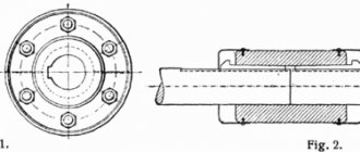
High pressure fuel pump (Fig. 43) - designed to supply fuel through a nozzle into the diesel cylinders under high pressure in a certain quantity and at a strictly defined moment. The diesel engine is equipped with six identical plunger-type fuel pumps, each through a boss attached with four bolts to the upper horizontal sheet of the camshaft compartment.
· Injection pump device. All pump parts are housed in a hollow housing 23
, cast from special magnesium cast iron.
In the upper part of the body there is a thread (M48) for the pressure fitting 11
.
Below, several borings of different diameters are made, forming a cavity for fuel and an annular flange for the sleeve 16
.
In the housing wall there is threaded hole (M22) for fitting 25
, and in the side boss there is
a horizontal hole with a diameter of 16 mm
for gear rack
6
.
At the bottom of the housing there is a rectangular flange b with four holes and a cylindrical protrusion a with a diameter of 85 mm
, which ensures alignment of the pump with the boss
13
(see Fig. 44).
Above flange b (see Fig. 43) in the pump housing there is a control window b used during repairs.
A steel sleeve 16
, sealing it with an aluminum ring
7
.
The sleeve is secured against rotation with a pin 18
pressed into the body, for which purpose
a groove r
is milled mm . The upper part of the liner is thickened (outer diameter 45 mm
and inner diameter 20
mm
), since high fuel pressure is created in it when the pump operates.
Two radial holes with a diameter of 6 mm
with conical bores at the ends serve to pass fuel into the liner.
The housing is installed on top of the end of the liner with lapping. 8
9
ground into it .
In the lower part, the discharge valve has four guide feathers e , the cylindrical surface of which is ground into the body 8
, and in the upper part there are two belts.
The conical belt h is ground into the seat, and the cylindrical belt w , which is the unloading belt, is ground into the valve body 8
.
The discharge valve is pressed against the housing seat 8
spring
14
installed in the bore of the pressure fitting
11
screwed into the pump housing.
A steel sealing ring
15
between the fitting 11
and the housing
8 , and the fitting is sealed relative to the housing with a rubber ring
10
installed in a groove on its outer surface.
At the top, the fitting has a threaded shank (M22) for a union nut 12
for fastening a high-pressure pipeline
13
.
Rice. 43. High pressure fuel pump:
1
,
4
— retaining rings;
2
- lower plate;
3
,
14
- springs;
5
- locking screw;
6
— toothed rack;
7
,
15
- sealing rings;
8
— discharge valve body;
9
— discharge valve;
10
— rubber ring;
11
- pressure fitting;
12
- union nut;
13
- high pressure pipeline;
16
— sleeve;
17
- plug;
18
— pin;
19
— rotary sleeve;
20
- upper plate;
21
- glass;
22
- plunger;
23
- pump housing;
24
— fuel supply pipe;
25
- fitting;
a , o - protrusions; b - flange; c — control window; g , d , s , y - holes; e - feather; g , h - discharge valve bands; and - annular groove; k - vertical groove; l - cutting edge; m - guide part of the plunger; n - labyrinthine groove; p - shank; p —groove; t - ring gear; f - groove; A - annular cavity.
22 ground into it is inserted into the sleeve from below.
, which is a cylindrical rod made of high quality steel and heat treated.
On the upper part of the plunger (head), which has a diameter of 20 mm
,
a vertical groove with a width of 4 mm
.
is from the top from the groove to the annular recess , forming a cutting edge l . The end and spiral edges of the plunger must be sharp. On the guide part the a labyrinthine groove with a width of 2 mm
is machined , which reduces the leakage of fuel along the plunger.
In the lower part, the plunger has protrusions o and ends with a cylindrical shank n .
The sleeve together with the plunger forms a precision pair, processed with a high degree of accuracy (the gap between the mating parts is 1.5-2.5 microns). If the sleeve or plunger is faulty, the complete set must be replaced.
A rotary sleeve is placed on the sleeve with a gap from below 19
, in the upper part of which there is
a gear ring t , which engages with a gear rack 6
installed in the pump housing.
A groove is made on the cylindrical surface of the rack for a locking screw 5
, which limits the longitudinal movement of the rack and prevents its rotation.
Screw 5
is screwed into the inclined hole of the pump housing.
The rotary sleeve in the lower part has slots into which the protrusions on the plunger fit.
Thus, the rotary sleeve allows the plunger to reciprocate and at the same time rotates it as the rack moves. 3 is used to move the plunger down
, sandwiched between two plates.
The upper plate 20
is put on the rotary sleeve
19
and is held by a split retaining ring
4
installed in the groove of the body.
The lower plate 2
has a radial slot and is put on the lower part of the plunger, resting against its
shank p .
21 is inserted into the pump housing from below
, transmitting force from the fuel pump pusher to the plunger.
The movement of the glass is limited by a split retaining ring 1
installed in the groove of the pump housing.
On the outer surface of the glass there is an annular mark, used when checking the moment the fuel supply begins, and in the bottom there are four holes with a diameter of 10 mm
for draining leaked fuel.
· Fuel pump pusher (Fig. 44, a
) - transmits force from the camshaft cam to the fuel pump plunger.
Pusher 19
made of high quality steel and has a cylindrical shape.
annular grooves b are machined on its outer surface , connected by two vertical grooves a , which ensures lubrication of the pusher when it moves in the housing 18
.
In the lower part of the pusher there is a slot for a roller, loosely mounted on pin 20
.
Hollow finger 20
in design and installation it does not differ from the valve drive pusher pin.
The roller consists of two rings - internal 25
and external
24
, between which there is a gap of 0.02-0.06
mm
.
On the inner surface of ring 25
there is
a groove 3 , from which oil flows through four radial holes with a diameter of 3.5 mm
to lubricate the contact surface of both rings. This design of the roller provides it with increased strength under conditions of high speeds of movement of the fuel pump pusher, which is due to the geometric shape of the camshaft fuel cam.
Rice. 44. Fuel pump pusher ( a
) and plunger position
with different fuel supply ( b
):
1
— side sheet of the block;
2
- camshaft;
3
- fuel cam;
4
- square;
5
- flange;
6
- top horizontal sheet;
7
- plate;
8
- glass;
9
- plunger;
10
— fuel pump housing;
11
- spring;
12
- reflective nut;
13
- boss;
14
- drain tube;
15
— Gufero oil seal;
16
— adjusting bolt;
17
— lock nut;
18
— pusher body;
19
— pusher;
20
- finger;
21
— bar;
22
- bolt;
23
— retaining ring;
24
- outer ring of the roller;
25
— inner ring of the roller;
26
— sleeve;
a - vertical groove; b – hexagon; c , d , h - grooves; d , g , i - holes; e - boss protrusion.
16 is screwed into the pusher from above
.
The hexagon b on the cylindrical shaft of the bolt allows you to screw the bolt in or out, adjusting the moment at which the fuel supply begins. After adjustment, the position of the bolt is fixed with a lock nut 17
.
The adjusting bolt passes through the central hole of the boss 13
, cast from an aluminum alloy.
With its cylindrical protrusion with a diameter of 80 mm
, the boss fits into the hole in the upper horizontal sheet
6
of the camshaft compartment.
A cylindrical deflector nut is screwed onto the top of the adjusting bolt. 12
, which, together with
the protrusion e of the boss, forms a labyrinth that prevents fuel from getting into the oil. In addition, fuel leakage through the bolt is prevented by the oil seal 15
, installed below in the boss bore and secured in it with a retaining ring
23
.
To fasten nut 12
on its outer surface, four blind holes are made for the protrusions of a special key.
The fuel that has leaked into the boss is discharged through
the hole and tube 14
into the clean fuel drain manifold.
The pipe 14
is flared in a strip
21
, which is attached to the boss with two bolts
22
.
If tube 14
, fuel from the boss flows through two
side holes d onto the top sheet 6
, enters
groove d and is discharged from it into the dirt container of the fuel tank.
· Fuel pump operation. Annular cavity A
(see Fig. 43) between the pump housing
23
and the sleeve
16
is constantly connected to the fuel manifold through a tube
24
and a fitting
25
, and therefore filled with fuel under a pressure of 0.20 - 0.25 MPa (2.0 - 2.5 kgf /cm2).
When the plunger moves downward under the action of the return spring 3
, fuel from the manifold through two radial holes
in
the sleeve enters the space above the plunger.
When the fuel cam runs up 3
(see Fig. 44,
a
) of the camshaft
2
on the roller, the pusher
19
begins to move upward and, with its adjusting bolt
16
, acts through the glass
5
on the plunger
9
of the fuel pump.
The stroke of the plunger at any speed of rotation of the diesel crankshaft is the same and is equal to 20 mm
, since it depends only on the size of the cam
3
.
The cam profile provides significant acceleration to the moving plunger. Part of the plunger stroke (30 - 40%) is spent on its acceleration, accompanied by the displacement of a certain amount of fuel from the space above the plunger back into the manifold through holes c (see Fig. 43).
At a speed of 0.4 - 0.8 m/s
The plunger with its end edge covers both holes
in
the sleeve.
Since with further movement of the plunger the volume of the space above the plunger quickly decreases, the fuel pressure in it increases sharply. When the force created by the fuel pressure above the plunger becomes greater than the force of the spring 14
and the residual pressure in the discharge pipeline, valve
9
opens and fuel is pumped into the high pressure pipeline
13
.
Fuel injection occurs until the edge L of the plunger opens one hole in the sleeve and thereby communicates the space above the plunger with the fuel manifold.
The fuel pressure above the plunger drops sharply, despite the continued upward movement of the plunger. Discharge valve 9
closes.
As soon as the lower edge of the cylindrical relief belt the valve enters the housing 8
, the communication of the high-pressure pipeline
13
with the chamber above the plunger stops.
When the valve is further seated with the conical belt 3 against
the seat, some unloading of the pipeline
13
from the high residual pressure due to the release of a small volume when the valve is seated.
Fuel exits from the space above the plunger through the radial hole C into cavity A
at the end of the discharge stroke it occurs at a very high speed, which leads to local cavitation damage to the pump housing.
Therefore, a replaceable
17
is screwed into the housing 23 .
The amount of fuel supplied by the pump depends on the duration of its pumping by the plunger, which is determined by the pumping stroke, i.e. the distance between the end and spiral edges of the plunger, measured along the axis of the hole
c . The fuel supply is regulated by a combined diesel regulator, which, by moving the racks, forces the bushings 19
to rotate the plungers
22
of the high-pressure pumps.
On (Fig. 44, b
) shows three different positions of the plunger
9
relative to the sleeve
26
.
In position / (zero fuel supply), the discharge stroke is zero, i.e. the space above the plunger is permanently connected to the hole in the sleeve through a vertical groove on the plunger head. In position // (middle fuel supply), the plunger is rotated at a certain angle and has a discharge stroke.
In position /// (maximum fuel supply), the plunger is rotated to the greatest angle, i.e. discharge stroke is maximum. · Connection of fuel pump racks to the control shaft. (Fig. 45).
Control shaft 1
fuel pump rails consists of three parts, rigidly connected to each other.
the protrusion at the end of one part of the shaft is inserted into the end groove d of the other part, after which both parts of the shaft are additionally secured with a clamp 11
, tightened with two bolts
9
.
The shaft is mounted on seven racks 13
, each of which is fixed with two pins and secured with two bolts on the upper horizontal sheet
12
of the camshaft compartment.
7
are pressed into the bores of the racks , reinforced with retaining rings
8.
The front end of the shaft
1
is connected to the integrated diesel regulator by a slip rod, and on the opposite side the shaft is connected to the limit regulator by a gear coupling.
Two clamps are mounted on the shaft against each pump. Right clamp 14
torsional
spring
15 4
freely mounted on the shaft.
The bent ends of the spring fit into the holes of the driver 4
and the clamp
14
.
The driver is pivotally connected by means of a pin 22
to the gear rack
21
of the fuel pump, for which the upper end of the driver is made in the form of a fork.
Pin 22,
together with the rack
21,
is inserted from above into the cutouts of the fork.
Flat cuts at the ends of the finger do not allow it to move along the axis. At the bottom of the leash there is a protrusion with a hole for an adjusting bolt 16
.
Rice. 45. Connection of fuel pump rails:
1
— fuel pump control shaft;
2
- head;
3
- fuel pump;
4
- leash;
5
— clamp;
6
,
9
,
17
- coupling bolts;
7
- ball bearing;
8
— retaining ring;
10
— washer;
11
- clamp;
12
— upper horizontal sheet of the camshaft compartment;
13
- stand;
14
,
18
- right and left clamps;
15
,
20
— springs;
16
— adjusting bolt;
19
- nut;
21
— gear rack;
22
- finger;
a , b , c - protrusions; g - groove.
Left clamp 18
, like the right one, is rigidly fixed to the shaft using a coupling bolt
17
.
The clamp 18
has
a cylindrical protrusion b with two flat cuts on the outer surface. A spring 20
and a retainer
5
, onto the threaded end of which a nut
19
to secure the head
2
. For ease of use, the cylindrical surface of the head is grooved.
Under the action of a spring 20
the clamp
5
comes out of the clamp
18
and rests on the end of the adjusting bolt
16
, which must be adjusted so that when the diesel engine is not running, the output of the rack is equal to the “Stop” dimension stamped on the fuel pump housing.
Spring 15
twists when adjusted. The position of the adjusting bolt is fixed with a nut and then sealed.
When the combined diesel regulator turns the shaft to increase fuel supply, the left clamp 18
through the clamp
5
presses on the adjusting bolt
16
, turning the driver
4
, which extends the fuel pump rail
21
.
When the shaft turns in the other direction, the right clamp 14
acts
through the
15 4
, moving the rack
21
to reduce the fuel supply.
The tightening of the spring 15
does not change in either case, since the spring rotates together with the clamps
14
and
18
.
To turn off the pump, the lock 5
using head
2
, they are moved away from the adjusting bolt
16
, overcoming the force of the spring
20
, and turned at an angle of 90°.
In this position, the head rests against the end of the protrusion b , holding the latch. The released driver, under the action of spring 15
, moves the fuel pump rack to zero fuel supply. Subsequently, turning the shaft does not cause any movement of the rack.
Types of plunger pumps
Water plunger pumps operate on the same principle as most other pumps. The pumped volumes depend entirely on the internal pressure - the higher its level, the greater the capabilities of the device.
Depending on the design features, there are different types of pumps:
- vertical and horizontal; - single and multi-plunger; — with control in manual or automatic mode; — with and without a heating jacket; - single and multi-cylinder; - with cylinder sealing.
The high-pressure pump category works with liquids of various properties, so they are made from materials that are suitable for the given environment.
Plunger pairs
12 best high-pressure washers
Since the plunger pairs in a distribution-type pump do more work than in a sectional pump at the same rotation speed, to bring the pump service life closer to the required one, it is necessary to select plunger-section housing pairs with a gap of only 1 micron, and plunger-dispenser - 0 3 microns. Such small gaps determine the high demands placed on the quality of the fuel used and especially on its separation from the water dissolved in it. The ingress of water deprives precision parts of mobility, which leads to pump failure.
Paired and mutually lapped plunger pairs are subjected to hydraulic testing and sorted into hydraulic density groups. The group is indicated on the outer surface of the sleeve.
The technical condition of the plunger pairs on a diesel engine is checked using a maximeter (a device similar to an injector with an easily adjustable injection pressure according to the scale on it) or a control injector adjusted to an injection start pressure of 30 MPa. If the plunger pair provides fuel supply at a pressure of at least 30 MPa, then it is fully operational.
Hydraulic stands are also used to test plunger pairs. The test pair is installed in the receiver of such a stand and clamped with a pneumatic cylinder rod. With the help of a hydraulic cylinder, the plunger rises; The ascent time is measured with a stopwatch.
The sleeves 43 of the plunger pairs are pressed through the collars of the seats 6 of the discharge valves 8 to the ends of the recesses in the pump head by fittings 10, which simultaneously serve to connect high-pressure pipes. A driver 18 is pressed onto the lower end of the plunger and fits into the groove of the rack clamp. Using a leash, the plunger rotates when adjusting the amount of fuel supplied.
| Device for disassembling fuel pumps. |
Replace parts of plunger pairs that have the following defects: chipping and chipping of the end and inclined edges of the plunger head; one-sided and local rubbing of the surfaces of the plunger pairs; deformation (riveting) of the plunger end; corrosion and fracture of the plunger, traces of scuffing; corrosion on the working surface of the plunger or bushing; crack in the bushing body. Corrosion on the end of the plunger or bushing is cleaned.
When checking plunger pairs by crimping them, you can use a dynamic or static method. When dynamic pressure testing is used, a constant load pressure is transferred to the plunger and the time of squeezing the liquid through the gap of the plunger pair is checked.
To check plunger pairs, manual hydraulic stands are also used.
When the plunger pairs are restored by chrome plating, their wear resistance increases significantly. At the same time, a significant disadvantage of this method is the uneven thickness of the coatings on the plungers, the formation of so-called fungi, which reach a thickness of 5 - 6 microns. In this regard, subsequent mechanical processing of chrome-plated plungers is very complicated, which significantly increases the cost of restoring plunger pairs by chrome plating and reduces the economic efficiency of their restoration.
Operational tests of plunger pairs restored by chemical nickel plating indicate that their service life tla is not lower than the service life of serial parts.
A decrease in the density of the plunger pairs worsens the uniformity of fuel supply to the cylinders, and there is a delay in the start of injection.
Before testing plunger pairs for density, the correctness of the test bench readings is checked against the readings of the reference plunger pair. Standard plunger pairs are used when using fuel with non-standard viscosity and temperature.
| Device for testing plunger pairs of a fuel pump for leaks.| A device for testing plunger pairs of a fuel pump for tightness at variable pressure. |
When testing plunger pairs of pumps whose parameters are unknown, it is recommended to first test the reference 1 pair (new, serviceable), and then any working one.
Plunger - hydraulic cylinder
During the working stroke, the plunger of the hydraulic cylinder 18 first compacts the material newly poured into the material cylinder, and then pumps it into the injection mold. Thus, as the plunger moves, it overcomes resistance and consumes high-pressure working fluid. Unlike cylinder 18, the plunger of cylinder b does not encounter resistance during its movement and therefore does not require high-pressure fluid; the need for it arises only at the moment of closing the injection mold.
The plunger of a hydraulic cylinder with an external seal is designed as one piece, and with an internal seal, for ease of changing it, it is made of two parts: a body and a head. To lighten the weight, the plunger is usually made hollow. The outline of its bottom should correspond to the shape of the bottom of the cylinder.
Under the action of the plunger of hydraulic cylinder 3, the tray moves in the transverse direction. In this case, the slide plate 4 located under the tray experiences vibrations in the direction perpendicular to the movement of the tray. Due to the movement of the tray and the vibration of the slide plate, the tablets are reloaded through the slot of the tray into the slots of the slide plate. After resting on the mold, the gate moves relative to the gate plate so that their holes coincide, and the tablets are loaded into the cavities of the mold.
| Multiplier diagram. |
The rolling pin 3 is the plunger of the hydraulic cylinder 4 of the multiplier, which supplies water to the press.
| Gear cage of four-leg mill 2BOO. |
The upper roll with cushions is suspended from the plunger of a hydraulic cylinder installed in the upper part of the frame. When the pressure screws move upward, the upper roller rises under the influence of fluid pressure on the hydraulic cylinder plunger. As the pressure screws move downward, the top roll is lowered under pressure greater than the pressure generated by the hydraulic cylinder. The hydraulic balancing device operates smoothly and its dimensions are small.
The piston rod of the pneumatic cylinder is also the plunger of the hydraulic cylinder. The amplifier is controlled by a pneumatic distribution valve.
The second part is fixed in the slider 2, moved by the plunger of the hydraulic cylinder. The spindle is driven by a 75 kW motor.
| Scheme of a vertical electric upsetting machine. |
The lower half of the contact is stationary, and the upper half, mounted on the plunger of hydraulic cylinder 3, presses the workpiece against it during the working cycle, which ensures reliable electrical contact.
There are two main types of moving devices: in the first type, the plungers of the hydraulic cylinders act directly on the press table (Fig.
A pneumatic piston accumulator differs from a cargo accumulator in that the action of the load on the plunger of the hydraulic cylinder is replaced by the force of the piston of the pneumatic cylinder. The disadvantages of this battery that limit its use include the presence of moving elements, lip seals and the cumbersome installation caused by the use of low pressure compressed air.
The plunger of the hydraulic cylinder installed at the middle rod is engaged with the small wheel by means of a rack and rotates the transmission shaft of the manipulator with gears, which transmit movement to the right rods of the manipulator and the racks. A gear mounted in the middle post moves the middle left rod through a rod and gears. The movement of the rack causes the gear mounted in the left post of the middle rod to rotate. This gear, through the transmission shafts, rotates the gears mounted in the left racks of the side rods and moves them longitudinally. All gears and racks are mounted in massive cast racks mounted on the foundation. The return of the manipulator rods to their original position is carried out by a counterweight, which is attached to the bottom rail by a rope thrown over a block.
The mechanism of the first compression stage consists of two hydraulic cylinders with plungers and one air cylinder with a piston. A stamp is attached to the front ends of the hydraulic cylinder plungers - a steel plate protected by a replaceable lining. The stroke of the plungers is 1000 mm. The stamp is returned to its original position using a single-acting air cylinder, the piston rod of which is pivotally connected to the central part of the stamp.
Metal plunger
| SBS plungers with soft sealing rings made of rubberized fabric. |
Injection pump device, types, principle of operation, adjustment and repair
Metal plungers perform a sealing function without additional sealing elements due to the selection of minimal gaps between the plunger and the cylinder.
| Diagram of a non-insert (pipe pump. |
Metal plungers are made in several designs (Fig. VIII.
The metal plunger of the pump is a pipe with a length of 1200, 1500 and 1800 mm with a chrome-plated surface, with a chrome thickness of 70 microns. The tolerance for the manufacture of the outer surface is accepted from 0 to - 0 03 mm and from - 0 02 to - 0 04 mm. The roughness of the rubbing surfaces should be no more than: for the plunger 0 25 microns and for bushings 0 32 microns.
Metal plungers are often made with annular grooves along the outer surface (Fig. Since hydraulic resistance increases under these conditions, the amount of liquid flowing around the plunger per unit time decreases. If there is sand in the liquid, the latter, getting into individual grooves, does not have an abrasive or scratching effect over the entire surface of the plunger, and therefore its service life is extended.
Pumps with a sleeve cylinder are equipped with a metal plunger, pumps with a sleeve cylinder and with sleeveless cylinders are equipped with a lip plunger. Cuff plungers are known in several designs. In the USSR, deep-well pumps are mainly used with a rubberized plunger, the rubber cuffs of which are shaped like rings and vulcanized to the plunger body. In the Soviet Union, deep-well pumps with a metal plunger are mainly used.
Pumps with metal plungers are manufactured with different clearances between the plunger and the cylinder. This makes it possible to select vacuum pumps in accordance with their operating conditions in the well.
Pumps with metal plungers of each standard size are manufactured with gaps of three sizes between the plunger and the pump cylinder, which characterizes the degree of fit or seating of the plunger in the pump cylinder.
Deep well pumps with metal plungers of all sizes are manufactured with gaps of three sizes between the plunger and the cylinder, which characterizes the degree of fit or fit of the plunger in the pump cylinder.
All pumps with a metal plunger and cylinder have standardized parts.
Most deep-well pump designs use metal plungers that are carefully ground and polished on the outside for a tight, movable fit in the cylinder. For bushing pumps, plungers are made from high-quality solid-drawn steel pipes. In severe operating conditions, in the presence of a corrosive environment, the plungers are chrome plated.
Thin-walled and thick-walled cylinders with metal plungers or plungers with soft seals are used. A version with a casing and cylindrical bushings is also possible.
The pumps consist of a solid fixed cylinder, a movable metal plunger, single suction and discharge valves and a pump mounting unit in the tubing.
Later, special pipeless pumps with a metal plunger with a diameter from 33/4 to 13/4 began to be produced, which significantly expanded the range of application depths for pipeless operation.