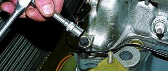
As you know, heated metal tends to expand. Parts of the gas distribution mechanism - valves, valve drive parts, camshaft - are all made of different metal alloys, and as the engine warms up, they increase in size. This is why there is a small gap between the camshaft and the valve lifter (or between the rocker arm and the valve) - it is called a thermal gap.
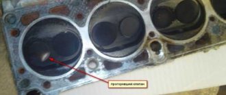
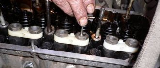
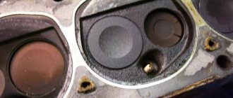
In order to more clearly understand the importance of the presence of a thermal gap, we will go from the opposite: let’s imagine that there is no thermal gap. Then, in a cold state in the valve drive, the parts will fit tightly together. As it warms up, the valve stem will lengthen. There is no gap at the top, which means it will lengthen downwards. This will cause the hot valve poppet to be loose against the seat (LINK) when closed. The gap will appear in an unnecessary place, and the air-fuel mixture will “leak” out of the cylinder through it, impairing the engine’s performance. The logical solution to the problem is to have a small gap at the top. At a comfortable above-zero temperature outside, it is difficult to “hear” the presence of this gap - both a cold and a hot engine will work approximately the same by ear. In severe frost, when the gap becomes larger, the running engine will work hard, with a characteristic knock. This is the sound with which the actuator impacts the valves. These symptoms should go away quickly. If the motor constantly runs as if it were cold, then most likely over time the thermal gap in it has increased to abnormal levels. In general, as the parts of the gas distribution mechanism wear out, the gap can either increase or decrease - it all depends on the specific design features of the engine and the quality of the metals from which the parts are made. The increase in clearance is caused by wear of the camshaft cams, valve ends and drive parts. Reducing the clearance means wear of the valve seats and discs (LINK) and, as a result, a deeper fit. To put it simply, if the camshaft and drive are subject to wear more than the seat and plates, then the clearance will increase. If it's the other way around, it will decrease. One way or another, periodically the thermal gap needs to be measured and, if necessary, adjusted. If the gap is too large, the shock loads on the valves will increase (and their wear will accelerate!), and in addition, the valves will not open completely, which will worsen the filling of the cylinders and reduce power. Too little clearance is also not good. The air-fuel mixture will leak into the gaps between the seats and loosely closed valves (i.e., the compression ratio and engine power will decrease), but worse than that: hot exhaust gases will pour into the channels and have a detrimental effect on the valves. The seats remove excess heat from the valves, so lack of contact with them can lead to overheating and deformation. The valve drive of the engines has an adjustment mechanism that allows you to adjust the amount of clearance. It differs from motor to motor, so within the scope of this article it is not possible to give an exhaustive description of the adjustment process. In addition, this is a rather difficult procedure that requires experience and tools, so it is better to entrust it to a trusted specialist.
As an illustration, let's look at the VAZ-2110 engine, where the size of the thermal gap is adjusted using a washer of the required thickness installed between the valve tappet and the camshaft cam.
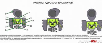
Additionally, it is worth saying that on many engines the thermal gap is adjusted automatically - using hydraulic compensators, which are described in detail in a separate article (LINK).
KnowCar is a clear encyclopedia on the design of cars, where complex things are described in simple language, with illustrations and videos, and articles are sorted into sections. The encyclopedia is in the process of being filled. If you have questions or suggestions, please contact the team. All contact details are at the bottom of the site.
While the cars that were included in the VAZ classic series, and these are models from 2101 to 2107 and Niva, will drive on the country's roads, their owners will have to learn how valve clearances are adjusted. These new machines are equipped with self-regulating hydraulic compensators, which independently adjust the operation of the gas distribution mechanism. The good old Zhiguli cars need more attention.
Why are valve thermal clearances set?
One of the most common types of adjustment work is adjusting the gas distribution mechanism, in particular the gap that should exist between the camshaft cams and the rocker (valve lever).
Many people have a question about what this gap is for? Wouldn't it be better to adjust the parts so that they just fit together as tightly as possible? The answer to this question is found in school physics textbooks, and more specifically in the section that talks about the thermal expansion of solids.
The fuel mixture, burning in the cylinder, heats all parts of the engine to a very high temperature. Naturally, all parts increase slightly in size. For the gas distribution mechanism, such an expansion can lead to negative consequences. The inlet and outlet valves must close the seat very tightly. If the valve stem rests rigidly in the upper part, then during thermal expansion, its plate will move down and the channel will be slightly open, and this leads to an undesirable result, namely:
- reduction and loss of engine power;
- increased fuel consumption;
- overheating and destruction of timing parts (valves, etc.) by escaping flames.
To ensure that the valve always remains closed during expansion, the thermal clearance of the valves is calculated. The gap is present when the engine is cold, but when its temperature reaches operating parameters, the gap gradually decreases. Naturally, the driver is interested in what valve clearance is set during adjustment. The gaps have a strictly established value - 0.15 mm. An adjustment error of 0.05 mm is allowed. This value is calculated for a cold engine. Adjustment on a hot engine is possible, but such adjustment is considered inaccurate.
- sustainable;
- fuel economy;
- increasing motor life.
What you need to prepare for regulation
Fearing that they will do something wrong, many car enthusiasts head to a car service center if they need to adjust the valves. Considering that such a procedure should be carried out, on average, after every 15-20 thousand kilometers, you have to pay a significant amount from the family budget. In addition, a lot of time is spent waiting in line at the service center, and the engine must cool down to the required temperature. Therefore, it is better to adjust the valve clearances yourself in a garage. This work is not difficult and you will need a simple tool for the operation:
- probe 0.15 mm thick;
- wrenches.
In order to begin work, you need to install the car in a well-lit place or install artificial lighting in the engine compartment. Next, you should disconnect the air filter housing, timing cover, and remove the oil dipstick.
Adjusting valve thermal clearances
To begin the process of adjusting the clearances, you should set the piston of the first cylinder to top dead center on the compression stroke. It's simple: use a wrench to turn the crankshaft until the drilling on the camshaft drive sprocket with welding and the marks on the crankshaft pulley and the engine block coincide.
Now you can start directly adjusting the gaps, and this is done like this:
- the probe is inserted between the working parts of the cam and the lever of the corresponding valve;
- if the feeler gauge enters with slight difficulty, we can assume that the gap is in normal condition;
- if the feeler gauge does not fit in, fits in very tightly or passes without any effort, you need to start adjusting: holding the head of the adjusting bolt with a 13 wrench, release the lock nut with a 17 wrench and turn the bolt in the desired direction until the required gap is obtained, check the height of the gap with a feeler gauge, then then tighten the locknut.
The first valves to be adjusted are the 8th valve (4th cylinder) and the 6th valve (3rd cylinder). The valves are adjusted in pairs, and for each of them the camshaft must be rotated 90° (crankshaft 180°). With each subsequent turn, the following valves are adjusted:
- No. 4 (2nd cylinder) and No. 7 (4th cylinder);
- No. 1 (1st cylinder) and No. 3 (2nd cylinder);
- No. 5 (3rd cylinder) and No. 2 (1st cylinder).
Perhaps on the first try you, as a novice auto mechanic, will not be able to make a perfect adjustment of the valve drive, but after some time, the adjustment skills will come by themselves. It is advisable that the work, especially for the first time, be supervised by an experienced mentor.
Even an experienced car enthusiast should definitely check the compliance of the technology for adjusting thermal gaps. This is done after all valves have been checked and adjusted. Using a wrench or hanging the rear wheel, you need to turn the crankshaft several times. After this, you should install the crankshaft and camshaft at the same marks and check the gaps according to the algorithm described above. If necessary, repeat the gap adjustment.
The thermal clearance of the valve ensures its tight fit on the seat during thermal expansion of parts during engine operation. For each engine model, the optimal value of the thermal clearance in the valve mechanisms is established.
During operation, due to wear or improper adjustment, the size of the thermal gap may change and deviate from the optimal dimensions. Both an increase and a decrease in the thermal gap negatively affects the operation of the timing belt and the engine as a whole.
With a very large thermal gap, shock loads increase, and wear of valve drive parts also increases. The valve timing is disrupted (the moment of the beginning and end of the opening and closing of the valve), which leads to a loss of engine power and efficiency.
Small thermal gaps do not ensure the tightness of the combustion chamber, causing the engine to lose compression, not develop full power, and the valves overheat, which leads to valve burnout.
The gaps are checked and, if necessary, adjusted during maintenance. in the timing belt is performed on a cold engine - 15-25 degrees Celsius. The clearance is adjusted using a feeler gauge, the thickness of which must correspond to the required clearance in the valves of the car engine being adjusted. The feeler plate, the thickness of which is equal to the required gap, should fit into the gap when pressed lightly.
Sequence of work when adjusting the thermal clearance of valves.
Remove the valve covers. We install the piston of the first cylinder at TDC during the compression stroke; for this it is necessary that the mark on the pulley coincides with the mark on the timing gear cover. The compression stroke can be determined in this way: unscrew the spark plug and insert a paper plug into the hole for the spark plug. Rotate the crankshaft with the crank until the paper plug comes out.
Using a feeler gauge, check the size of the thermal gap in the valves between the valve stem and the toe of the rocker arm. If the gap is not within the acceptable range, it must be adjusted. To do this, you need to loosen the lock nut of the adjusting screw; if the gap is small, unscrew the screw; if it is large, screw it in so that the feeler gauge of the required thickness can pass freely. While holding the screw, tighten the locknut. The dipstick that corresponds to the lower value should pass freely with little effort.
Rotating the crankshaft to an angle of 720/i, where “and” is the number of cylinders, adjust the valves in the other cylinders in the order of engine operation.
Reinstall the valve cover.
Start the engine, warm it up to 80-90 degrees Celsius and listen to its operation. If adjusting the thermal clearance of the valves
done correctly, there should be no knocking in the valves.
New cars have a special mechanism - a self-regulating hydraulic compensator, which is responsible for adjusting the operation of the gas distribution mechanism. But used ones will need to be given a lot of attention.
Why are valve thermal clearances set?
Several types of adjustment work are known, but one of the most common types is the adjustment of the gas distribution mechanism, or more precisely, the gap, the location of which should be between the rocker (valve lever) and the camshaft cams.
Many motorists are wondering why the manufacturer makes this gap in their car? Perhaps it would be better to adjust the parts so that the interval between them is as small as possible? You can find answers to such questions in a regular school physics textbook. Open the section that describes explanations regarding the expansion of bodies with increasing temperature.
When the fuel mixture burns in the cylinder, natural heating of absolutely all engine parts occurs, and to extremely high temperatures. Due to the increase in temperature, there is a slight increase in the size of the parts. Such expansion has an extremely detrimental effect on the gas distribution mechanism.
Both the intake and exhaust valves should be positioned as close to the seat as possible, closing it.
The valve stem may rest too hard on top, which will cause the valve plate to drop down when expanding due to a temperature jump. All this will lead to the channel opening, and the consequences of this phenomenon are extremely negative. Due to a slightly open valve, the following may occur:
1)
Reduce compression and engine power;
2)
Fuel consumption will increase;
3)
The PM parts (valves, seals, etc.) will overheat and be destroyed due to the escaping flame.
In order to force the valve to be constantly closed when expansion occurs, this thermal gap was created. It exists when the engine is cold, but when the engine warms up, reaching its normal operating parameters, this gap gradually decreases. Of course, the car owner may be curious about what the valve clearance should be when adjusting. These gaps have a strictly established value - 0.15 mm.
The permissible error during adjustment is
0.05 mm.
This size is designed for a cold engine. The adjustment can also be made when the engine is warm, although it is not a fact that the adjustment will be particularly accurate.
1)
Stable engine operation;
2)
Reduced fuel consumption;
3)
Increased motor life.
What you need to prepare for regulation
In order to prevent any mistakes, most car owners go to a car service to adjust the valves, leaving the car in the hands of professionals. If we take into account that such a procedure needs to be carried out approximately every 15 - 20 thousand km of the distance traveled, then you need to prepare a decent amount of money to pay for the services. Also be prepared to wait until it’s your turn at the service center and the engine of your car cools down to the required temperature. If you take these factors into account, it is better to adjust the valve clearances yourself. You won’t even need to leave the garage to do this. Collect the following list of necessary tools:
— a set of wrenches for the car;
Probe with a thickness of 0.15 mm;
Before performing work, you need to park the machine in a place where there is good lighting. You will also need to bring additional artificial light to After this, you will need to disconnect the air filter, or rather, its housing, the timing cover and remove the oil dipstick.
Adjusting valve thermal clearances
It is imperative that before adjustment, the piston of the first cylinder must be set at top dead center for compression. This is done very simply: you need to turn the crankshaft with a key so much that the drilling on the camshaft drive sprocket and the welding, as well as the marks on the engine block, coincide. After you have completed these preparations, you can proceed to the adjustment itself. The sequence of actions is as follows:
1)
It is necessary to place the probe between the working elements of the cams and the lever of the corresponding valve;
2)
If you feel a little resistance when inserting the feeler gauge, then know that the gap in your machine does not require adjustment;
3)
If you either cannot insert the probe at all, or it was very difficult to insert it, or the entry is too easy, then adjustment is necessary: the head of the adjusting bolt must be held with a “13” key, and at this time, with a “17” key, you need to loosen the lock nut and Turn the bolt in the desired direction until the gap reaches the desired size, then you need to check the height of the gap with a feeler gauge, and after that you need to tighten the lock nut.
First you need to adjust the 6th and 8th valves, these are the third and fourth cylinders, respectively. The adjustment is carried out in pairs, and for each valve in a pair, the camshaft must be rotated 90° (- 180°). Then, after each subsequent turn, you need to adjust the following valves:
1)
4th and 7th in the second and fourth cylinders;
2)
1st and 3rd in the first and second cylinders;
3)
5th and 2nd in the third and first cylinders.
Control check
There is a possibility that the first adjustment of the valve drive performed by you, a novice auto mechanic, will not be entirely ideal, but after a while, after gaining some experience, your skills will develop on their own. It is highly advisable that the first adjustment be carried out under the supervision of a specialist who can correct possible inaccuracies or malfunctions.
Even if you are an experienced car owner, it still makes sense to check the compliance of the gap adjustment technology. A similar procedure is carried out after completing the check and adjustment of each valve. Using a wrench or hanging the rear wheel, you need to turn the crankshaft several times. Next, you need to position the crankshaft and camshaft so that the marks on them match, and then you can check the clearance using the algorithm described above. If necessary, the check can be done again.
Of course, the hands of specialists will always do everything correctly, but they will ask for a considerable fee for the work. And if you learn to do certain things yourself, you can save a lot, which will lead to an increase in your family budget.
Subscribe to our feeds at
The normal operation of a car engine depends on many factors - temperature, oil pressure, correctly set ignition, etc.
Proper adjustment of the valve clearances is also of great importance; if it is not adjusted, various problems arise with the engine.
To correctly set thermal clearances, you need to know the adjustment procedure, the size of the gap between the valve and the pusher (adjusting screw or washer). This article will discuss what the adjustment procedure is for different models of passenger cars, what gaps should be set, nuances and characteristic features in regulation.
Procedure for adjusting valve thermal clearances
Almost all internal combustion engines of modern cars have a right-hand rotation of the crankshaft - the crankshaft rotates clockwise. The camshaft is driven from the c/shaft, and rotation is transmitted to the camshaft through a belt or chain. There can be several camshafts in an engine; how many there are in an engine depends on the design features of the power unit.
Each camshaft (CV) must have cams, which ensure the opening and closing of the valves and the filling of the internal combustion engine cylinders with the air-fuel mixture. In order for compression to be created in the cylinders, the valves in the cylinder head must be tightly sealed against their seats at the moment of closing.
There must be a thermal gap between the valve and the RV cam; it is measured when the valve is completely closed and the R/shaft cam does not press on the valve. For normal operation of the cylinders, the valves must be adjusted in accordance with the recommendations of the engine manufacturer, and each internal combustion engine model has a certain procedure for adjusting the valve thermal clearances (VTRZK).
PRTZK depends on:
- on the number of cylinders in the engine;
- cylinder operating order;
- specific engine model.
For example, the order of operation of the cylinders for many Russian internal combustion engines:
- four-cylinder – 1342;
- six-cylinder – 153624;
- eight-cylinder - 15426378.
But not all 4-cylinder internal combustion engines operate in the order indicated above, for example, the ZMZ-24/402 and UMZ-414/417/451 engines and some of their other modifications operate in the order 1243. Eight-cylinder V-shaped engines of the German concerns Audi/Volkswagen, BMW and Mercedes have a cylinder operating order of 15486372. It should be noted that passenger cars also have 2, 3, 5 and 12 cylinder internal combustion engines, respectively, they have their own cylinder operating order. The valves on the engines can be adjusted in different ways:
Working chamfer - seat - valve
| Lapped valve and seat surfaces. a is the width of the matte strip. |
Which VAZ engines bend valves.
3, when the timing belt breaks, does the engine bend the valve or not? The working chamfers of the valve seats are ground with abrasive wheels at the appropriate angle. For example, for the ZIL-130 engine, the intake valves are ground at an angle of 60, and the exhaust valves are ground at an angle of 45 to the axis of the guide bushings. The width of the working chamfer of the valve seat should be 2 5 - 3 0 mm for ZIL engines. In case of significant wear of the valve seat, when the sinking of the caliber exceeds the permissible value specified in the technical specifications, the valve seat is replaced with a new one. To do this, the worn valve seat is bored out and then the valve seat insert is pressed in, hammering it out using a special mandrel. Next, the working chamfer is ground and countersunk until the required size is obtained. Then grinding is carried out with the working surface of the valve.
The working chamfers of the valve seats are ground if they are worn beyond the permissible size, or if there are scratches or holes. To ensure concentricity of the seat and valve guide in the cylinder head, when grinding the seat, the tool must be centered on the final machined diameter of the guide.
| NIIAT device for monitoring main bearing seats. / - lever, 2 - rolling pin, 3 - bushings.| Valve seat countersinking sequence. |
The working chamfers of the valve seats are ground with abrasive wheels at the appropriate angle. For the ZIL-130 engine, the intake valves are ground at an angle of 60, and the exhaust valves are ground at an angle of 45 to the axis of the guide bushings. The width of the working chamfer of the valve seat should be 1 5 - 2 0 mm for GAZ engines and 2 5 - 3 0 mm for ZIL engines.
After restoration, the cylinder head of the block must meet the following technical requirements: runout of the working chamfers of the valve seats relative to the axes of the holes of the guide bushings is allowed no more than 0,035 (0,030) mm when installing the indicator perpendicular to the generatrix along the surface of the cone; the roughness of the mating surface with the cylinder block, the surfaces under the guide bushing and the valve seat must correspond to Ra 2 5 μm, the hole in the guide bushing - Ra 0 63 μm and the working chamfer of the valve seat - Ra 0 32 μm.
The main defects of cylinder heads are cracks, warping of the contact surface of the head to the cylinder block, wear of the working chamfers of the valve seats, seats for the valve seats, holes for the valve guides and in the bushings.
In this case, the abrasive tool should have an angle of 60 at the top or 120 at the bottom, depending on where you want to move the working chamfer of the valve seat.
After restoration, the cylinder head of the block must meet the following technical requirements: runout of the working chamfers of the valve seats relative to the axes of the holes of the guide bushings is allowed no more than 0,035 (0,030) mm when installing the indicator perpendicular to the generatrix along the surface of the cone; the roughness of the mating surface with the cylinder block, the surfaces under the guide bushing and the valve seat must correspond to Ra 2 5 μm, the hole in the guide bushing - Ra 0 63 μm and the working chamfer of the valve seat - Ra 0 32 μm.
The working chamfers of the valve seats are ground with abrasive wheels at the appropriate angle. For the ZIL-130 engine, the intake valves are ground at an angle of 60, and the exhaust valves are ground at an angle of 45 to the axis of the guide bushings. The width of the working chamfer of the valve seat should be 1 5 - 2 0 mm for GAZ engines and 2 5 - 3 0 mm for ZIL engines.
| Lapped valve and seat surfaces. a is the width of the matte strip. |
The working chamfers of the valve seats are ground with abrasive wheels at the appropriate angle. For example, for the ZIL-130 engine, the intake valves are ground at an angle of 60, and the exhaust valves are ground at an angle of 45 to the axis of the guide bushings. The width of the working chamfer of the valve seat should be 2 5 - 3 0 mm for ZIL engines. In case of significant wear of the valve seat, when the sinking of the caliber exceeds the permissible value specified in the technical specifications, the valve seat is replaced with a new one. To do this, the worn valve seat is bored out and then the valve seat insert is pressed in, hammering it out using a special mandrel. Next, the working chamfer is ground and countersunk until the required size is obtained. Then grinding is carried out with the working surface of the valve.
Wear and pitting on the chamfers of valve seats can be eliminated by grinding or replacing the seat. The seat and valve are ground in or closed, followed by grinding and lapping. Countersinks with angles of 75 and 15 are auxiliary and are used to obtain the required working chamfer. In Fig. 134 shows the dimensions of the chamfers for countersinking and grinding the valve seat of the Moskvich-2140 car. The working chamfers of the valve seats are ground with abrasive wheels at the appropriate angle.
Thermal gap size
The clearance in the internal combustion engine valves is also set differently, and it also depends on the specific model of the power unit. The value of the thermal gap (GG) is calculated by developers based on the thermal expansion of the metal used in the motor, and manufacturers use different materials for manufacturing. It should also be noted right away that the factory-recommended specifications are not always strictly followed by repairmen, since in practice it turns out that other clearance values are in practice more suitable for a particular engine model, and with them the engine operates in optimal mode.
Technical specifications must be optimal, no more and no less than required. If the gap is too small:
- the valves do not fit tightly on the seats, compression in the cylinders decreases, and the power of the internal combustion engine is lost;
- over time, valves (usually exhaust valves) burn out due to a loose fit to the seats;
- The engine runs rough at idle.
If the gap is too large:
- an unpleasant clicking noise occurs in the engine (similar to the sound of a whirring sewing machine);
- parts are quickly produced - the cams of the valve, pushers, adjusting washers, and valve ends wear out;
- the motor does not develop the required power, since when the valves are not opened sufficiently, the necessary filling of the TV cylinders with the mixture does not occur.
On average, the valve specifications are in the range of 0.15-0.45 mm, and for exhaust, the gaps are always set larger - with small specifications, the exhaust valves are prone to burning out.
Valve adjustment (VA) is usually done when it is cold, but on some models, car manufacturers recommend performing adjustment work on a warm internal combustion engine.
Traditionally, AC is produced using feeler gauges, which are sold in car dealerships and stores that sell special tools. The standard set contains probes from 0.05 to 1.00 mm; probes usually come with an increase in thickness through 0.05-0.1 mm. Also, special probes are produced for some models; they are sold one at a time. For example, for the engines of rear-wheel drive VAZ cars, the industry produces special wide probes with a thickness of 0.15 mm and 0.2 mm, but the latter size is less common.
The valve can be adjusted using a dial indicator; such an indicator turns out to be more accurate, since it is difficult to “catch” the wear at the end of the valve or rocker with a feeler gauge; the gap is “caught” accurately by the indicator. Automotive stores sell special kits with indicators for certain internal combustion engine models, but homemade devices are also made.
There are adjustment devices that are used to remove and install shims; for example, a tool for front-wheel drive VAZ-2108-09 cars is very widespread. Of course, the same “devices” exist for Ford, Audi/Volkswagen, Toyota, Mitsubishi engines - for all internal combustion engines that have shims in their design.
Rear-wheel drive VAZ cars are equipped with power units of models 2106/2105/2103/2101, and structurally similar internal combustion engines 21213/21214/2123 are installed on Niva and Chevrolet Niva SUVs. The check on these engines is carried out mainly on a cold engine; a wide 0.15 mm feeler gauge is used for all valves (intake and exhaust), which measures the gap between the valve and the rocker.
The exception is some engine models that have hydraulic compensators installed; in them, due to hydraulics, the gap is selected automatically, and therefore no adjustment is required.
RK on the VAZ-classic internal combustion engine is produced in the following order:
- TDC of the 4th cylinder – valves 8 and 6 (counting is carried out from the front of the engine);
- TDC of the 2nd cylinder – 7 and 4;
- TDC of the 1st cylinder – 3 and 1;
- TDC of the 3rd cylinder – 5 and 2.
After the shafts on the 4th cylinder are aligned to the marks (crankshaft and distribution), for the RO on the next cylinder the shaft is rotated 180 degrees.
For a warm VAZ classic engine, the gap is set with a feeler gauge of 0.20 mm. Thermal clearances are set using adjusting bolts, which are fixed in a certain position with two locknuts.
On front-wheel drive VAZ cars, unlike the “classic” Zhiguli, the adjustment is carried out by selecting the thickness of the adjusting washers; washers with sizes from 3.0 to 4.5 mm are available for sale. In some cases, smaller washers are required, for example, 2.5 or 2.8 mm, but they are needed mainly when the valve seats in the cylinder head wear out.
TZ 2108-09 are adjusted on a cold engine, the gap is set:
- for exhaust valves - 0.35 mm (plus or minus 0.05 mm);
- for intake – 0.20 mm (plus or minus 0.05 mm).
Practice shows that a gap of 0.35 mm or more is too large, the valves knock, so the best option is to set 0.25-0.3 mm in a circle.
According to the factory instructions of the Republic of Kazakhstan on 8-valve engines 2108 and 21083, it is carried out as follows:
- we install the shafts according to the marks of the first cylinder (crankshaft and camshaft) and scroll another clockwise 40-50 degrees, adjust the 3rd and 1st valves (counting from the front of the internal combustion engine);
- we turn the shaft 180 degrees, adjust the 5th and 2nd valves;
- after another 180 – 8th and 6th;
- after another 180 – 7th and 4th.
In practice, technical specifications do not regulate everything this way; the simpler adjustment is done as follows:
Depending on the engine model on Ford cars, adjustment can be done using both adjusting washers and screws. Washers are installed on modern motors of the Zetec series, on many Duratec models. On older Ford models such as Sierra, Granada, etc., the valves are adjusted by screws.
On Ford Focus or Mondeo cars, RK is performed as needed (after about 150 thousand km), this work is not included in the maintenance regulations. For intake valves, gaps are set at 0.17-0.23 mm, for exhaust valves - 0.31-0.37 mm.
RK on the Zetec-E internal combustion engine of Ford Focus cars is labor-intensive work; to replace the washers, you will need to remove the camshafts (DOHC engines). It is better to carry out such work in a car service center and trust the adjustment to mechanics with sufficient experience. It should also be taken into account that over time the valves do not begin to knock, as the seats gradually wear out. Therefore, you should check the gaps more often, say, every 80-90 thousand km.
PRTZK - according to the order of operation of the cylinders 1342.
On almost all Honda internal combustion engines, the control is carried out using adjusting screws. The most common valve arrangement is on both sides of the camshaft, which is installed in the middle of the cylinder head. In some ways, this scheme is reminiscent of Ufimsky Motor engines; there are two valves in the combustion chamber of the cylinder head, and on Hondas there are four.
Honda RK is produced on a cold internal combustion engine, the gaps are set;
- 0.17-0.25 mm – for “release”;
- 0.23-0.32 mm – for “intake”.
The size of the gap depends on the engine model.
Adjusting valves with screws is much easier and faster than with washers, but adjustments must be made more often.
Let's look at how you can adjust the valves on the K24 engine (2.4 l), such a power unit is installed on the second generation CR-V model. We carry out the work as follows:
We close the valve cover, put the casings in place, and connect the pipes. That's it, the work is finished.
Adjusting the valves on a 1.6 liter Nissan GA16 engine is quite simple; all you need is:
- set of probes;
- flat powerful screwdriver;
- tweezers;
- keys for removing the valve cover.
But there is one nuance in this process - since shims usually have to be ordered, you should first simply measure the gaps in all valves, and only based on the data obtained, order washers of the required size. With VAZ “eights” and “nines” it is much easier - all the washers of the required sizes are sold in car dealerships.
We carry out the work in the following order:
- dismantle the valve cover;
- set the TDC of the first cylinder, rotate the crankshaft so that both cams point upward;
- press the pusher with a screwdriver and remove the adjusting washer. The gap is usually set at 0.35 mm on exhaust valves, and 0.2 mm on intake valves;
For example, when measuring the exhaust valve, the gap turned out to be 0.5 mm, and the removed adjusting washer has a thickness of 2.4 mm (240). The mathematics here is simple - the gap is 0.5 - 0.35 = 0.15 mm larger than the permissible one, which means the washer should be thicker by this amount. 2.4 + 0.15 = 2.55 mm, it turns out that you need to order a washer with a nominal value of 255.
Replacing valve seats.
124 and 126 engines on which valve bending. 124 does the engine bend the valves?
The need to replace the valve seat may arise in the following cases.
1. The saddle is worn. While countersinking the valve seat for lapping, you discover that there is no seat material for further refinement. The valve sits so deep that the gap cannot be adjusted. The only solution can be to replace the saddle.2. The seat and valve are burnt out. And what's the reason? You never know the reasons! The seat and valve were poorly ground or the clearance in the valve drive was insufficient
It doesn't matter anymore. It is important that when you remove the blackness on the valve seat with a countersink, you discover that there is not enough material
And then point 1. 3. The fit of the saddle in the head has weakened. Corrosion is noticeable on the outer diameter.4. A crack was found in the valve seat.5. When tuning the head, you change the valves to larger ones. Accordingly, larger saddles are needed. Check first to see if you can use the saddles you have. Replacing seats is not a very difficult job, but in case of an error you will have to go to a car dealer or for recycling.
How to Remove an Old Valve Seat
The easiest and most convenient way on the machine. When the seat is bored, its thickness and strength decrease, and then at one point the cutting force exceeds the friction force in the joint. The remainder of the seat is rotated and can then be removed with pliers. If you are going to install larger diameter saddles, then you will need to bore the seat next.
If you just need to replace the stock saddle, use another method. Clamp a small abrasive wheel into the chuck of an electric drill. Turn on the drill and cut into the saddle material. At some point the tension on the seat will loosen and it will be possible to remove it. It is advisable for this to happen before the wheel cuts into the head material.
Another way. The old valve is inserted into the head. The one who was here. And they weld it to the saddle at 3...4 points. And then the seat is knocked out with a hammer on the valve.
New saddle
The material of valve seats is quite varied. Bronze, steel, stainless steel, metal ceramics, cast iron. Cast iron is used for valve seats manufactured at AVTOVAZ. Such saddles can be easily processed with hand tools. But valve seats made of hardened steel can only be ground. For this you need a specialized machine.
Beryllium bronze valve seats have the advantage of dissipating heat away from the valves. This material is often used for racing cars. But for daily city driving you don’t need to rev the engine to 8,000 rpm. Therefore, beryllium bronze seats are not needed.
A modern and promising material is metal ceramics. Seats made of this material can successfully combine such contradictory properties as wear resistance and good machinability. And at the same time the price is not very high. Blanks for the ZMZ engine can cost from 30 rubles apiece.
To simplify repairs, it is advisable to find ready-made, purchased parts. But here a surprise awaits us: ready-made saddles for Lada are extremely difficult to find. And these will be tuning saddles. This is a good sign, which means they are needed extremely rarely. But, if necessary, you will have to order the saddles from a familiar turner. The above-mentioned blanks for ZMZ are not used immediately. These are the blanks. They are modified according to the actual dimensions of the saddle socket.
Saddle installation
The saddles are installed with interference. Having measured the actual dimensions, the saddles are modified. Provide a guaranteed interference of 0.1...0.15mm. The prepared head is heated to a temperature of 100...200 degrees. To do this, use a stove or electric stove. But a gas torch or blowtorch will produce uneven heating. The seat on the other hand is cooled with dry ice or liquid nitrogen, and then pressed into the head using a mandrel and a hammer.
When the head cools down slowly, you can move on to the next stage of repair - countersinking the seats and grinding the valves.
MCh00.23.00.00 Mechanical valve (Documentation set)
Files in the archive:
- MCh00.23.00.00 SB Mechanical valve.cdw (Compass 3D 13 program format)
- MCh00.23.00.00 SP Mechanical valve.spw (Compass 3D 13 program format)
- MCh00.23.00.00 SB Mechanical valve.dwg (Autocad 2008 program format)
- MCh00.23.00.00 SP Mechanical valve.dwg (Autocad 2008 program format)
- MCh00.23.00.00 SB Mechanical valve.pdf
- MCh00.23.00.00 SP Mechanical valve.pdf
- МЧ00.23.00.01 Case.cdw (Compass 3D 13 program format)
- МЧ00.23.00.01 Case.dwg (Autocad 2008 program format)
- MCh00.23.00.01 Case.pdf
- МЧ00.23.00.02 Cover.cdw (Compass 3D 13 program format)
- МЧ00.23.00.02 Cover.dwg (Autocad 2008 program format)
- MCh00.23.00.02 Cover.pdf
- МЧ00.23.00.03 Shtok.cdw (Compass 3D 13 program format)
- МЧ00.23.00.03 Stock.dwg (Autocad 2008 program format)
- MCh00.23.00.03 Stock.pdf
- МЧ00.23.00.04 Saddle.cdw (Compass 3D 13 program format)
- МЧ00.23.00.04 Saddle.dwg (Autocad 2008 program format)
- MCh00.23.00.04 Saddle.pdf
- МЧ00.23.00.05 Valve.cdw (Compass 3D 13 program format)
- МЧ00.23.00.05 Valve.dwg (Autocad 2008 program format)
- MCh00.23.00.05 Valve.pdf
- МЧ00.23.00.06 Pusher.cdw (Compass 3D 13 program format)
- МЧ00.23.00.06 Pusher.dwg (Autocad 2008 program format)
- MCh00.23.00.06 Pusher.pdf
- МЧ00.23.00.07 Vtulka.cdw (Compass 3D 13 program format)
- МЧ00.23.00.07 Bushing.dwg (Autocad 2008 program format)
- MCh00.23.00.07 Bushing.pdf
- МЧ00.23.00.08 Cover.cdw (Compass 3D 13 program format)
- МЧ00.23.00.08 Cover.dwg (Autocad 2008 program format)
- MCh00.23.00.08 Cover.pdf
- МЧ00.23.00.09 Spring.cdw (Compass 3D 13 program format)
- МЧ00.23.00.09 Spring.dwg (Autocad 2008 program format)
- MCH00.23.00.09 Spring.pdf
- МЧ00.23.00.10 Washer.cdw (Compass 3D 13 program format)
- МЧ00.23.00.10 Washer.dwg (Autocad 2008 program format)
- MCh00.23.00.10 Washer.pdf
Product Description:
The mechanical valve is designed for automatic installations that spray cutting fluids.
The valve consists of a body pos. 1, divided into two cavities, one of which receives compressed air.
When moving the pusher pos. 6 to the right, they press on the rod pos. 3, moving the valve pos. 5. Compressed air passes through the valve along the longitudinal grooves of the rod to the spray device.
When the load is removed from the pusher, the valve, rod and pusher return to their original position under the action of the spring pos. 9. As a result, the valve is pressed against the seat pos. 4, closing the air passage.
