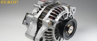
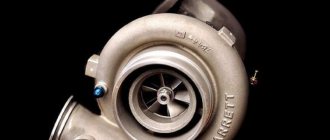
Operation of the hydraulic compensator
The operating principle is based on variable engine oil pressure. When the internal combustion engine is turned on, oil fills the internal part and, due to variable pressure, its plunger moves cyclically, preventing the formation of gaps in the valve drive and maintaining constant contact between the rocker arm and the camshaft cam.
Thus, hydraulic valve compensators
They significantly simplify engine maintenance and make the problem of precise valve adjustment during maintenance obsolete, but they require a more careful approach to the choice of oil and oil filter.
Design and principle of operation of compensators
Hydraulic compensator device
no different in complexity. It consists of a body, plunger, valve, spring, piston and retaining ring.
The principle of operation is also quite simple. When the camshaft cam is at the top point of movement, it is located with its rear part relative to the compensator. Because of this, the force is not transmitted to the compensator, which allows the spring to straighten and extend the plunger, due to which the gap disappears. Engine oil flows into the free space under the plunger through the valve. After filling the compensator, the oil pressure inside and outside it is compared and the valve closes.
When the cam turns its convex side towards the compensator, it begins to shift it downwards with its force. The oil-filled hydraulic compensator has enough rigidity to transmit the driving force of the camshaft to the timing valves without loss. During movement, some of the oil flows out of the compensator, resulting in the formation of a gap that existed at the beginning of the cycle. Then the cycle goes through again, and so on all the time the engine is running.
It should be noted that the operation of the hydraulic pusher
makes it possible to eliminate not only engine operating gaps formed as a result of the cyclic movement of its parts, but also gaps due to engine heating (heated metal expands) and increased gaps associated with wear of timing parts. Any increase in space for moving the compensator leads to the fact that it accepts more oil, still occupying the entire free volume.
Hydraulic compensators - design secrets
Let's get a little technical and look at how these devices automatically maintain the same clearance. Its main structural elements are:
The meaning of the operation of hydraulic valve compensators is to automatically compensate for gaps in the engine gas distribution mechanism that change under the influence of various factors, which is achieved by changing their length using springs and oil pressure.
As we mentioned above, hydraulic compensators are located between the camshaft (its cams) and the valves.
When the shaft cam is turned with its back side, a portion of oil enters the compensator from the ramp, which fills its cavity, and it seems to move up and down until it compensates for the gap between its body and the surrounding elements of the timing system.
When the shaft cam turns with its convex side towards the hydraulic compensator and presses on it, our today's hero is locked, and the oil, due to its incompressibility, turns it into a rigid element that presses on the valve, opening it.
When the compensator moves, part of the oil from its plunger pair exits through the existing internal gaps, and when returning to its original position, a fresh portion enters the hydraulic compensator from the ramp, filling its insides, and again the gaps are compensated.
Manufacturers of hydraulic compensators
INA hydraulic compensator kit
There is an established opinion that original (from the car manufacturer) consumables and parts, including hydraulic compensators, are better. Very often this happens, but there are a couple of nuances. First - original spare parts are usually more expensive
, sometimes several times than analogues. Secondly, some analogs are still better than the original.
Based on this, some in pursuit of savings and others for better quality, drivers can choose analog hydraulic compensators. Therefore, finally, we provide you with brief information and reviews about compensator manufacturers. So:
- INA hydraulic compensators
. INA's production facilities are located in Germany, in the city of Hirscheid. They are distinguished by excellent quality and a manufacturer's warranty, like any German equipment. Its hydraulic compensators have good reviews from drivers and are very common in Russia and the CIS countries. - FEBI hydraulic compensators
. Also a German company, but the warranty has a shorter period. In addition, the quality of parts from Germany differs; hydraulic compensators made under license in other countries may turn out to be defective, which will lead to engine overhaul. - SWAG hydraulic compensators
. Good parts are made in Germany, but sometimes you come across expansion joints that are much inferior to the original ones in terms of material quality. Probably as a result of counterfeit or defect. - Hydraulic compensators AE
. The European parts of this company have gained the reputation of being “not bad” due to their affordable price and satisfactory quality. At the same time, some note that these hydraulic compensators begin to knock after several thousand kilometers. - AJUSA hydraulic compensators
. Despite the attractive price, hydraulic compensators from this Spanish company rarely receive positive reviews. They are often criticized for poor workmanship, which quickly causes knocking and a short service life.
TKTG brakes with electro-hydraulic pushers TEG-25
Shoe brake with electromagnetic drive Read more: Maintenance, brake malfunctions
1.2 TKTG brakes with electro-hydraulic pushers TEG-25
Brakes with electrohydraulic pushers (Fig. 3) are free from the disadvantages inherent in electromagnets and are more reliable. The brake rod here is also pivotally connected to the large arm of a double lever mounted on the brake lever. Connected to the smaller lever arm is a rod attached with nuts to the brake lever. The brake is closed by the force of vertical springs. When the pusher rod moves upward, the lever rotates, compressing the springs, and the lever, together with the brake pad, moves away from the pulley until the stop reaches the base. Then the lever moves away from the block. The piston returns to its original position under the influence of a spring.
Figure 3 – TCTG brake
Device and principle of operation. The brake consists of the following main parts: electro-hydraulic pusher 1, mechanical part. The mechanical part consists of: support frame 10, brake spring assembly with protective casing 11 with braking torque table, spring adjusting bolt 3, upper lever 2, brake and auxiliary lever 5, adjusting rod 4, brake pads 6 with brake linings 7, adjusting block bolt 8, balancing adjusting bolt 9.
When the electro-hydraulic pusher is turned off, under the action of a compressed spring, the levers press the pads to the surface of the brake pulley. The rod of the electrohydraulic pusher is in the lower position. When the electro-hydraulic pusher is turned on, its piston pushes the rod up. The levers, freed from the action of the springs, diverge, releasing the pulley.
Electrohydraulic pushers (EGT) use the principle of creating hydraulic pressure under the piston, and the piston rod receives linear movement (Fig. 4).
Figure 4 — Electrohydraulic pushers of the TEG type:
1 - electric motor, 2 - housing, 3 - centrifugal pump, 4 - piston, 5 - cylinder, 6 - control plug, 7 - rod, 8 - rubber seal, 9 - filler plug, 10 - cover, 11 - clamp panel
The electro-hydraulic pusher consists of a squirrel-cage electric motor 1 and a housing 2 with a cover 10. A centrifugal pump 3 is mounted on the electric motor shaft. A piston 4 moves in the cylinder 5. The piston rod 7 is connected to the brake lever system. A rubber lip seal 8 is installed on the top cover, which prevents oil from escaping when the rod moves. The terminal panel 11 is used to connect the electric motor. Oil is poured into the electro-hydraulic pusher through the upper filler hole, closed by plug 9. Plug 6 is used to control the oil level. The joints between the body parts of the pusher are sealed with oil-resistant rubber rings.
The pusher is installed vertically with the rod up, the permissible deviation is ± 15°, provided that the load is directed along the axis of the rod.
Before installing electro-hydraulic tappets, you should check the insulation resistance of the stator winding relative to the motor housing and between the winding phases. The insulation test should be carried out with a megohmmeter with a voltage of 500 V. The insulation resistance in a cold state should be at least 20 MOhm. If the insulation resistance is lower, the engine must be dried at a temperature not exceeding 100 °C, having first removed it from the pusher. When hot, the insulation resistance must be at least 0.5 MOhm. Next, you need to check whether the pusher is completely filled with working fluid (transformer oil), and if necessary, add dry transformer oil. The oil must have electrical insulating properties - its breakdown voltage must be at least 20 kV/mm. The reason for the decrease in breakdown voltage can only be the entry of moisture or a conductive liquid into the oil. In this case, the oil must be changed after checking the insulation of the windings.
In comparison with brake electromagnets, electrohydraulic pushers have a number of advantages: their size and weight are smaller compared to electromagnets with similar operating parameters, and electricity consumption is also several times less. The magnitude of the pressure force of the hydraulic pusher does not depend on the position of the piston, while with an electromagnet the force changes sharply depending on the size of the air gap between the yoke and the armature. With an increase in external! load to the maximum thrust force of the pusher, the piston stops. In this case, there is no overload of the engine or mechanical damage to the elements of the pusher. Using an electro-hydraulic pusher, low drive speeds can be achieved.
The disadvantages of electrohydraulic pushers include a significant reduction in the force on the rod when the geometric axis of the pusher deviates from the vertical, a longer response time compared to an electromagnetic drive, and a change in its value depending on the ambient temperature.
The brake is adjusted in the following cases: when it does not slow down the mechanism when the engine is turned off or, conversely, sharply slows down the mechanism. When adjusting the brakes, follow the following sequence:
— establish the normal movement of the electromagnet armature;
— regulate the uniformity of the pads moving away from the pulley;
- check and set the length of the working spring.
The normal stroke of the electromagnet armature (Fig. 5,a) is set as follows.
Figure 5 — Adjustment of TKT and TKTG brakes:
a — armature stroke (at the TKT brake), b — rod stroke; 1 - rod, 2 - nut and locknut, 3 - auxiliary spring, 4 - bracket, 5 - main spring, 6 - adjusting nut, 7 - release nut, 8 - electromagnet body, 9 - electromagnet armature, 10 - brake coil, 11 — lock nut, 12 — adjusting bolt, 13 — levers, 14 — electric hydraulic pusher; A and B - adjacent rivets
Unlock nuts 2, 6 and 7 located on rod 1. Unscrew nut 7 until it presses the rod away from the rear lever 13, and the armature of the electromagnet 9 rests against the core of the electromagnet housing 8.
In this position, measure with a ruler, as shown in the figure, the distance from the outer end of the coil, electromagnet to the most distant outer surface of the armature in its lower part (For the MO-100B electromagnet, this distance is 25 mm, MO-200B - 48.5 mm). After this, nut 7 is screwed in such a way that it no longer rests against the lever, and the end of the rod presses the electromagnet armature.
In this position, the result of measuring H (Fig. 6,a) should be equal to the sum of two sizes: previously obtained with the armature closed and the value of the armature installation stroke (Rut), taken from the brake characteristics according to Table 1 (for the MO-100B electromagnet: 25 +11 = 36 mm; for electromagnet MO-200B: 48.5 + 14 = 62.5 mm). If the measurement results differ from the calculated ones, it is necessary to adjust the armature withdrawal using nut 2 (Fig. 5, a) located at the end of the rod. At the same time, the rod is kept from turning by the square shank at the end. When adjusting the armature stroke, you can measure the distance between adjacent adjacent rivets located on the armature and the magnet body (points A and B). The values of the armature stroke at the level of the geometric axis connecting these rivets are given in Table 1.
Table 1 — Setting values for adjusting brakes of types TKT and TKTG
| Parameter | Electromagnet | Electrohydro-pusher TEG-25 | ||
| MO-100B | MO-200B | MO-300B | ||
| Stroke of the anchor (at the level of the upper adjacent rivets, one is located on the anchor, the second on the yoke), mm | ||||
| — installation (Rus) | 5,5 | 7,0 | 9,0 | — |
| — maximum permissible (RPs) | 8,0 | 10,0 | 13,0 | — |
| Anchor stroke (at the level of the most distant point of the anchor), mm | ||||
| - installation (Ruth) | 11,0 | 14,0 | 18,0 | — |
| — maximum permissible (RPT) | 16,5 | 19,5 | 27,0 | — |
| Stroke of the rod (piston), mm | ||||
| — installation (Rush) | 2,0 | 2,5 | 3,0 | 22,0 |
| — maximum permissible (Рпш) | 3,0 | 3,8 | 4,4 | 32,0 |
To regulate the uniform withdrawal of the pads from the pulley, the electromagnet is again placed in the closed position by the release nut 7 of the rod. By rotating the adjusting screw 12 after loosening the locknut 11, achieve uniform distribution of the gap on both pads, which is checked with a feeler gauge or by rocking the levers. After this, the adjusting screw is fixed with locknut 11.
The last step in adjusting the brake is to check the length of the operating spring using a straight edge. The length of the spring is measured with the armature of the electromagnet open. The calculated braking torque that must be provided by the brake is given in the crane factory instructions for each mechanism. This moment must correspond to a certain installation length of the spring (with the brake pads locked), given in the instructions attached to the brake.
If the length of the spring differs from the installation one, adjust its length using nut 6, holding it with a key and rotating the rod in one direction or another by the square shank. If the length of the spring is not given, the brake can be adjusted according to the amount of run-out of the mechanisms under load, i.e. progress of movement of the working body of the mechanism after braking. Therefore, the brakes of the cargo and jib winches are adjusted with the maximum load on the hook at the corresponding reach. When ensuring the appropriate run-out, the crane should brake smoothly, without jerking.
After adjustment, all brake nuts are locked so that they do not loosen spontaneously.
Short-stroke brakes TKTG differ from TKT in that they use an electrohydraulic pusher 14 TEG or TGM instead of an MO electromagnet to release the brake pads (Fig. 5,b). The TKTG brake with the TEG or TGM electric hydraulic pusher is adjusted in the same sequence as the TKT. The difference is that instead of the stroke of the electromagnet, the stroke of the electrohydraulic pusher rod is adjusted with nuts 2, and the length of the spring is set with nut 6 on the spring rod. The uniform movement of the shoes from the pulley is ensured by screw 12. When adjusting the stroke of the rod, take into account that the rod 4 (Fig. 6, b) of the pusher should not reach the bottom stop when the shoes are closed.
Figure 6 — Schemes for measuring rod stroke when adjusting the brake:
a - with an electromagnet MO, b, e - with an electrohydraulic pusher; 1 — electromagnet, 2 — electrohydraulic pusher, 3 — brake rocker arm, 4.6 rods, 5 — rocker arm, 7 — lever with weight, 8 — vertical rod, 9 — adjusting thrust bolts, 10 — tension screw, 11 — connecting rod; 12 — frozen
It is necessary to ensure a minimum distance h (Fig. 6, b), which is obtained as the difference between the maximum distance H (Fig. 6, b), measured at the rod raised to failure, and the installation stroke specified in the instructions for the brake (Table 1).
Adjustment of the braking torque of brakes with electro-hydraulic pushers is ensured (see Fig. 3) by adjusting the installation length of the spring with nuts 3 and is selected from the table, as well as visually according to the plate located on the brake spring cover, taking into account the linear relationship between the magnitude of the braking torque and the installation length of the spring .
Adjustment of the working stroke of the electrohydraulic pusher rod is carried out in the following sequence:
— Loosen the adjusting bolt to an amount that does not interfere with the rotation of the pads and levers;
— Using a lever (crowbar), lift the upper lever 2 to its highest position;
— Lower the upper lever 2 by the amount indicated in the technical table and fix it in this position;
— Secure the levers with 5 rod nuts 4.
Adjustment of the gaps between the pulley and the pads is carried out with the adjusting bolt 8 turned out in the following sequence:
— Using a lever (crowbar), lift the upper lever 2 to its extreme position and fix it;
— Measure the total gap between the pulley and the middle of the pads using feeler gauges;
— Divide the gap into equal parts between each pad with adjusting bolt 8 and lock it.
Adjustment of the uniform retraction of the pads along the arc of contact with the pulley is carried out using adjusting bolts with lever 2 fixed in the uppermost position. Upon completion of the adjustment, the upper lever 2 must be unlocked, the brake must be brought into the inhibited state. Checking for guaranteed clearance between the pulley and the pads. This is done by several test lifts of the upper lever 2. If necessary, the adjustment is made again.
Shoe brake with electromagnetic drive Read more: Maintenance, brake malfunctions
Information about the operation of “Shoe brake with electromagnetic drive”
Section: Construction Number of characters with spaces: 43592 Number of tables: 5 Number of images: 8
Similar works
Repair of the drum-shoe brake of the T3 tram car. Semi-automatic welding of a flange in a carbon dioxide environment
34049
11
10
... small-sized parts, produce parts for artistic purposes. As an example, the use of semi-automatic welding in CO2 can be considered the welding of a part such as a flange, which is also part of the structure of tram cars. 4 Repair of drum-and-block brakes of the T3 car 1. Structure and purpose of the drum-and-block brakes of the T3 car Structure ...
Car brake system
54587
10
1
... efficiency (minimum braking distance) while maintaining vehicle stability and controllability. Therefore, in this thesis project it is proposed to use ABS in the braking system of a multi-purpose army vehicle with a pneumatic drive. The main task of ABS is to maintain the relative slip of the wheels within narrow limits during braking. In this case,…
Development of an electric elevator drive
58511
2
27
...more than 60 V DC. The position of these switches must be indicated by appropriate symbols or inscriptions: “On”; "Off." 3. Selection of the type of current and type of electric drive The elevator electric drive must satisfy the following requirements: a) the short circuit of the current-carrying parts of the electric brake drive device (electromagnet, etc.) to the housing must not cause spontaneous ...
Cheat sheets for the life safety exam (Bryansk)
481815
2
0
... commissions with the participation of a representative of state supervision and they are issued certificates. Workers increase their level of knowledge on occupational safety through advanced training courses and passing exams. 136. Types of instruction, registration of instruction. Briefing of workers is divided into: 1. introductory 2. primary at the workplace 3. repeated 4. unscheduled 5. targeted All...
Signs and causes of failure
The main reasons for the failure of the hydraulic compensator (HC) are contamination of the oil channels
engine and
wear of the working surfaces
of the check valve and plunger pair.
The main sign that the hydraulic valve compensators have failed is the characteristic knocking sound of the valves when the internal combustion engine is running, including at idle. This problem can be caused by a number of reasons, including:
- the presence of air in the above-plunger cavity of the compensator, which happens when the oil level in the crankcase is incorrect or when the machine is parked for a long time at a large slope;
- clogging of the compensator with sludge from low-quality engine oil or not replaced on time;
- wear of compensator mechanisms.
7 Reasons for knocking of hydraulic compensators on a hot engine
- The oil has not been changed for a long time or low-quality oil was used.
- The channels through which oil is supplied to the hydraulic compensator are clogged.
- The oil filter is clogged and the oil does not reach the hydraulics at the required pressure.
- Problems with the oil pump.
- Incorrect oil level (low or high).
- Increasing the seating area of the hydraulic compensator.
- Problem with the mechanics and hydraulics of the hydraulic valve compensator.
Basic faults
The use of low-quality motor oil and (or) its contamination (for example, due to untimely replacement of the lubrication system filter and oil) can lead to the following consequences:
- an increase in the gap in the plunger pair, which causes increased oil leakage from the cavity under the plunger. The hydraulic compensator does not have time to select gaps in the timing belt, and characteristic knocking sounds appear;
- wear or clogging of the ball valve, causing it to not close tightly and, accordingly, increasing oil leaks from the cavity under the plunger;
- jamming of the plunger pair, which completely disables the hydraulic compensator. Shock loads occur in the timing belt, leading to increased wear of parts and premature failure.
In some cases, valve clogging can be eliminated by flushing the engine with special oil. All other faults, as a rule, require replacement of hydraulic compensators.
Trouble-shooting
In some cases, troubleshoot hydraulic compensators
possible at home.
Flushing
, as a rule, helps get rid of knocking.
cleaning of the oil channels
is also required .
First you need to check the engine oil level in the engine and, if necessary, bring it up to normal. To get rid of air in the compensator, you need to start the engine and slowly accelerate it ten times. The problem can be considered solved if the abnormal sound of the motor disappears.
What are hydraulic compensators
We'll have to delve a little into the jungle of engine design. At the top of the engine there is a cylinder head, inside which a camshaft rotates (possibly more than one). In appearance, the camshaft looks like a regular axle, which has cams. What can I tell you? I even still have a photo from the capital.
The red circle just highlights the camshaft cam and the hydraulic compensator underneath it. The cam must press on the valve to open it, but the length of the valve is not constant - a cold valve is shorter, a hot valve is longer. See what the valve looks like so you can understand what we are talking about.
So here it is. In order for the valve to always close at the same stroke time, some kind of layer is necessary between the camshaft cam and the valve stem. Previously, they resorted to using adjusting pennies, that is, they placed a special calibrated pancake on the valve stem, which made it possible to precisely close the valve at the right time when the engine was warm. However, if the valve is worn out, or the nickel is selected incorrectly, when closing the valve, the cam will not fit tightly against the adjusting washer and, as a result, the valve will hit its seat. This phenomenon is called "Valve knocking". This could actually be the sound of a valve hitting the head or a camshaft lobe hitting a washer. As wear progressed, an operation to regulate the valves was required, that is, replacing the washers with thicker ones. This operation is quite tedious, and the most important thing is that it had to be repeated often. In addition, we can say that adjusting the valves with washers is not quite perfect, because the valve is shorter when cold, the valve is longer when hot, and it is impossible to adjust the valve for both modes of engine operation. This is where hydraulic compensators were invented. Understanding the principle of their operation is quite simple: imagine an ordinary hand pump. If you plug the outlet hole of this pump, you will be able to raise the pump handle, but you will not be able to lower it, even if you hang on the pump. The hydraulic compensator is built on this principle. In a relaxed state, engine oil is supplied to it, which fills its cavity, but it takes a long time for the hydraulic compensator to release oil - it will take several hours for it to go down a little. Like a hand pump in general.
Thus, a hydraulic compensator is a thing that is very easy to fill with oil but very difficult to empty. The use of hydraulic compensators allows you to forget about adjusting valves throughout the entire life of the engine.
Why are hydraulic valve compensators needed?
What does a hydraulic compensator look like?
As the engine operates, its parts heat up and expand. To prevent them from being damaged, designers provide special thermal gaps that disappear when the internal combustion engine warms up. However, engine elements are made of different materials, characterized by different coefficients of thermal expansion. Consequently, the parts will expand to varying degrees, which may disrupt the coherence of the entire valve system. In order to smooth out this difference, hydraulic compensators were developed.
The main task of hydraulic valve compensators is to absorb gaps between the valves and the surfaces of the camshaft cams. This ensures accurate valve opening, reduces the noise level generated during engine operation, and also has a positive effect on fuel consumption. In addition, the use of hydraulic compensators helps reduce the shock load on the valves, thereby increasing the duration of their use.
Before the invention of hydraulic lifters, valve adjustment was done manually. This was a rather labor-intensive procedure that required regular execution. It was necessary to set the gaps with high precision: 0.15-0.25 mm for the intake valves and 0.2-0.35 mm for the exhaust valves.
If you do not take care of adjusting the valves, the engine will not operate efficiently:
- if there is no gap at all, then the valves simply will not close completely. As a result, combustion of the working mixture can occur in the intake manifold, which leads to a decrease in engine power and difficulty starting. The valve plates and seats gradually burn out and collapse;
- if the gap is excessively large, then the piston fists regularly hit the valves, which is accompanied by a characteristic metallic sound. Due to such impacts, valves, camshafts and other timing elements wear out prematurely and become unusable. The valve opening range decreases, the balance of the fuel-air mixture entering the cylinders is disrupted, and their ventilation deteriorates. As a result: power decreases, exhaust toxicity increases.
Article on the topic: New driver's license - the number of categories has tripled
In order to make the operation of the valve system smoother and more stable, elements such as hydraulic compensators are added to its design. These are elements with a movable structure, the length of which changes in proportion to the change in the thermal gap.
Hydraulic lifters are knocking
This phenomenon happens and there are five reasons for it:
- Low oil pressure, as a result of which the hydraulic compensator cannot be filled with oil to 100 percent.
- Low oil level in the engine, as a result of which the engine head experiences oil starvation, and less oil gets into the compensators than necessary.
- High wear of the hydraulic compensator, which led to its leakage.
- Coking of the compensators, which in turn leads to leakage of the part, and it is easily pressed through.
- Coking of hydraulic compensators, which leads to jamming of the compensator in a certain position.
Hydraulic compensators can knock only because they are easy to push through or they have lost the ability to be pressed. I listed the reasons for easy squeezing and jamming above.
Cleaning or decarbonizing the hydraulic compensator
Some hydraulic compensators have a collapsible design, and by disassembling it, you can actually clean the deposits that prevent it from working properly. This operation is performed entirely at your own peril and risk and no one can guarantee that the cleaned compensator will be operational. Moreover, no one will take on this work in a car service center.
I myself did this kind of work on my car, which helped me postpone replacing the hydraulic compensators for half a year.
To clean the hydraulic compensator we will need a coarse cotton cloth, pliers, a small gas wrench and a strong solvent. And of course all the tools for removing the engine head and camshaft. When removing the head, you will most likely have to remove the timing belt, which will then need to be set back to its markings. Also be careful when tightening the camshaft beds - it is best to pull with a torque wrench and strictly under the correct force. The valve cover must also be pulled with a torque wrench or with ideally equal forces. If the valve cover is not tightened evenly, oil will leak or leak from under the valve cover gasket.
A little history
Hydraulic compensators have replaced less efficient mechanical regulators of gas distribution mechanisms. As a rule, a regular engine valve, say on a classic VAZ 2105 - 2107 engine, does not have a hydraulic compensator, so it often had to be adjusted, on average after 10,000 kilometers. Valve adjustment on VAZ 2105 - 2107 was done manually, that is, you had to remove the valve cover and set the gaps using a special feeler gauge, which varied in thickness, which means you could choose it for your mileage.
If adjustments are not made, the car engine begins to make noise, dynamic characteristics decrease, and fuel consumption increases. After 40 - 50,000 kilometers, the valves generally should have been changed. That is, mechanical valve adjustment, to put it mildly, has outlived its usefulness, it was necessary to do something, to improve the design, so to speak.
So on front-wheel drive VAZ engines, they began to install mechanical pushers in front of the valve. To exaggerate, a large “cap” was simply put on top of the valve; it has a larger diameter (than the old design), and therefore wear was much reduced, because it is much more difficult to wear out a larger diameter than a small one. But adjustment still remains, of course not every 10,000 kilometers, much less often, but it is still recommended to do it. This usually happened by placing repair “washers” of increased height. Mechanical adjustments are quite effective and are still used by some manufacturers; adjustment with washers is recommended no earlier than 40 - 50,000 kilometers (if we talk about our VAZs); on some foreign cars the pushers last even longer. The big advantages are the simplicity of the design, unpretentiousness (semi-synthetic oils can be poured), as well as the relative cheapness of the design. The disadvantages can be noted that when the “washers” on top were worn out, the engine began to work noisier, the dynamic characteristics dropped and the consumption increased. What was needed was a design that automatically adjusted the gap.
And now, mechanical valve adjustment has been replaced by a completely new technology. Everything is simple here - now you don’t need to adjust the valves manually, hydraulic compensators will do everything for you. They themselves will set the required engine valve clearance, due to which the engine life is increased, power is increased, fuel consumption is reduced, and the mechanism runs for quite a long time - 120 - 150,000 kilometers (with proper maintenance). In general, a step forward.
Advantages and disadvantages of a mechanical pusher
Let us briefly recall how the gas distribution mechanism (GRM) of a car engine works. When the camshaft rotates, it “impinges” (to be more precise, the protruding part, which is called the cam) onto the surface of the pusher resting on the valve stem. At this moment the opening of the latter occurs.
When the cam no longer "contacts" the tappet, the return spring closes the valve. It would seem that everything is simple. But, as the engine warms up, all metal structural elements expand. Everyone knows this from school physics courses. In engines equipped with conventional mechanical pushers, a certain gap is initially provided to compensate for the thermal expansion of the elements.
As it warms up, it decreases, and the engine begins to confidently produce all the characteristics declared by the manufacturer. If this had not been done, then in a warm engine, the extended timing elements would, at best, experience increased loads (which would lead to their premature wear), at worst, they would simply jam.
The undoubted advantages of conventional pushers include:
- Simplicity of design, and, as a result, low cost.
- “Undemanding” to the quality of the oil (carbon deposits and deposits do not affect their operation) and the frequency of its replacement (usually every 15,000 km).
The most important disadvantage of the simple and fairly reliable design of a mechanical pusher is the need for periodic manual adjustment of the thermal gap (this procedure does not have to be performed very often in modern vehicles - every 80,000÷100,000 km).
How do they do it? First, the gap size is measured using special probes. Then select an adjusting washer (if there is one, as for example in many engines of the family of front-wheel drive VAZ cars) of the required thickness. But it is not always possible to do this. Many foreign cars have to replace the pusher with a new one, since the adjusting washer is simply not provided for in their design.
Adjustment is carried out only on a cold engine. The current thermal gap is determined by special metal flat probes of different thicknesses. To change the clearance on the rocker arms there is a special adjusting screw that is turned. In systems with pushers or shims, adjustment occurs by selecting parts of the required thickness.
Adjusting valves for a rocker mechanism
Let's look at the step-by-step process of adjusting valves for engines with pushers (cups) or washers:
- Remove the engine valve cover.
- Rotate the crankshaft so that the piston of the 1st cylinder is at TDC. If it is difficult to do this by following the marks, then you can unscrew the spark plug and insert a screwdriver into the well. Its maximum upward movement will show the dead center.
- Using a set of feeler gauges, measure the valve clearance under the cams that do not push the tappets. The feeler gauge should move tightly, but not too freely. Write down the valve number and clearance.
- Rotate the crankshaft one revolution (360°) so that the piston of the 4th cylinder is at TDC. Measure the gap under the remaining valves. Record the data.
- Check which valves have gaps that are out of tolerance. If there are any, then select the pushers of the required thickness, remove the camshafts and install new cups. This completes the procedure.
Read more: Operating a car in winter - 7 valuable tips
It is recommended to check the gap every 50-80 thousand kilometers. Standard clearances can be found in your vehicle repair manual.
A properly configured and adjusted gas distribution mechanism will ensure smooth and smooth operation of the internal combustion engine. This will also have a positive effect on engine life and driver comfort.
What are the types of hydraulic compensators?
These devices are widely used in timing systems. However, their analogues are also used in chain tensioning, the so-called “ timing chain ”. For this period of time, only 4 designs are used.
- Hydraulic pusher. Often used on modern cars to adjust the gap between the valve and the camshaft
- Hydro support
- Hydraulic support for installation in levers and rocker arms. Mainly used on old timing mechanisms
- Roller hydraulic pusher
All 4 types can be found on various designs, although “hydraulic mounts” were often used earlier in engines. Now everything is more. It’s a little clear about the types, now let’s learn more about how they work.
Operating principle of hydraulic compensator
First, I want to look at the components of the hydraulic pusher:
- Camshaft cam
- Groove in the body of the hydraulic compensator
- Plunger bushing
- Plunger
- Plunger Valve Spring
- Timing spring
- Gap between hydraulic compensator and camshaft cam
- Ball (valve)
- Oil channel in the body of the hydraulic compensator
- Oil channel in the cylinder head
- Plunger spring
- Timing valve
The hydraulic compensator is like an intermediate link between the valve and the camshaft of the gas distribution mechanism. When the shaft cam (1) does not press on the hydraulic compensator, the valve (12) is in the closed state under the influence of the spring (6).
The plunger spring (11) presses on the plunger pair (3 and 4), due to which the hydraulic compensator body moves towards the shaft until it rests against it, thereby dividing the gap to a minimum.
The pressure inside the plunger is produced using oil pressure, from the engine it moves through channel (10) and then into the channel of the compensator itself (9). Then it goes inside through the groove (2), where it bends the valve (8) and passes through creating pressure.
The camshaft cam then moves down, creating pressure on the hydraulic compensator. The oil that has entered the plunger pair creates pressure on the valve (8), actually packing it. As you and I know, oil practically does not compress, therefore, after locking, the compensator acts as a rigid element that presses on the timing valve, opening it.
It is worth noting that this is a highly efficient device, the oil is squeezed out a little from the plunger pair before the ball-shaped valve (8) locks it inside. Thus, a small gap may form, which will be removed during the next pumping of oil through channels (9 and 10) and the hydraulic compensator will become rigid again.
Thus, despite the engine temperature and thermal expansion, the maximum possible gap will always be set. This mechanism does not need to be adjusted throughout its service life, even despite its exhaustion, because it is always effectively “pressed” to the camshaft.
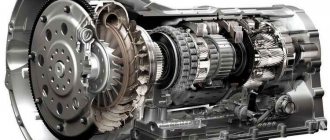
Drive device
The camshaft and timing drive are responsible for the correct and timely operation of the valve mechanism. The design and number of camshafts for each engine type are selected individually. The part is a shaft on which cams of a certain shape are made. As they rotate, they put pressure on the pushers, hydraulic compensators or rocker arms and open the valves. The type of circuit depends on the specific engine.
Gas distribution mechanism
The camshaft is located directly in the cylinder head. The drive to it comes from the crankshaft. It can be a chain, belt or gear drive. The most reliable is the chain one, but it requires additional design solutions. For example, a damper to dampen chain vibration and a tensioner. The camshaft rotation speed is two times lower than the crankshaft rotation speed. This ensures coordination of their work.
Read more: The process of replacing the fuel filter on a Sorento KA photo and video
The number of camshafts depends on the number of valves. There are two main schemes:
- SOHC (single shaft);
- DOHC (double shaft).
If there are only two valves, one camshaft is sufficient. Rotating, it ensures alternate opening of the intake and exhaust valves. The most common four-valve engines have two camshafts. One ensures the operation of the intake valves, and the other exhaust valves. Engines with V-shaped cylinders have four camshafts. Two on each side.
The camshaft lobes do not push the valve stem directly. There are several types of "intermediaries":
- roller levers (rocker arm);
- mechanical pushers (cups);
- hydraulic pushers.
Roller levers are a more preferred design. The hydraulic pusher is pressed by so-called rocker arms, which swing on plug-in axles. To reduce friction, the lever has a roller that contacts directly with the cam.
Another scheme uses hydraulic pushers (lash compensators), which are located directly on the rod. Hydraulic compensators automatically adjust the thermal gap and ensure soft and less noisy operation of the mechanism. This small part consists of a cylinder with a piston and spring, oil passages and a check valve.
Removing the valve cup with a magnet
Mechanical pushers (cups) are a sleeve closed on one side. They are installed in the cylinder head housing and directly transmit force to the valve stem. Their main disadvantages are the need to periodically adjust the gaps and knocking when operating on a cold engine.
Pros and cons of a hydraulic compensator
There are many positive aspects to this mechanism:
- It is completely maintenance-free and works automatically
- Increased timing system resource
- Maximum pressure, which gives good traction
- Minimum fuel consumption
- The engine always runs quietly
Well, despite all the advanced design, there are also a fairly large number of disadvantages.
- Since all work is based on oil pressure, you need to fill in only high-quality lubricants. Synthetic is desirable
- Need to change oil more often
- The design is more complex
- Expensive repairs
- Over time, they can become clogged, which impairs engine performance (consumption and traction), and the timing belt begins to make noise.
The biggest disadvantages are that the design is expensive and complex, and is VERY demanding on the quality of the oil. If you pour “don’t understand what” they will very quickly fail and require replacement. For example, conventional mechanical pushers are much simpler and less demanding on the quality of lubrication.
Why do hydraulic compensators knock?
To begin with, I would like to note that if the compensators are knocking, this indicates that they are not working correctly, most likely they are out of order, or something is wrong with the engine lubrication.
Actually, the main reason lies in the quality and level of the oil, although there are a lot of mechanical faults.
- Not enough oil. This also happens, it is not pumped effectively into the channels and therefore is not pumped inside the plunger pair, that is, the required pressure is not created inside
- The channels in the cylinder head or the hydraulic compensator itself are clogged. This happens due to untimely oil changes, it burns and deposits form on the walls, which clog the channels; the oil cannot effectively pass into the compensator.
- The plunger pair has failed, often it simply jams
- The plunger ball valve has failed
- Carbon deposits on the outside of the plunger body. He physically does not allow him to rise and compensate for the gaps
Of course, sometimes they knock because there is carbon deposits in the system, then you just need to remove them and wash them, and their performance may be restored. BUT with high mileage, they break (depletion appears) and require replacement.
I want to repeat again - you need to understand that the operation of the hydraulic compensator depends on the quality of the oil and its timely replacement. You need to pour only high-quality synthetics and my advice to you is to change the lubricant a little more often than prescribed, for example, after 15,000 km, change after 10 - 12,000 km. They will last longer.
Now let’s watch a short detailed video.
I’ll end here, sincerely yours, AUTOBLOGGER.
( 28 votes, average: 4.61 out of 5)
Similar news
Running in a new car - is it necessary? Or you can immediately “fever.”
How an oil filter works and is designed. Let's look at an ordinary car.
Additives for engine oil, steering rack and gearbox. Ch.
How often to adjust valves on Rio
The factory repair instructions for Kio Rio state that the clearances should be checked every 90,000 km or if extraneous noise or other problems with the engine occur. But we must understand that the Koreans wrote these regulations for engines running on gasoline. This is not relevant for cars with HBO. According to statistics, when running on gasoline, the valve clearances can be left untouched throughout the entire life of the engine, until a major overhaul. It's a different matter when running on gas. Here the mileage before adjustment is from 40,000 to 90,000 km. It depends on the correct settings of the gas control unit, driving style and other factors.
If your car has an LPG, check the gaps every 45,000 km.
Non-contact infrared thermometer temperature. Accurate. Price 3,979 rub.
Buy