The engine structure is directly connected to the engine lubrication system. Unfortunately, it is not possible to permanently eliminate friction. Measures aimed at combating have one goal, to reduce the impact to minimize negative consequences. Thus, each engine is equipped with an assortment of comprehensive protection called an engine lubrication system.
Self-propelled crew with the first engine installed:
The role of lubrication in a power engine
In the manufacture of a power plant, complex technical solutions are used that help make the surface of parts and mechanisms durable. However, interactions between parts are inevitable, a by-product of friction causing increased wear. The lubrication mechanism is the only simple, accessible and reliable method of combating, a replacement for which has not yet been found.
The purpose of the engine lubrication system, maintaining the performance and functionality of the motor, the detailed tasks are as follows:
Covers vulnerable surfaces with a thin, uniform protective layer of oil;
- Eliminates and removes excess heat;
- Cleans the surface of the part, washes away mechanical particles and dirt;
- Protects the part and prevents oxidation;
- Improves connection and forms a bond between parts;
- Performs the function of controlling mechanisms.
The above functions are possible due to the constant circulation of oil through the channels inside the unit. Continuous movement guarantees that the oil will be cleaned and cooled in time. Corrosion protection is provided by the composition of the lubricant; the inclusion of additives and additives in the liquid helps the oil stay on the surface, blocking the access of air and eliminating the causes of oxidation. Due to the role of the working fluid, the motor automatically regulates and configures individual components and mechanisms. For example, hydraulic valve compensators automatically adjust thermal clearances.
Types of systems: engine lubrication
Due to the fact that the design of the engine lubrication system provides for various methods of supplying oil to points that urgently need lubrication, three methods are distinguished:
Supply of working fluid by spraying onto the surface
The method is simple, but it has a number of disadvantages. The principle is based on scooping up oil with special recesses on the connecting rod heads. Having captured the liquid, centrifugal force sprays the oil along the inner surface of the engine, lubricating the parts. The main disadvantage of the method is that the quality of the work performed is directly related to the amount of oil in the engine crankcase and the road conditions under which the car is operated. Tilt, lack of oil, crankshaft speed, this affects the process. Often the power unit quickly wears out and becomes unusable due to lubrication and lack of working fluid.
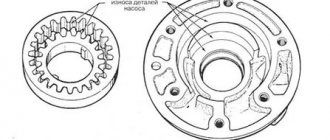
Lubrication system oil pump repair
The oil pump must be repaired when the oil pressure in the engine lubrication system is below the values specified in the operating manual.
First you need to check the condition of the pump pressure relief valve. To do this, you need to remove the pressure reducing valve assembly and check the condition of its parts.
Valve parts, cleaned of oil deposits and washed in kerosene, must move freely in the pressure reducing valve body. The length of the valve springs must correspond to the values set by the manufacturer at a certain load. If during testing there is a deviation from the specified control values, then it is necessary to disassemble the pump.
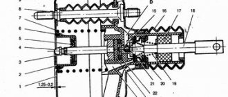
It is recommended to disassemble the oil pump in the following order:
- wash the pump in a degreasing solution, secure it in a vice and press out the pins;
- unscrew the three bolts securing the lower section housing (for a two-section pump), remove the bolts, remove the lower section housing with the gasket, remove the driven gear of the lower section and remove the axle from the oil pump housing using a puller, lightly tapping it with a wooden hammer;
- unscrew the plug and remove the pressure reducing valve (spring and plunger);
- press the centering coupling and shaft assembly with two drive gears and an intermediate cover on a bench press;
- remove the gasket of the upper pump housing, the driven gear of the upper section and press out the axle;
- secure the pump shaft in a vice with soft pads and remove the drive gear of the lower section from the shaft, then remove the first key from the groove of the pump shaft, remove the retaining ring using a screwdriver and the intermediate cover;
- Press the drive gear using a bench press and remove the second key from the oil pump shaft groove.
It will be useful to identify the causes of a Peugeot 308 malfunction while idling.
The parts of the disassembled oil pump need to be washed and their geometric dimensions checked.
The diameters of the holes in the oil pump housing for the pump drive shaft must correspond to the permissible values. If the hole diameter increases beyond the permissible values, the housing must be replaced or the holes repaired. The depth of the cavities for the gears of the upper section must correspond to the permissible values. If the depth increases beyond the permissible value, the housing must be replaced or repaired. The diameters of the cavities for gears in the housing and cover also need to be checked for compliance with acceptable values. If the diameter increases beyond the permissible value, the body or bottom cover must be replaced or repaired.
The following dimensions also require verification:
- diameters of the holes for the axes of the driven gears in the housing and in the bottom cover of the pump;
- diameters of the driven gear axes;
- depth of cavities for gears in the bottom cover of the pump;
- the diameter of the oil pump drive shaft and the width of the shaft keyway.
One-sided wear of the axles is unacceptable. Worn axles should be pressed out and replaced with new ones.
The split surfaces of the pump intermediate cover in contact with the ends of the gears must be flat and parallel. The parallelism tolerance should not exceed 0.03 mm on a 50 mm day. The flatness tolerance of the cover surfaces or development should not exceed 0.04 mm. It is allowed to grind the cover no more than 0.15 mm on each side. The surface of the lower section of the pump housing in contact with the ends of the gears must be flat. The flatness tolerance of the cover surface or groove corresponds to 0.04 mm, the parallelism tolerance is no more than 100 mm.
To monitor tightness and detect leaks through invisible cracks, it is recommended to check the oil pump housing, intermediate cover and lower section housing by supplying water under a pressure of 0.4 MPa.
The pump is assembled in the reverse order of disassembly. All paper gaskets should be replaced with new ones when assembling the pump. The gaskets are lubricated with a thin layer of UN-25 sealant or another product that meets the manufacturer’s requirements.
When installing the pump drive shaft, clearances must be provided between the shaft and the housing bore and between the axle and the gear bore. When assembling the pump, pay special attention to the following. The driven gear axis must be pressed into the housing with an interference fit of 0.032... 0.077 mm. The centering coupling on the drive shaft must be seated with an interference fit of 0.004... 0.048 mm. If the coupling on the shaft wobbles (there is a gap), it should be replaced. When pressing on the centering coupling, it is necessary to maintain the size from the end of the pump to the upper edge of the coupling in accordance with the manufacturer's requirements.
Use a feeler gauge and ruler to check the oil pump clearances:
- the gap between the gear teeth and the housing walls is 0.100...0.175 mm (the maximum permissible gap is 0.25 mm);
- clearance in the meshing of gear teeth - 0.14...0.24 mm (maximum permissible clearance 0.25 mm);
- the gap between the ends of the gears and the plane of the upper section housing with a gasket installed with a thickness of 0.17 mm is 0.120...0.195 mm (the maximum permissible gap is 0.20 mm);
- the gap between the ends of the gears and the plane of the lower section housing is 0.135 ... 0.188 mm (maximum permissible gap 0.20 mm).
Rice. Checking the oil pump clearances using a feeler gauge and ruler: a - checking the clearance between the gear teeth and the housing walls; b - checking the gap in the meshing of gear teeth; c - checking the gap between the ends of the gears and the plane of the housing; d - checking the gap between the ends of the gears and the plane of the bottom cover body
The pump drive shaft installed in the pump housing, after tightening all the bolts, should be easy to turn by hand without jamming. If there is jamming, it is allowed to add one gasket with a thickness of no more than 0.06 mm. It is recommended to test the assembled pump on a special stand. The pump oil supply values must be within the values specified by the manufacturer.
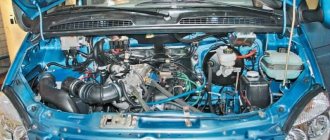
Engine lubrication system design
To better understand how the system works, let’s figure out what elements and parts are used to lubricate the engine. Today, power plants operating by combustion of a combustible mixture are equipped with the following parts:
- Oil pan The crankcase is the base body part of the power plant, in the cavity of which the crankshaft is located. The lower part of the crankcase is covered with a sump, which is attached to the structure with bolts. The function of the pan is to store and cool the lubricant; in addition, special partitions are installed inside the product to prevent oil fluctuations and reduce the formation of foam. A gasket is installed between the pan and the crankcase, the purpose of which is to prevent oil leakage.
Lubrication Methods
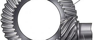
The first motors were lubricated by splashing. A similar lubricant was used while the motors were relatively low-speed and lightly loaded. Later, they began to use the supply of lubricant to the friction zone under pressure (hydrodynamic lubrication). In this case, a lubricating film in the form of an oil wedge is formed in the contact zone, due to which dry friction is replaced by liquid friction.
However, only cylindrical surfaces can be lubricated in this way: main and connecting rod journals, camshaft supports, piston pins, turbine bearings. The remaining parts (timing chain, valves, rocker arms, pushers) are lubricated by splashing or watering. This type of scheme is called combined and is used most often today. So, the basic schemes for lubrication of engine elements:
- splashing;
- under pressure;
- combined.
Attention! A sudden drop in pressure during a pressure lubrication scheme can lead to jamming of parts of the crank mechanism.
The lubrication system of a two-stroke engine stands apart. It comes in two types:
- Pre-mix lubricating oil and gasoline in a ratio of 1:20 - 1:50. Lubrication is achieved by oil mist.
- Separate. Oil is injected from the tank by a plunger pump into the inlet pipe.
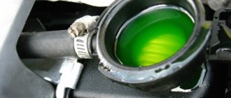
To lubricate two-stroke units, special two-stroke oil is used. In order not to be confused with the usual one, it is given an unusual color (red, blue, green).
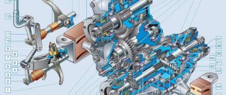
Operation of the lubrication mechanism
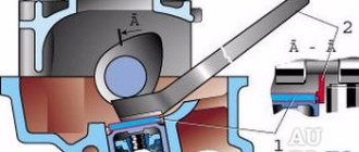
The lubrication scheme for the mechanisms and components of the unit is as follows: when starting the power plant, liquid is pumped into the line using a pump. After which the oil is cleaned by passing through the filter element. Next, the fluid flows to the crankshaft bearings, lubricates the connecting rod and main bearings and moves further to the camshaft bearings. Using nozzles or special holes, liquid enters the cylinder through the connecting rod supports and is sprayed onto the working surface of the liner. Excess oil is removed from the cylinder surface using an oil scraper ring. The remaining mechanisms are lubricated by splashing. After completing the function, the working fluid again enters the oil pan, where it cools and repeats the cycle again.
Important! Diesel units have a different operating principle, so the motors are subjected to high temperature loads, and the pistons of the units become very hot. For this purpose, some engine designs are equipped with a nozzle that sprays lubricant onto the bottom of the piston.
Engine lubrication system diagram:
Cylinder liners require continuous and sufficient lubrication to reduce friction losses and wear of the piston rings and cylinder bore. The oil film seals the gap between the rings and the bushing and also acts as a corrosion inhibitor. Some oil enters the groove, reducing wear on the groove and ring surfaces, and allowing the ring to move freely in the groove as it follows the bushing profile as the piston moves.
The internal cylinder cavity of powerful crosshead diesel engines is completely isolated from the crankcase, and each liner has its own separate lubrication system, providing a dosed supply of lubricating oil. For engines running on heavy fuel, special cylinder oils are used. They have a high alkalinity (usually a neutralization number of 70) to neutralize the acids produced by the combustion of sulfur present in the fuel. Cylinder oil must maintain viscosity at high temperatures, be resistant to oxidation and coking, atomize well and be retained as a film on working surfaces. To protect against cylinder bore scuffing and reduce ring wear due to carbon formation, high thermal-oxidative stability of oils is required.
During operation, alkaline additives are used and the oil “aging” occurs. Therefore, reuse of used oil is not permitted.
Oil is supplied to the cylinder through several drillings in the sleeve (usually 6-8), located evenly around the circumference at certain height positions, in accordance with the positions of the piston. Oil injection is carried out by pressure pulses from mechanical lubricators driven by a camshaft, which can be individually adjusted to a given oil flow rate. The connection of oil pumps with the main engine regulator allows, simultaneously with a change in fuel supply (change in engine power), to change the amount of lubricant supplied to the cylinders. Lubricators are connected to the bushing lubrication holes through non-return valves, which prevent hot gases from escaping into the lubrication system.
An ideal lubricator should be adjusted to inject oil precisely between the piston rings as they pass the lubrication hole. In practice, due to backlash and elasticity of the system, it is not possible to achieve such accuracy, as a result of which oil is simply injected into the cylinder cavity under the rings during the upward stroke of the piston. An accumulator connected to each lubricator is capable of storing more than a single supply of oil, delaying oil injection until the cylinder pressure has dropped to the non-return valve operating limit. As a result, oil is not supplied to the area of hot gases with high pressure at all.
The vertical location of lubrication points depends on the design of the machine. They must be kept away from the combustion chamber, with its high temperatures and pressures, and away from windows through which excess lubricating oil may escape. The distribution of feed around the circumference of the bushing is carried out by oil drainage grooves located at an angle, along which the oil spreads under the influence of gravity, reducing the effect of scraping it off by the rings. The distribution of oil along the length of the cylinder is carried out by the rings during their reciprocating motion.
Mechanical lubricators must be turned on before starting the engine to ensure that the rubbing surfaces are prepared for movement and the oil supply begins at the very first revolutions.
The oil supply should be temporarily increased during the running-in periods after replacing cylinder liners or piston rings. On engines with counter-moving pistons, each bushing is equipped with two sets of lubrication holes, each of which provides lubrication to one piston. Due to higher operating temperatures, the lubricating oil supply to the upper (exhaust) piston must be higher.
The same cylinder lubricators can be installed in trunk-type engines as in crosshead engines. However, due to smaller cylinder diameters, fewer lubrication points are typically used around the circumference of the bushing. Since most of these engines are four-stroke, they do not have windows in the cylinder liner through which oil can be carried away. The average temperature of the cylinder is reduced due to cooling during the exhaust-suction strokes. Therefore, the lubrication system for such diesel engines is subject to less stringent requirements than for two-stroke ones. Cylinder lubrication is often accomplished by simply spraying oil from the crankcase, which falls in the form of drops or mist onto the exposed lower surface of the cylinder bore. This can even cause an excess amount of lubricating oil, which at high speeds is removed by the oil scraper rings and returned back to the crankcase. Waste oil from the cylinder also flows into the crankcase and is mixed with the total volume circulating in the cylinder and bearing lubrication system. Thus, the lubricating oil must be a single oil suitable for lubrication of both cylinders and bearings. For engines with trunk pistons running on heavy fuels, it is necessary to use alkaline additives, increasing the neutralization number to 30-40. The active substances of these additives are consumed upon contact with combustion products, so constant quality control of crankcase oil is necessary. Stable lubrication characteristics are ensured by constantly replenishing the system with fresh oil.
Engine operation in conditions of insufficient cylinder lubrication leads to increased wear of cylinder liners and piston rings. When using heavy fuels, their corrosion increases. Deterioration of the piston ring seal causes the breakthrough of hot gases into the space under the piston, leading to overheating of the movement parts, rapid wear of the rubbing surfaces and possible jamming. In trunk engines there is also a risk of explosion in the crankcase. Excessive lubrication can cause increased carbon formation, sticking of piston rings with subsequent breakage and the possibility of gases escaping into the crankcase. In turbocharged engines, this also causes solid products to enter the turbocharger and exhaust and purge system channels.
[Back]
Lubrication mechanism malfunctions
It is difficult to identify problems with the lubrication mechanism, since the nature is cumulative and manifests itself in a malfunction of the components. Externally, malfunctions of the engine lubrication mechanism are determined by low or high oil pressure, or a deterioration in the condition of the fluid and an increase in consumption.
Causes of problems:
- Insufficient fluid level;
- Oil dilution, loss of properties;
- Leaks due to leakage of joints;
- Failure of the filter element;
- Pump wear;
- Bypass valve wear;
- Wear of the crankshaft and camshaft;
- Wear of cylinders, pistons, engine valves.
To eliminate the causes of problems, it is necessary to inspect and diagnose the unit. Having identified the reasons that led to breakdowns, it is necessary to carry out maintenance of the motor. To clean and restore functions, you will need to flush the engine lubrication system. If the measures do not lead to the expected result, it will be necessary to carry out work to disassemble the power plant.