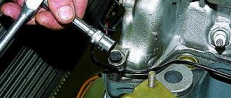
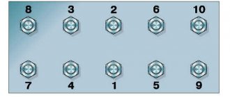
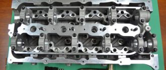
1. Remove the cylinder head.
2. Remove the engine crankcase and crankcase gasket.
3. Remove the oil pump.
4. Unscrew the nuts 1 of the connecting rod bolts and remove the connecting rod cover 2.
Since the lid fits tightly, knock it off with gentle blows of a hammer.
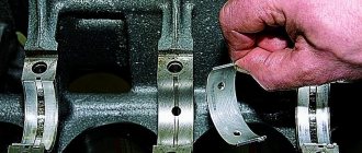
Remove the connecting rod bearing shell from the cover.
5. Push the piston into the cylinder until it comes out of the cylinder, and then remove it along with the connecting rod.
Remove the connecting rod bearing shell from the connecting rod.
The piston and connecting rod must be removed carefully from the cylinder so as not to damage the cylinder bore.
Check the marks on the connecting rod and connecting rod cap.
If the marks are not visible, mark the connecting rod and cover with the cylinder number.
6. In the same way, remove the remaining pistons with connecting rods.
7. Using a puller, remove the piston rings.
8. Remove the retaining rings from both sides of the piston.
9. Press out the piston pins using a special tool.
If there is no device, you can knock out the piston pins with light blows of a hammer through mandrel 1.
Remove connecting rod 2 from piston 3.
10. In the same way, remove the remaining pistons from the connecting rods.
11. After disassembling, wash all parts in gasoline.
Clean the pistons from carbon deposits.
Clean the piston ring grooves with an old piston ring or a broken ring.
Size groups of pistons, connecting rods and fingers
| Finger diameter, mm | Hole diameter, mm | Marking | ||
| in the top head connecting rod | in the piston boss | pin, connecting rod and piston | piston | |
| 22,0000-21,9975 | 22,0070-22,0045 | 22,0000-21,9975 | White | I |
| 21,9975-21,9950 | 22,0045-22,0020 | 21,9975-21,9950 | Green | II |
| 21,9950-21,9925 | 22,0020-21,9995 | 21,9950-21,9925 | Yellow | III |
| 21,9925-21,9900 | 21,9995-21,9970 | 21,9925-21,9900 | Red | IV |
How to check the flatness of the cylinder head.
Repairing a cylinder head, as you understand, is a long, tedious job that requires special care. If you think it’s like pissing two fingers, you’re very mistaken. I'll tell you why. First you need to remove the head; on some cars it is easier to remove the entire engine than to remove only the head. The removed head must be thoroughly washed with diesel fuel or, better yet, gasoline, but it would be very good to put it in a bath with caustic soda.
Next is a visual inspection and diagnostics. Aluminum heads have this feature or property - after overheating, the plane of the cylinder head is slightly curved, after which the cylinder head gasket (cylinder head) begins to leak oil and water in small or large quantities. Oil and coolant can leak both outside (as a result, the engine becomes dirty and shows that it needs repair) and inside the engine, where the coolant will fall into the oil pan and mix with the engine oil, turning into engine poison, which will ruin your car's engine very quickly.
It is necessary to check the plane, for this I have a special ruler that is perfectly flat, made at the ultra-precision instrument factory specifically for measuring the unevenness of flat surfaces. How a person who does not have such a device can measure the plane of the cylinder head, I don’t even know. But if you still find something suitable with a perfectly flat surface, then do the following: 1. Clean the plane of the head from carbon deposits, scale and remnants of the old cylinder head gasket. 2. On the cleaned cylinder head plane, place your “measuring device” along the length of the head and look at the gap between the device and the cylinder head plane, move the device along the entire plane, place it diagonally and look for the gap again. If there is no gap, then the cylinder head plane is in order; if there is a gap of 0.5-1mm, then it is better to trim the head or, if finances allow, to install a new one. if the gap is more than 2mm, then the head needs to be restored, that is, it must be trimmed. When facing the cylinder head, the curved layer of the plane is removed, after which the cylinder head can be used again. PS A driver who checks the engine oil at least once a week, seeing that the amount of oil has doubled and the radiator is half empty, will simply add more antifreeze to the radiator and move on, and in a few days he will be sent for repairs and spare parts.
How to find out if the cylinder head gasket is blown
You can determine whether the cylinder head gasket is blown by using one of several methods. In this case, diagnostics are simple and can be done by anyone, even a novice and inexperienced driver.
To check the integrity of the gasket, you must do one of the following:
- With the engine running, visually inspect whether smoke is coming from the gap between the cylinder head and the cylinder head . Also listen to see if there are loud ringing sounds coming from there that were not there before.
- Inspect the surfaces of the radiator caps and expansion tank of the cooling system, as well as the neck for filling oil into the engine. To do this, you just need to unscrew them and visually inspect them. If antifreeze gets into the engine, there will be a reddish emulsion on the oil filler cap. If oil gets into the antifreeze, then there will be oily deposits on the radiator or expansion tank caps.
White smoke from the exhaust pipe
How to check a cylinder head gasket using a condom
One of the effective and popular testing methods is the method using a balloon or a condom. It is put on the neck of the expansion tank, having first unscrewed the cap. The main thing is that the condom sits tightly on the neck and provides a tight seal (instead of a condom, you can use a bag or a balloon, but the diameter of the condom is usually ideal for the neck of the tank). After you put it on the reservoir, you need to start the engine and let it run for a few minutes at 3.5 thousand rpm. Depending on the level of depressurization, the condom will fill with gases quickly or slowly. It depends on the specific situation. In any case, if it begins to fill with exhaust gases, this means that the cylinder head gasket is broken.
Checking the cylinder head gasket with a condom
Checking the gasket with a bottle
Another method for determining whether the cylinder head gasket is broken is often used on trucks . To do this, it is enough to have a small bottle of water (for example, 0.5 liters). As a rule, expansion tanks have a breather (a tube that helps maintain the same pressure as atmospheric pressure in a closed container). The method is very simple. With the engine running, place the end of the breather in a container of water. If the gasket is broken, air bubbles will begin to come out of the tube. If they are not there, then everything is in order with the gasket. If at the same time coolant begins to appear from the breather, this also means that everything is in order with the gasket.
Checking the cylinder head gasket on trucks
Testing with a bottle
The two methods described above are suitable for diagnosing a malfunction when exhaust gases break into the cooling jacket. These methods are very effective and have been used by motorists for decades.
How to check the cylinder head on a VAZ 2114 – Repair 2114
To complete the cylinder head inspection job you will need:
- set of flat probes
- special template or wide metalwork ruler
- Removing the cylinder head
- We clean the block head from dirt and carbon deposits, wash it of oil deposits, and use a metal brush to remove carbon deposits from the walls of the combustion chambers.
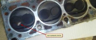
- We carefully inspect the cylinder head. There should be no cracks on it. There should be no scoring or traces of metal envelopment on the working surfaces of the camshaft supports and the walls of the mounting holes of the pushers. The valve guides and seats must sit tightly in the body of the head, without any traces of their displacement during timing operation. Valves and their seats must not have cracks or burn marks.
- Check the flatness of the head. We carry out the work in two stages. For this, a special template is needed, but if it is not there, then you can check the lower rest of the head and the exact plane of the head with a sufficient degree of accuracy using a wide bench ruler. We apply the ruler diagonally, edge to the plane of the head. We make sure that there is no gap between the edge of the ruler and the plane of the head. The gap can be observed both in the middle part of the plane and along its edges. We measure the gap along both diagonals with a set of flat feeler gauges.
The maximum permissible gap is 0.1 mm. If the gap is greater than permissible, the head must be milled or replaced.
We make sure that there is no kerosene leakage from the block head.
If a leak is detected, as well as if cavities are found on the mating plane, you can try to repair the block head using cold welding or replace it.
Checking the cylinder head
| Rice. 2.121. Removing carbon deposits from the walls of combustion chambers |
Remove all carbon deposits from the walls of the combustion chambers (Fig. 2.121).
| To remove carbon deposits, do not use tools with sharp edges. When removing carbon deposits, be careful not to leave scratches or nicks on the metal surface. The same applies to valves and valve seats. |
| Rice. 2.122. Checking the sealing surface of the cylinder head from plane |
Check the cylinder head for cracks in the intake and exhaust ports, combustion chambers and on the surface of the head. Using a straight edge and feeler gauge, check the flatness of the cylinder head parting surface in a total of 6 places. If the deformation exceeds the limit, adjust the sealing surface with a plate and approximately 400-grit sandpaper (Waterproof Silicon Carbide Sandpaper): Wrap the plate with sandpaper and sand the sealing surface to remove any raised areas. If after this the measurement results are not normal (exceed the limit value), replace the cylinder head. Leakage of combustion products through the connector plane of the head and cylinder block is often a consequence of deformation of the sealing surfaces: such leakage leads to a decrease in engine power (Fig. 2.122). Limit value of deviation of the sealing surface of the cylinder head from the plane: 0.03 mm.
| Rice. 2.123. Checking the deformation of the seating surfaces of the intake and exhaust manifolds on the cylinder head |
Deformation of the manifold seating surfaces: Check the manifold seating surfaces on the cylinder head using a straight edge and feeler gauge to determine whether the surfaces can be straightened or whether the cylinder head needs to be replaced (Fig. 2.123). Limit value of deformation of the seating surfaces of the intake and exhaust manifolds on the cylinder head: 0.05 mm.
Inspection, testing and repair
1. Inspect the pistons.
If they have burrs, burn marks, deep scratches, replace the pistons.
Measure the diameter of the piston. If it is less than 91.9 mm, replace the piston.
The piston diameter is measured in a plane perpendicular to the piston pin axis, 8.0 mm below the piston pin axis.
The piston is installed in the cylinder with a gap of 0.024–0.048 mm.
In order to ensure the size of the gap, the pistons are divided by diameter into five size groups A, B, C, D and D.
The letter marking is stamped on the bottom of the piston.
When selecting a piston to a cylinder, the above clearance must be ensured.
The maximum permissible gap between the piston and cylinder is 0.25 mm.
The gap between the piston and cylinder can be determined by measuring the piston and cylinder.
Spare parts include pistons of two repair sizes: with a diameter increased by 0.5 mm and by 1.0 mm.
On one of the bosses under the piston pin the inscription “406” (piston of nominal size), “406AP” (piston increased by 0.5 mm), “406BR” (piston increased by 1.0 mm) is cast.
2. Measure the gap between the piston ring and the groove on the piston in several places around the circumference of the piston.
The gap should be in the range of 0.05–0.087 mm for compression rings and 0.115–0.365 mm for the oil scraper ring.
If the clearances exceed the specified values, the rings or pistons need to be replaced.
3. Measure the gaps in the piston ring locks.
To do this, insert the ring into the cylinder and push it with the piston as a mandrel so that the ring fits evenly in the cylinder without distortion.
Measure the gap in the ring lock with a feeler gauge; it should be in the range of 0.3–0.6 mm for compression rings and 0.5–1.0 mm for oil scraper discs.
If the gap exceeds the specified value, replace the ring.
If the gap is smaller, you can file the ends of the ring with a file held in a vice.
In this case, the ring is moved up and down along the file.
4. Check the fit of the piston pin in the upper head of the connecting rod.
The gap between the pin and the bushing of the upper head of the connecting rod should be in the range of 0.0045–0.0095 mm.
Pins, pistons and connecting rods are divided into four size groups and marked with paint.
The pin is marked on the inner surface at one end, the connecting rod is marked on the rod, the piston is marked on the lower surface of one of the bosses, or a Roman numeral is stamped on the bottom of the piston.
The size groups of pistons, connecting rods and fingers are shown in the table. Lightly lubricate the piston pin with engine oil and insert it into the upper end of the connecting rod.
The finger should enter the head using the force of the thumb evenly, without jamming. The connecting rod must rotate on the pin under its own weight from a horizontal position.
The pin should not move out or fall out of the connecting rod head under its own weight when the connecting rod is turned so that the pin is vertical.
The piston pin and connecting rod must be of the same or adjacent size groups.
5. Pistons with piston rings, pins and connecting rods assemblies are selected based on weight. The difference in weight for one engine should be no more than 10 g.
6. Inspect the connecting rod bearings. If they have burrs, marks, chipping, etc., they need to be replaced.
7. Install the caps on the connecting rods and measure the diameter of the hole in the lower head of the connecting rod. The nominal hole diameter is 60 +0.019 mm, the maximum permissible is 60.03 mm.
If the measured diameter exceeds the maximum permissible, replace the connecting rod with the cap.
Measure the diameter of the hole in the bushing of the upper connecting rod head. The nominal hole diameter is 22 +0.007 and 22 –0.003 mm, the maximum permissible is 22.01 mm. If the measured diameter exceeds the maximum permissible, replace the connecting rod. The dimensions of the connecting rod and piston group are given in the table.
How to check the cylinder head after grinding?
In principle, checking the cylinder head is not so difficult.
Clean the cylinder head from dirt, oil, and chips. Carefully inspect the head from all sides to ensure that there are no holes or cracks.
In specialized workshops, the plane of the block head is checked with a special template.
At home, when this template is not available, you can check the flatness with a wide, long metal ruler. It must be applied to the plane of the head with its edge; the figure shows in which places to apply it
And check the gaps with a feeler gauge. The gap is checked along the entire perimeter. Ideally, there should be no gaps. But if there is a gap of no more than 0.01 mm, then this is allowed.
