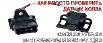
Checking the Hall sensor and replacing it
The Hall sensor is one of the most important elements of the contactless ignition system for gasoline engines.
The slightest malfunction of this part leads to serious problems in the operation of the motor. Therefore, in order to avoid diagnostic errors, it is important to know how to check the Hall sensor and, if necessary, to be able to replace it. We divided this material into two parts: theoretical (purpose, design and principle of operation of the Hall sensor) and practical - signs of malfunction, verification methods and replacement methods.
At the end of the article, watch the video instructions on how to replace the Hall Sensor yourself.
And before checking the Hall sensor for malfunctions, let's understand its purpose and operating principle.
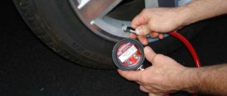
What happens if the DPKV breaks down?
Signs of malfunction can be divided into two groups:
- The sensor has failed, so no pulses are received at all. In this case, the engine will simply stall, and you will not be able to start it until the breakdown is repaired. DPKV is the only sensor that, if it malfunctions, the internal combustion engine will not be able to operate even in emergency mode.
- The sensor malfunctions or provides incorrect information. The engine will start and run with obvious symptoms of a malfunction: loss of traction;
- power reduction;
- floating idle speed;
- The “Check Engine” warning light is on.
In addition, the engine may stall at any time for no apparent reason.
If you connect a car scanner to the OBD port, it will generate an error code 0335, which can be forcibly reset, but will appear again when the engine starts.
What is a Hall sensor and how does it work
The Hall sensor (also known as a camshaft position sensor) is one of the main elements of the distributor. It is located next to the distributor shaft, on which a magnetically conductive plate, similar to a crown, is attached. There are as many slots in the plate as there are cylinders in the engine. There is also a permanent magnet inside the sensor.
The principle of operation of the Hall sensor is as follows: when the shaft rotates, metal blades alternately pass through a slot in the sensor. As a result, a pulse voltage is generated, which enters the ignition coil through the switch and, converted into high voltage, is supplied to the spark plugs.
The Hall sensor has three terminals:
- one connects to the “mass”,
- the second is approached by a plus with a voltage of about 6 V,
- The converted pulse signal goes from the third terminal to the switch.
How does he work
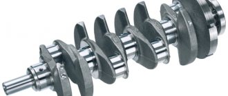
In order for the ignition timing to work synchronously with the movement of the pistons in the cylinders, information about the position of the crankshaft at each moment of time is necessary. There is a rigid mechanical connection between the connecting rods and the crankshaft: to track them, it is enough to read the angle of deviation of the crankshaft axis from the zero point.
For this purpose, a gear (58 teeth) is placed on the timing belt drive pulley. They do not participate in the operation of the timing pulley and are intended only for the crankshaft position sensor (CPS).
The position of these teeth is strictly calibrated relative to the entire timing system and piston connecting rods. The device itself is a Hall sensor with a permanent magnet that responds to the passage of a metal object in close proximity. That is, the rotation of the crankshaft with a gear generates a series of pulses on the sensor. As a result, the ECU receives data on the position of the pistons in real time.
Signs of a Hall sensor malfunction
Hall sensor malfunctions manifest themselves in different ways. Even an experienced technician will not always immediately identify the cause of engine problems.
Here are some of the most common symptoms:
- The engine starts poorly or does not start at all.
- At idle, the engine runs rough and jerky.
- The car may jerk when driving at high speeds.
- The power unit stalls while driving.
If one of these signs appears, you must first check the serviceability of the Hall sensor.
Also, do not exclude other malfunctions of the ignition system found in cars.
How to check the Hall sensor
A simple way to check the camshaft position (Hall) sensor is shown in the following video.
There are several ways to check the health of the Hall sensor. Each motorist can choose the most suitable option for himself:
- Take a working sensor from a neighbor or at a car disassembly for testing and install it instead of the “native” one. If the engine problems disappear, then you will have to buy a new part.
- Using a tester, you can measure the voltage at the sensor output. In a working device, the voltage will vary from 0.4 V to 11 V.
- You can create a simulation of a Hall sensor. To do this, remove the three-pin block from the distributor. Then turn on the ignition and connect outputs 3 and 6 of the switch with a piece of wire. The appearance of a spark indicates that the sensor has failed.
If the test reveals that the Hall sensor is faulty, then it must be replaced with a new one.
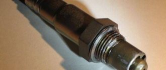
Where is the DPKV located, how to change it
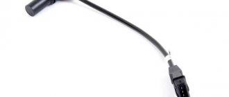
The sensor is located near the timing belt pulley on the generator side.
A corrugated cable is stretched to its connector, the location is open, accessible from the engine compartment. The sensor is attached with one bolt to the crankcase body. Before removal, you must carefully disconnect the connector; dismantling other components is not required.
After removing the DPKV, you need to make sure that the contacts and the outside of the housing itself are clean. If necessary, clean and recheck the sensor.
If the symptoms do not disappear, the sensor must be replaced with a new one. The electronics inside the case cannot be restored.
An initial check is possible using a multimeter. A working sensor shows resistance at the contacts between 300 Ohm and 1 kOhm. When a metal object is brought to the end of the sensor, the resistance increases.
After installing the DPKV, no additional configuration is required. It is necessary to start the engine and let it idle for several minutes. Then the engine is turned off and started again. The sensor is calibrated by the ECU program automatically.
Hall sensor replacement
Replacing the Hall sensor will not be particularly difficult. Even a novice car enthusiast can handle this work with his own hands.
The video below shows in some detail the process of replacing the sensor in the distributor of a UAZ car.
Typically, replacing a Hall sensor consists of several steps:
- First of all, the distributor is removed from the car.
- Next, remove the distributor cover and align the timing mechanism mark with the crankshaft mark.
- Having remembered the position of the distributor, you need to unscrew the fasteners with a wrench.
- If there are latches and stoppers, they should also be removed.
- The shaft is pulled out of the distributor.
- All that remains is to disconnect the terminals of the Hall sensor and unscrew it.
- By pulling back the regulator, the faulty part is carefully removed through the gap formed.
- The new Hall sensor is installed in the reverse order.
Checking the functionality of the Hall sensor not only allows you to accurately determine the cause of engine failure. Thanks to simple techniques, the motorist will save his time on repairs and also eliminate unnecessary waste of money.
Replacement
There is nothing particularly difficult about replacing the DH on a domestic nine. Therefore, even a novice driver can take on the job with his own hands.
- Disconnect the negative terminal from the battery.
- Disconnect the armored wires from the distributor, disconnect the hose from the vacuum corrector.
- Next, remove the gas cable and put it aside for now so as not to interfere with the process.
- Unscrew the bracket fasteners that hold the wires. Remove the bracket from the stud and move it aside. Otherwise he will disturb you.
- Be sure to draw a straight line on the auxiliary drive housing and distributor. This location will allow you to avoid disturbing the ignition timing during reassembly.
- Disconnect the power supply with wires.
- Remove the plugs from the clutch housing and turn the flywheel with a screwdriver so as to set the piston of the first cylinder to the top dead center position.
- To remove the distributor, you need to unscrew two more mounting nuts holding the device.
- Remove the cover from the distributor, remove the slider and pull it up. Only a little.
- Remove the dust cover.
- Now unscrew the mounting bolt to remove the plug.
- We also need to unscrew the bolts that hold the plate of our desired sensor.
- Remove the vacuum corrector mounting bolts, remove the retaining rings, corrector and rod.
- To get the wires out, you will need to release the clamp there.
- Remove the mounting plate and unscrew the mounting bolts, which will allow you to finally remove the failed Hall sensor.
- It is now necessary to install a new sensor and assemble the unit, proceeding in the reverse order.
It is important not to change the ignition settings
Don’t forget, after completing the work, be sure to check whether your carburetor VAZ 2109 is working correctly, and whether you have violated the ignition timing.
How to check and replace the Hall sensor
An article about the Hall sensor - what it is, how it functions, how to check and replace the module. At the end of the article there is a video about how the Hall sensor works.
Even minor malfunctions in the operation of this sensor can cause car damage.
In this regard, a car enthusiast should have the skills to check the performance of a part, and if necessary, be able to replace it.
Module design
The main purpose of this module in the operation of a car engine is to determine the current camshaft angle at each moment of engine operation. The module uses the information received to control the fuel injection system into the internal combustion chamber and activate the ignition. Fuel injection is carried out into the cylinder, which is currently located at the so-called “dead” point.
The module’s operation is based on the Hall principle, discovered back in the 19th century.
This sensor began to be actively used by car engine developers starting from the late seventies - the first half of the eighties of the last century. At that time, contact-type ignition systems previously used in automobile internal combustion engines began to be actively replaced by new, more reliable and safe contactless units, in which the Hall sensor played a major role.
The second name of the Hall sensor is a sensor that determines the position of the camshaft.
The English abbreviation for the name of this module is SMR. This part performs the function of generating and subsequently distributing voltage pulses that control the operation of the spark plugs and the automotive switch.
There are slots in the body of the device through which metal plates pass during operation of the motor shaft. The number of slots in the module coincides with the number of cylinders in the internal combustion engine. A magnetic plate is built into the sensor.
When the shaft rotates and the plates pass through the slots in the device, an electrical voltage is generated. Depending on the information obtained as a result of this process, the device supplies the switch with an unlocking electric pulse for the transistor, and voltage is applied to the ignition system to the coil. The resulting low-voltage signal, when transmitted to the spark plug, is converted into a high-voltage pulse.
The camshaft position sensor has three contacts:
- contact connected to the vehicle body;
- the terminal that receives a positive charge of 6 V;
- contact from which a modified electrical pulse is supplied to the switch device.
The use of a Hall sensor in ignition systems with an electronic operating principle gives the vehicle design two significant advantages:
- It avoids the use of a contact group, which is short-lived due to the fact that it constantly burns out during engine operation.
- This device allows you to provide a voltage of 30 kV to the spark plug, and not 15, as when using other design circuits.
In addition to the ignition system, the Hall sensor is also used in the tachometer, the anti-lock braking system and the braking system of the car. It provides increased engine performance and allows all vehicle systems to operate at a higher speed. As a result, the safety and ease of use of the car engine increases.
The principle of operation of the sensor and its features
In its operation, the sensor uses the physical Hall effect, discovered in the 19th century. However, they began to use it only in the 70-80s of the last century, when automakers began to switch from contact ignition systems to electronic ones.
Read more: Tires K 139 for Niva reviews
The principle of operation of the sensor is quite simple. As the motor shaft rotates, metal blades pass through slots in the motor housing. It gives an electrical impulse to the switch, as a result of which the latter unlocks the transistor and supplies voltage to the ignition coil. It, in turn, converts the low-voltage signal into a high-voltage one and supplies it to the spark plug.
Structurally, the sensor has three contacts:
- for connection to “ground” (car body);
- to connect voltage with a “+” sign and a value of about 6 V;
- to supply a pulse signal from it to the switch.
The advantages of using a Hall sensor in electronic ignition systems are two main factors - the absence of a contact group (which constantly burns out), as well as a higher voltage on the spark plug (30 kV versus 15 kV).
Since Hall sensors are also used in braking and anti-lock braking systems and tachometer operation, the device performs the following additional functions for the car:
- increases engine performance;
- speeds up the functioning of all machine systems.
As a result, the ease of use of the car, as well as its safety, increases.
Hall sensor for VAZ 2107
Hall sensor for VAZ 2109
Hall sensor for VAZ 2110
Module failure detection
A malfunction in the functioning of the Hall sensor causes extremely unpleasant consequences: the car stops starting or stalls. The engine stops working.
You can suspect problems with the sensor based on the following indirect signs:
- fuel consumption is unreasonably high, and the increase in consumption is observed suddenly, spasmodically;
- when the engine is running, the temperature rises too much, and this increase is observed consistently (this symptom is very unpleasant and requires contacting a service station as quickly as possible or self-diagnosis of the Hall sensor);
- on some car models, the gearbox mode switch can be fixed without the possibility of changing its position until the engine is stopped and restarted;
- the car engine does not start the first time or does not start working at all;
- at idle speed there are jerks and interruptions in operation;
- at high engine speeds the car moves jerkily and twitches;
- during normal operation the engine suddenly stalls;
- The corresponding alarm indicator lights up on the dashboard, and it lights up at idle speed, and turns off when the speed is increased.
If any of the above symptoms are observed while driving, you should immediately check whether the Hall sensor is working properly. At the same time, do not forget that there may be other problems in the ignition system, so in any case you cannot limit yourself to just checking the condition of the camshaft position sensor.
Homemade tester from LED and indicator
The performance of the device can be checked by its resistance. This procedure requires making a simple device, which consists of a resistor with a resistance of 1 kOhm, as well as an LED and two wires of sufficient length.
Diagnostics must be performed using the following algorithm:
- you need to solder the resistor directly to the LED leg;
- connect wires to it;
- then you can remove the ignition distributor cap, disconnect the distributor, plug box;
- check the serviceability of the electrical circuit by connecting a voltmeter or multifunction tester to the first and third terminals;
- turn on the car ignition.
After the procedures described above have been carried out, the device screen should normally display 10-12 Volts. At the next stage, move the wire from the third terminal to the free second one, and then rotate the camshaft.
If the Hall sensor is working properly, the LED should start blinking.
Methods for checking the Hall sensor
Perhaps the easiest way to check a part is to use a known-good sensor from another car. If, when replacing a part, the engine starts to work as required, the most logical thing would be to recognize the removed Hall sensor as faulty.
One of the most commonly used testing methods is the method using a voltmeter or multimeter. You can check the sensor with a multimeter in two different ways:
The first method is with connection to the ignition system
For testing, you will need a voltmeter and two iron nails, which will act as probes at the main testing stage. The multimeter should be set to a mode that allows you to determine DC current readings in the 20 volt range.
Before checking, it is necessary to remove the rubber boot installed on the block connected to the distributor and sensor. Next, the main armored wire is removed from the distributor, which is connected to the arrester or to the car body. These precautions are necessary to prevent accidental discharge, which could accidentally start the engine during testing.
After this, you need to make sure that the sensor under test receives all the necessary pulses. For this:
- set the multimeter to DC mode 20 V;
- turn on the ignition;
- remove the block from the distributor;
- align the probe connected to the negative of the device with the car body;
- the probe connected to the positive part on the red wire of the distributor block should show about 12 V;
- the probe connected to the positive part on the green wire of the distributor block should show about 12 V;
- The probe connected to the positive part on the white wire of the distributor block should show 0 V.
This check is preliminary. Next, you need to determine in what range the readings of the measuring device change when the crankshaft is turned. To do this, you need to insert the prepared nails into the middle wire (green color) and into the white wire. The block should be connected back to its place.
When the conductors are installed, with the ignition on, connect the plus of the multimeter to the stud of the middle wire, and the minus to the white one. The multimeter reading should be about 11 V. Next, we test the device while turning the crankshaft. The readings should be in the range from 0.02 to 11.8 V. With a range of 0.4 - 9.00 V, the device is also considered to be working.
The second method is without connecting to the ignition system
To operate, you will need an assembly of three contacts connected to the electrical terminals of the removed device.
The multimeter probes are connected to the test points. The blade of the knife must be drawn along the slot of the device, measuring the readings of the multimeter with the sensor curtain closed and open. The measurement range should be 0.4 – 9 V.
What to do if you don’t have a multimeter at hand? There is another test option - using an old processor cooler from a computer unit. The two cooler wires should be connected to the sensor distributor block. When the ignition is turned on, the cooler will work.
If there is power in the ignition system, but there is no spark, you can check the condition of the device as follows:
Remove the 3-pin block from the distributor, activate the ignition and use a piece of wire to close the signal and minus contacts (outputs 2 and 3, respectively). If a spark appears on the center wire as a result, we can conclude that the sensor is faulty.
You can check the functionality of the sensor in conjunction with the operation of the switch using a regular 3 W light bulb with wires.
You need to disconnect one of the wires from the coil in the car (not the B+ terminal) and connect it to the light bulb wiring. Connect the second wire to terminal B+ and turn on the car starter. If the lamp blinks, then the sensor + switch duo is working properly. Otherwise, the problem is in one of the devices.
In parallel with testing the sensor, you should make sure that the entire complex of equipment is in good working order, paying special attention to the condition of the electrical wiring, the condition of the fuses and the cylinder head, the condition of the lock and ignition key, as well as the battery charge level.
The easiest method with a multimeter
The most popular way to check the condition of the Hall sensor is to use a multifunction tester:
- To carry out the procedure, you can dismantle the device.
- Then connect the positive contact of the tester to the signal output, and the negative contact to the common one.
- In this case, the voltage measurement range must be set within 12 Volts.
- If the device is working properly, the readings should be in the range of 0.4-11 Volts.
Installing a new Hall sensor to replace the faulty one
If a malfunction is detected, the part must be replaced with a new one. The procedure for this work, as a rule, does not pose any particular problems even for inexperienced car owners. To work, you will need pliers, a Phillips and flat-head screwdriver, and 6-13 mm wrenches to remove the ignition distributor from the car.
The procedure is as follows:
- disconnect the negative terminal of the battery;
- dismount the high-voltage wires from the distributor cover;
- unscrew the nuts that hold the distributor in its working position;
- dismantle the distributor;
- the crankshaft should be turned until the timing cover mark aligns with the pulley mark;
- indicate the location of the runner (camshaft rotor);
- disassemble the distributor to remove the crankshaft from it;
- remove the sensor contacts and twist the device itself from the distributor (the faulty module is removed through the gap created when the regulator is pulled out).
In order to install a new part into the unit, you will need to perform the entire described sequence of technological operations in reverse order.
After the new sensor has been installed, it must also be checked for functionality.
Any of the methods described above will be suitable for this. The malfunction may be due to improper installation of the sensor. If you are sure that everything was done correctly, you should seek help from professionals.
If you have determined that the Hall sensor has stopped working as expected, there is no point in repairing it - it is not that expensive, and replacing the broken part with a new one is not difficult. If you are convinced that the sensor is faulty, you should simply purchase it at the nearest auto store and replace the broken module with a new one.
Video about how the Hall sensor works:
Replacing the hall sensor on a VAZ 2101-VAZ 2107
Removal
Remove the distributor from the car. You will have to disassemble the distributor a little, read more in the article: “Repairing the distributor on cars”, points 1-3 and 5.
Note! While removing the ignition distributor, do not forget to disconnect the wire block from the sensor. For clarity, the photo below shows with an arrow the place where this block is inserted, and the blue arrow shows the block itself. We disconnect it.
Now that you have disassembled the distributor and checked the components for serviceability, proceed to removing the sensor. It is fastened with screws, by unscrewing which (see photos 1 and 2) you can remove it from the car.
Installation
Install the parts in the reverse order of removal. First check the serviceability of the sensor: although rare, there have been cases of faulty sensors being sold in car dealerships. Below are instructions that you can use to check your old sensor, it may be in working order and does not require replacement. Or check the new one after installation.
Hall sensor check
The best test is to install a different, known-good sensor in the car, start it and evaluate the engine's performance. Then everything will fall into place and you will understand whether this is where the problem lies. There is an alternative verification method. We will need a voltmeter and a sensor removed from the car. Please note the test diagram below, it explains how to connect the voltmeter: Connect the voltmeter tips to pins 2 and 3 of the sensor and insert a screwdriver or blade between the sensor contacts. Observe the readings at the time of the test, they should change in the range of 0.4-3 volts. If the readings are lower, the sensor is faulty and requires replacement. Remember, the test is carried out on the device removed from the car.
Additional video
We have attached a video that describes the verification process in detail. Please note that in this video there is no connector for the sensor, the wires come out immediately - consider them the sensor terminals.
Note! We recommend that you also watch the video below. What is presented here is not a car of the classic family, but a VAZ 21099. After looking, you will understand that the sensor is checked on all cars almost identically.
Hall sensor on the VAZ 2107: its purpose, types of breakdowns and replacement
When the Hall sensor on a VAZ 2107 breaks down, this makes it impossible to continue driving. The Hall sensor belongs to the category of key parts of a contactless ignition system, and if this part begins to fail, the switch will stop sending impulses to produce a spark. To troubleshoot the problem, you need to understand in detail the purpose and operation of the device.
Why is a Hall sensor needed and how does it work?
The device of the contactless ignition system of the VAZ 2107 car has such an element called a Hall sensor. Its fundamental purpose is the ability to detect the angle of the crankshaft and camshaft of the power unit. The Hall sensor is not installed on injection models of sevens, it is installed only on carburetor ones.
According to the value of this device, voltage pulses are supplied to the spark plugs. The functioning of this element is based on increasing the voltage in the cross-section of a wire placed in a magnetic field. The element is connected by three terminals, two of which provide power supply (plus and minus), and the third contact is intended directly for supplying a signal. The device received this name due to a special effect that was identified by scientist Hall. In the distributor on the shaft there is a plate that is part of the control of the device controller.
When the motor operates, the metal in the slots alternately changes, and the magnet, which is located inside the controller, begins to be excited by oscillations of the magnetic field. In this case, the controller generates voltage pulses issued by the switch and supplied to the coil. The coil, in turn, raises the voltage to a high value and transports it one by one through armored wires to the spark plugs. Knowing the operating features, you need to deal with the malfunctions, but before that it is important to note that the Hall sensor on the VAZ 2107 is located in the distributor under the cover. To replace it, you will need to disassemble the distributor.
Basic sensor malfunctions
Any part on a car sooner or later begins to malfunction, and the Hall sensor is no exception, even though it has the simplest design. Its breakdown is detected by detecting the following defects:
- Inability to start the engine.
- Unstable and unstable operation of the motor.
- The occurrence of jerks.
- The engine begins to stall.
- The appearance of the detonation effect.
If the above symptoms appear, then there is no need to rush to change the Hall sensor, since similar phenomena can also occur due to other breakdowns of the ignition and fuel supply system. To verify that the device is faulty, you will need to perform a suitability test.
Check Features
The BSZ contactless ignition on the VAZ 2107 has a Hall sensor, the serviceability of which determines the normal operation of the internal combustion engine. If you suspect that it is faulty, then you need to check the Hall sensor. To do this, there are different ways on the basis of which one can draw a conclusion about the suitability of the element.
Checking and replacing the Hall sensor VAZ 2107
One of the key elements of the contactless ignition system is the Hall sensor of the VAZ 2107. If this element breaks down, operation of the car is practically impossible, since the switch will not produce impulses for sparking. Let's figure out how this sensor works, how its malfunctions manifest themselves, and how you can replace the Hall sensor with your own hands.
Working principle of the Hall sensor
The device is installed on cars with a contactless ignition circuit and serves to monitor the camshaft position. It has three terminals: power, ground and output. This element works thanks to the Hall effect, which is how it got its name.
The voltage at the sensor output changes depending on changes in the magnetic field. A plate with slots installed on the shaft of the VAZ 2107 distributor enters the space of the sensor controller. As the motor rotates, the slots are constantly replaced by solid metal and a magnet installed in the controller responds to changes in the magnetic field by generating voltage pulses. When pulses arrive, the switch supplies voltage to the coil, which increases the voltage and supplies it to the spark plugs.
Signs of a malfunction of the Hall sensor VAZ 2107
If the VAZ 2107 Hall sensor (carburetor or injector) begins to fail, this manifests itself in the following:
- The engine will not start;
- the engine runs unsteadily;
- jerking is felt when moving;
- the engine suddenly stalls.
The problem is that similar manifestations also occur when other elements of the fuel supply and ignition system are in good condition. Therefore, before changing the sensor, you need to make sure that it is the problem.
Where is the Hall sensor located in the VAZ 2107 (injector and carburetor)
The sensor is fixed under the distributor cover. To access it, you need to unclip two latches and remove the cover.
How to check the sensor
The device can be checked in three ways:
- replace the sensor with a known good one (the method is good if such a part is already available);
- check whether the voltage at the sensor output corresponds to the nominal value of 0.4-11 volts (a tester is required for this);
- simulate the operation of the sensor by connecting pins 3 and 6 of the plug going to the sensor with the ignition on (if a spark occurs, the sensor needs to be replaced).
What is needed for replacement
To change the Hall sensor, you will need:
- flat screwdriver;
- pliers with extended jaws;
- new Hall sensor.
Basic functions of the device.
To control the speed of movement, a special device is installed on the dashboard - a speedometer. But it only displays the information received, and the speed sensor is responsible for collecting data. If it fails, it will create many dangerous situations on the road, since it will become difficult to control the speed limit in the city and on the highway.
But besides this, thanks to the integration of the electronic control unit into the system, the speed sensor allows you to perform the following functions:
- fuel consumption control
- displaying information on the instrument panel
- in cars with an automatic transmission it is included in the complex responsible for engine control
In case of failure, you are allowed to continue the journey, but this will become difficult.
Historically, there were two types of sensors. Initially, mechanical or optoelectronic were used. They read the number of shaft revolutions, transmitting it to the instrument panel using a cable. Then electronic cableless systems came to replace them.
Replacing the Hall sensor on a VAZ 2107
Once you have confirmed that this particular part is faulty, you need to replace it. It is better to carry out the work by first removing the distributor from the car. To replace the Hall sensor of a VAZ 2107, you must perform the following steps:
- unclip the distributor cover fastenings;
- remove the cover;
- remove the rotor (“runner”), pulling it towards you with a little force;
- remove the black plastic cover;
- Using a flat screwdriver, unscrew the bolts holding the plug and wire block;
- unscrew a pair of bolts holding the sensor support plate;
- unscrew the two bolts holding the distributor vacuum corrector;
- Use pliers with long jaws to remove the retaining ring from the hole;
- remove the vacuum corrector tag located on the pin of the support plate;
- dismantle the corrector;
- Use a screwdriver to remove the electrical wiring from the clamp on the distributor;
- pull the support plate up along the distributor axis and remove it;
- Unscrew a pair of bolts securing the Hall sensor using a flat screwdriver;
- remove the Hall sensor.
To install the Hall sensor, you need to do the above steps in reverse order.
Hall sensor VAZ 2109 - replacement without the help of specialists
VAZ 2109 cars equipped with carburetor engines have a contactless ignition system with a Hall sensor.
The main task of the VAZ 2109 Hall sensor is to supply control pulses to the switch, which converts the received pulses and directs them to the primary winding of the ignition coil. This microelectronic sensor is located in the housing of the ignition distributor sensor under the dust shield. Depending on the type of distributor, it is secured to the base plate using 2 screws or rivets. The operation of replacing the Hall sensor of a VAZ 2109 is not difficult. The replacement can be done within half an hour by any car enthusiast without the help of specialists.
Sensor check
It is not always the case that if the Hall sensor malfunctions, the car’s power unit does not start. There may be problems with ignition, such as interruptions in engine operation in any mode, absent or unstable idling, as well as loss of power. There are two ways to check the Hall sensor. The first is suitable for those who do not have special knowledge in the field of auto electrics and electronics.
With this method, you need to purchase a new and known-good sensor from an auto parts store and install it correctly in place of the old one. If the engine starts after this operation, then the problem is solved. If not, then the problem is in the resistor, switch, coil, ignition switch, wires, spark plugs or other parts of the distributor.
https://youtube.com/watch?v=DiWtCGGKN6s
The second method of checking the VAZ 2109 Hall sensor requires special knowledge in electrical engineering. In addition, to carry out self-diagnosis, you must prepare the following instruments and devices:
- a voltmeter or multimeter with a measurement limit of at least 15 V and an internal resistance of at least 100 kOhm;
- 3-pin block from the distributor with low-voltage wires;
- resistor with a resistance of 2 ohms.
The check must be carried out as follows.
- First you need to remove the distributor from the car.
- Then you need to connect a block with wires, a resistor and a voltmeter to the connector of the low-voltage wires according to a certain circuit.
- After this, you need to apply voltage from the battery (9-14 V) to the positive contact and slowly turn the distributor shaft.
- During this operation, you need to record the minimum and maximum voltmeter readings.
Normally, the minimum voltage should be less than or equal to 0.4 V, and the maximum should not differ from the voltage supplied from the battery by more than 3 V. If, when turning the distributor shaft, there is no sharp voltage jump or the minimum and maximum values differ from the norm , this means that the sensor is broken and should be replaced.
Replacing the device
Replacing the Hall sensor
In order to replace the Hall sensor, you first need to remove the distributor from the drive of the auxiliary units. The dismantling algorithm is as follows.
- First of all, you need to disconnect the terminals from the battery.
- Then you need to remove the armored wire from the cover of the breaker-distributor and unhook the hose from the vacuum corrector.
- Then you need to remove the throttle cable from the holder so that it does not interfere, unscrew the nut securing the bracket on which the wires are held, remove the bracket from the stud and move it to the side.
- Next, you need to scratch with a screwdriver or draw a straight line with a marker, passing from the distributor body to the drive housing of the auxiliary units. This mark will allow you to maintain the same ignition timing during installation of the distributor.
- After this, you need to unhook the block with wiring from the breaker-distributor.
- Then you need to remove the dirt plug from the clutch housing hatch and use a screwdriver to turn the flywheel until the piston of the first cylinder is in the top position.
- Now you need to unscrew the 2 remaining nuts and remove the distributor.
After dismantling the unit, you can begin replacing the sensor; to do this, you need to follow a sequence of actions.
- Unscrew the screws and remove the distributor cover.
- Pull the slider up and remove it, then remove the dust shield.
- Remove the low-voltage wire connector by unscrewing the screw.
- Unscrew the screws securing the support plate and remove the ring from its pin.
- Unscrew the screws of the vacuum corrector, remove its rod from the plate pin and remove it from the body.
- Lift the plate with a screwdriver and also pull it out of the case.
- Unscrew the screws securing the sensor and replace it with a new one.
If the sensor is attached to the plate with rivets, then they need to be replaced as an assembly. Installation of the device should be carried out in reverse order. Before installing the distributor, you need to turn the outer contact of the slider to the terminal of the first cylinder.