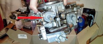
How to easily check the Hall sensor yourself: tools and instructions
Good day to all! Today I’ll tell you how to check a Hall sensor, what methods exist for assessing the condition of a device, and what you should pay attention to.
Motorists and those who ride a scooter and have a contactless ignition system or electronic ignition in their vehicle design have probably heard about this sensor or controller. It is also often called the camshaft position sensor or simply the camshaft position sensor.
The device is even found on phones. But since we have an automotive website, we will talk about the Hall sensor specifically in relation to cars and vehicles.
Before touching on the topic of verification methods, it would not be amiss to understand the very essence of the device in question, its functions and operating principle.
What it is
A Hall sensor is a controller that is located in the distributor and is one of its key components. The distributor, in turn, is a breaker-distributor.
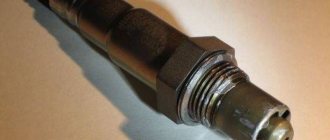
The Hall sensor (HL) is located directly near the distributor shaft, where a special magnetically conductive plate is attached. Outwardly, it resembles a crown. This plate has exactly the same number of slots as the number of cylinders in a particular power plant. Therefore, if you have a car with 6 cylinders, then there will be exactly 6 slots. A permanent magnet is installed directly inside the controller.
Now regarding the principle of operation. If you understand this issue a little, you won’t see anything complicated here.
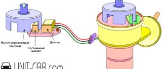
When the shaft rotates, the metal blades pass alternately through the slots in the controller in question, that is, in the DC. As a result of rotation, a pulse voltage is generated.
This voltage, due to the presence of a switch, goes directly to the ignition system coil. This is where the conversion process to high voltage takes place. As a result, it ends up on the spark plugs. The design of the DC provides for the use of 3 different terminals at once. The first serves to connect to ground, and the second receives a plus, receiving a voltage with a nominal value of about 6 V. There is also a third terminal from which the pulse signal goes to the switch after conversion.
This is roughly how we can describe the operating principle of the sensor in question.
Symptoms of malfunctions
Symptoms of problems associated with this sensor can manifest themselves in a variety of ways. Sometimes even experienced auto repairmen cannot understand the first time why the engine is running intermittently.
DHs are installed on a number of vehicles:
- on Niva from AvtoVAZ;
- VAZ 2109 (carburetor and injector);
- Volkswagen Passat B3;
- Audi 80;
- Mazda 626;
- Volkswagen Golf 3rd generation;
- Mazda 323;
- VAZ 21099;
- Volkswagen Bora;
- Chevrolet Niva;
- Opel Cadet, etc.
Before checking the device, there must be appropriate reason to suspect the Hall sensor is the problem.
The machine usually makes itself clear that the device requires replacement or at least diagnostics.
There are several main symptoms of malfunctions.
A motorist can learn about possible problems with the hall sensor by the following signs:
- the engine stalls;
- the engine does not want to start at all;
- when idling, interruptions are felt;
- the engine idles jerkily;
- when driving, the car jerks when the speed increases;
- the engine just stalls when you drive down the road;
- the car shakes a little;
- it is either pulled forward or backward, although the gas pedal is in the same position.
These are, of course, indirect signs, but you definitely need to pay attention to them. One of the first suspects in such situations will be DH.
How to check and replace the Hall sensor on a VAZ 2107?
The Hall sensor of the VAZ 2107 is one of the most necessary components in the car’s ignition system. If it fails, then interruptions in the operation of the power plant may begin and it is quite possible that the car will stop completely.
The Hall sensor on the VAZ 2107 is a control device that is a camshaft controller, which is installed near the distributor and guarantees its correct operation. The breaker-distributor shaft has a special plate in the shape of a crown. This plate has special slots, and there is a magnet on the camshaft controller. As the camshaft rotates, metal vanes enter the controller space. As a result, a pulse voltage is generated that goes to the ignition coil, and it is converted into an increased voltage. The ultimate goal is the spark plugs.
Ignition operation diagram
It should be noted that the VAZ 2107 camshaft controller has only 3 terminals. One is connected to the minus, and the other supplies a voltage of six volts, the 3rd one transmits the impulse directly to the switch.
VAZ Hall sensor
Verification methods
You can use several diagnostic methods for the sensor located on the distributor.
Depending on the available means and capabilities, the motorist can check the current condition of the Hall controller with his own hands, evaluate its performance and make the appropriate decision on replacement.
As soon as you notice one or more of the symptoms presented, you should get checked. You can do it in several ways. I propose to consider them separately.
Wedge with wedge
The simplest and most effective method that does not require you to equip yourself with a tester or multimeter. But you will need a known-good similar Hall sensor.
The essence of diagnosis is outrageously simple. You remove the old controller and install a new one in its place. If after the manipulation the symptoms go away and engine operation returns to normal, then simply leave the new part in place. If you borrowed a DH from a friend or neighbor in the garage, remove the device, say thank you, and go to the auto parts store.
Voltmeter and multimeter
Using a voltmeter or a classic tester, you can easily check the condition of the device.
I think every motorist can use the tester. The task is to measure the voltage at the sensor output.
If the DC is in good condition, the tester will produce values in the range of 0.4-11 V.
A universal multimeter is used in exactly the same way. You just need to select the voltmeter mode on it.
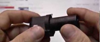
Sensor simulation
Quite an interesting and effective method. But here you will have to do a little work with your own hands.
The principle of imitation is as follows. First, remove the block from the DH, which has 3 plugs. Next, start the ignition on the car, then connect outputs 3 and 6 to each other.
If a spark appears during such manipulation, then most likely the DC has failed.
Without testers
When testers are not available, testing can be done using a slightly different method.
Here you need to carry out step-by-step manipulations:
- the spark plug is connected to the wire terminal from the coil;
- the threaded part of the spark plug is connected to the ground;
- the carriage with the sensor is dismantled;
- connector is connected;
- the ignition is turned on;
- a metal object is held near the sensor;
- When a spark appears on the spark plug, the DH is operational.
Just be extremely careful when doing such manipulations with your own hands.
Homemade tester
You can assemble an analogue of the tester from practically available materials.
The testing device consists of a regular LED, a 1 ohm resistance and two pieces of flexible wiring that need to be soldered to the leg.
Wires are connected to terminals 1 and 3 of the DC plug box. If the polarity is correctly selected, the LED should light up. If not, try swapping. Now you need to do the following:
- the first wire on the first terminal remains in place;
- the wire from the third terminal is connected to the second terminal;
- the camshaft turns (using a starter or manually);
- The behavior of the diode is monitored.
If the diode starts blinking, then everything is fine with the ignition sensor, and there is no need to change it.
There are really quite a lot of verification methods. Choose according to your taste.
Have you ever had to check a Hall sensor? What diagnostic methods did you use and what was the result?
Subscribe, leave comments, ask questions and don’t forget to tell your friends about us!
( 6 ratings, average: 4.33 out of 5)
Where is the hall sensor located on the VAZ 2109 carburetor?
Technologies do not stand still, and new solutions are constantly entering the market with improved characteristics than their predecessors. The Hall sensor is no exception. This device replaced old devices that produced large errors. In this article we will look at the troubleshooting process and ways to solve problems that arise. Replacing the Hall sensor of a VAZ-2109 is not difficult. You will be convinced of this by reading the article.
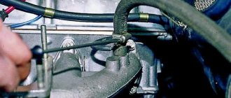
Where is the sensor located?
On VAZ cars of the 2109 family, the device in question is responsible for connecting and opening the contact group. The signal received by the sensor is converted into electrical form. Through the switch, it goes to the ignition coil, where a spark is already generated.
In carburetor cars, the device is installed on the ignition distributor under the protective shield. The sensor is fixed to a special plate using two bolts. Rivets are sometimes used. It all depends on the type of distributor.
Main symptoms of malfunctions
If this unit malfunctions, the following problems may occur in the “nine”:
- It is impossible to start the engine.
- Failures in the operation of internal combustion engines in different conditions. There are jerks and there is no smoothness.
- The engine is not able to idle.
- The engine stalls for unknown reasons.
- Reduced power of the power unit.
All of the above symptoms indicate a breakdown of the Hall sensor.
Troubleshooting
To determine a malfunction on a carburetor engine, you will need to know for sure that the device in question is the cause of all the problems.
Accordingly, it is necessary to check the sensor. This can be done in several ways:
- The most primitive method is to install a new element instead of the old device. If all symptoms disappear, then we can assume that the problem is solved. Otherwise, you need to look for a breakdown in other components of the ignition system.
- Using a tester, check the output voltage. If the device is working, the values will be in the range from 0.4 to 11 V.
- You can simulate the operation of the system. To do this, remove the block with three plugs, turn on the ignition, and close wires 3 and 6. The presence of a spark indicates that the device has failed.
If you don’t have a tester at hand, then you can use the following testing method:
- Connect the coil lead to the spark plug.
- The threaded part of the candle must be connected to the mass.
- Remove the carriage with the sensor and connect the connector.
- Turn on the ignition.
- Move the screwdriver close to the device. If a spark appears on the spark plug, everything works correctly.
If you determine that the regulator is broken, you will need to replace the sensor on the VAZ-2109.
Step-by-step process for replacing a device
Before you start replacing, prepare a standard set of tools.
Initially, remove the distributor from the additional equipment unit and you can start replacing:
- First of all, disconnect the battery (remove the negative terminal).
- Disconnect the armored wires from the distributor and remove the hose from the vacuum corrector.
- Pull out the gas cable and remove it.
- Unscrew the bracket nut that secures the wires. This element must be removed from the stud and moved to the side for convenience.
- Make a mark in the form of a straight line on the drive housing of auxiliary components and the distributor in order to set the correct ignition timing during assembly.
- Disconnect the block with wires.
- Remove the plug from the clutch housing and turn the flywheel with a screwdriver so that the piston of the first cylinder is in the TDC position.
- Unscrew the two fastening nuts and remove the distributor.
The sensor is replaced as follows:
- Unscrew the distributor cap.
- Remove the slider - to do this you need to pull it up a little.
- The next step is to remove the dust cover.
- Unscrew the fastening bolt and remove the plug.
- Remove the bolts securing the sensor support plate.
- After unscrewing the fixing bolts of the vacuum corrector and dismantling the locking ring, you need to remove the corrector and rod.
- Unclamp the clamp and remove the wires.
- Remove the mounting plate, unscrew the fixing bolts and replace the faulty sensor.
After completing the above steps to replace the sensor, the assembly of the structure is carried out in the reverse order.
To summarize the article, we note that we examined the general principle of operation of the Hall sensor on the VAZ-2109. Based on the above information, you will be able to diagnose problems with this unit in the car and, if necessary, replace the device. If you feel that you do not have enough experience in carrying out such work, then we recommend that you contact a specialist.
Malfunctions of the idle air regulator and its check
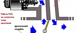
In cars equipped with an injector, a separate actuator (IAC), controlled by a controller, is responsible for engine idle speed and cold start. Although its design is simple and reliable, during the operation of the car the element may not work correctly or, like any other part, fail due to natural wear and tear. How to identify symptoms of a malfunction and check the idle air control in a garage is described in detail in this publication.
How does the regulator work?
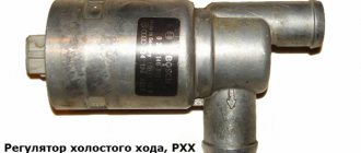
In everyday life, the IAC is often called a sensor, although in reality it is not one. The element is a stepper motor housed inside a non-separable housing. Only the spring-loaded rod with a cone-shaped tip protrudes outward. At the command of the ECU, the engine extends or retracts the rod to a certain distance.
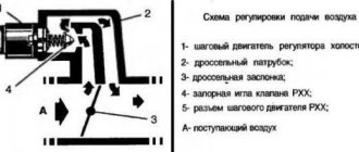
The idle speed sensor is located in the throttle valve block, the working cone is extended into a small cross-section bypass channel. Since the engine starts and idles without pressing the accelerator pedal, the mentioned channel supplies air to the cylinders when the throttle is closed. The task of the IAC is to regulate the amount of air flow, blocking part of the flow area with a cone.
To better understand the issue, it is worth presenting the operating principle of the idle speed sensor in the form of an algorithm:
- After the driver turns on the ignition, the controller activates the governor motor, forcing the idle air passage to open. The ECU calculates the opening amount using a temperature sensor - if the engine is cold, the rod will move back more.
- At the moment of startup, the injectors supply an enriched mixture to the cylinders. Then the amount of fuel is reduced so that the engine does not “suffocate” and stall. The speed is monitored by the control unit using a crankshaft position sensor.
- The volume of air entering through the IAC is taken into account by the mass air flow sensor located on the inlet pipe, while increased crankshaft speeds are maintained (1200–1500 rpm).
- Using the temperature sensor, the control unit “sees” that the engine is warming up and gradually reduces idle speed, giving the command to the IAC to cover the cross-section of the bypass channel. When the temperature reaches an acceptable value (60 °C or more), the regulator maintains the speed at 850 rpm.
Symptoms and causes of IAC malfunction
Signs of a malfunctioning idle speed sensor appear as follows:
- during a cold start, the crankshaft speed does not increase, which is why the engine runs unstable and tends to stall;
- there is a drop in the number of idle revolutions after a significant increase in the load on the generator - turning on headlights, electric heaters, and so on;
- the engine periodically stalls when any gear of the manual transmission is switched off (the symptom manifests itself while driving);
- The speed “floats” - it spontaneously increases and decreases.
Important point! There is a misconception that a regulator failure is necessarily accompanied by the inclusion of the Check Engine indicator on the dashboard. Since the element is an actuator, the light warning option is not provided in all cars.
If the car shows signs of IAC malfunction in the form of floating engine speed at idle, advanced diagnostics may be needed. A spontaneous change in the crankshaft rotation speed occurs for many reasons - failure of a sensor, air leaks, gas distribution malfunctions, and so on. It is better to start troubleshooting by checking the regulator.
IAC failure occurs for three main reasons:
- Open or poor contact in the power supply circuit. Simply put, there are problems with the wiring.
- Breakdown of the stepper motor due to natural wear and tear. In this case, only replacing the idle speed sensor will help.
- Contamination of the rod and cone with oil deposits.
There is a fourth reason - problems with the electronic control unit.
The problem is quite rare and is accompanied by additional symptoms - increased gas mileage, unstable operation in all modes, difficult starting, and the like. Oil deposits reach the rod thanks to secondary gases sent by the crankcase ventilation system for re-combustion. The more worn out the engine, the more deposits accumulate on the working cone. As a result, moving the rod becomes difficult; in advanced cases, the mechanism simply jams.
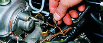
Sensor diagnostic methods
The easiest way to check that the idle speed sensor is working is to start the engine and remove the power connector from the block. When the element is in good condition, the speed will drop sharply and the engine will stop - when the power supply is turned off, the spring will push the cone forward and the cross-section of the bypass channel will completely close. If the engine operation remains the same or changes slightly, move on to other testing methods.
The next stage of diagnostics is measuring the supply voltage, performed in this order:
- Disconnect the IAC connector and turn on the ignition.
- Using a voltmeter, measure the voltage at the corresponding contacts of the removed connector (in VAZ cars these are terminals marked A and D).
- If there is no voltage or does not reach 12 volts, you need to look for a problem in the electrical wiring. Otherwise, proceed to diagnosing the regulator itself.
In VAZ cars, you can check the performance of the stepper electric motor without removing it from the car. Using a multimeter, measure the resistance between the following pairs of contacts: A - B, C - D (it should be 53 Ohms). Then measure other pairs - A - C, B - D, on a working regulator the device will show infinity.
Further checking of the idle speed sensor is carried out as follows:
- Disconnect the power supply, unscrew the mounting screws and remove the element from the throttle valve block.
- To prevent contamination of the rod, clean the cone and spring with a soft-bristled brush, using kerosene, diesel fuel, or better yet, carburetor cleaning fluid. Do not use acetone or solvents like 646 - they will destroy the plastic.
- Blow through the cleaned part and connect the connector.
- Place your finger on the rod and ask an assistant to turn on the ignition. The cone of a functioning regulator should move noticeably. If nothing happens, feel free to change the sensor.
Advice. If a strong oil deposit is detected on the working part of the IAC, it is highly advisable to perform the procedure for cleaning the throttle and bypass channel - a similar picture is likely to be observed there.
To install a new regulator, be sure to remove the negative terminal of the battery. After assembly and connection, the IAC controller is calibrated - you need to turn on the ignition and wait 15 seconds. If the battery is not disconnected, the ECU will skip the calibration step, which may cause the engine to run unstably.
Check the sensor for serviceability
Before installing the sensor on a VAZ-2107 car, it should be examined for serviceability. The best way to check the sensor is, of course, to check it with the car running, but you can also check it with a voltmeter. The sensor needs to be “ringed”. When the sensor contacts come into contact with the contacts, the voltmeter should emit sound signals; if there are none, then the sensor is faulty. You can check the functionality of the sensor in the same way using resistance. If the sensor is working, the arrows of the device are in motion. If not, they don't move.
Having secured the new sensor, we collect the whole story in reverse order.
VAZ-2017 is considered a classic of the Soviet and domestic automotive industry. Its history begins in 1982. Once upon a time, the “seven” was very popular. Even now, with the necessary care and proper maintenance, it fulfills its mission with honor. It's a shame if, because of such a miniature part as a Hall sensor, it ends up in the middle of the road. Always ensure that the Hall sensor is in good working order. And as a piece of advice, take this inexpensive but very important part with you in the car, otherwise you risk returning home at best by taxi.
Purpose and principle of operation of the Hall sensor
The Hall sensor takes its name from the name of the inventor who discovered the galvanomagnetic phenomenon in 1879. Its essence lies in the occurrence of a potential difference when a conductor is placed in a magnetic field, which causes the flow of direct electric current to it. The sensor uses the effect described above in the conditions of a conductor installed under voltage inside the device, which is affected by a magnetic field that crosses it across and creates an electromotive force.
The operating principle of the device is based on detecting the presence or absence of a magnetic field. When the induction force reaches a certain value, the sensor indicates the presence of a field. If the indicator is below the set value, the sensor indicates its absence. The sensitivity of the device is determined by the ability to detect a magnetic field of varying inductance, and can vary depending on the necessary requirements.
An automobile Hall sensor is designed to measure pulses, on the basis of which the electronics of the ignition control unit commands the formation of a spark at the required moment. Structurally, the device consists of the following parts:
- Permanent magnet.
- Steel screen with several cut holes.
- Semiconductor wafers.
A connector containing 3 terminals comes out of the sensor:
- The first output is connected to ground.
- The second is for connecting 6 V voltage.
- The third one supplies the converted pulse signal to the switch.
In most cases, the sensor is located on the distributor. It detects the moment a spark is given and is used instead of contacts. There is a digital modification of the sensor, which can be bipolar or unipolar. The first type is triggered when the polarity changes, and the second when a field appears.
Hall sensor for VAZ 2107
The Hall sensor is one of the main devices in the contactless ignition system of gasoline engines. If a problem occurs with this part, the operation of the engine is disrupted. In order to be able to diagnose the problem in a timely manner, it is important to know and understand how the Hall sensor (HL) works and, in particular, on the VAZ 2107, how to determine the malfunction and replace the device. All these points are worth dwelling on in more detail.
Purpose of the sensor
A number of electronic car systems are equipped with sensors that send a signal to the corresponding unit responsible for the operation of the power unit to change certain parameters. The contactless ignition system of the VAZ 2107 also has a device called a Hall sensor (HL). Its purpose is to determine the position angle of the crankshaft and camshaft of the power unit. The sensor is installed not only on modern, but also on old cars, for example, VAZ 2108/09. According to the readings of the element, current is supplied to the spark plugs.
Operating principle of the device
The operation of a DC is based on the effect of increasing voltage in the cross section of a conductor placed in a magnetic field. At the moment when a spark should appear, a change in the electromotive force occurs; a signal from the distributor is sent to the switch and spark plugs. If we consider the Hall sensor, which is used today in contactless ignition systems, it is a device for detecting changes in the magnetic field during camshaft operation. To trigger the element, a certain value of magnetic induction is required.
The sensor works as follows: there is a special crown-type plate on the distributor axis. Its special feature is the slots, the number of which corresponds to the number of engine cylinders. The sensor design also includes a permanent magnet. As soon as the ignition distributor shaft begins to rotate, the driven plate intersects with the sensor space, which leads to the generation of a pulse that is transmitted to the ignition coil. This impulse is converted and causes a spark to form on the spark plugs, as a result of which the air-fuel mixture is ignited.
As the engine speed increases, the frequency of pulses coming from the DC increases, which determines the normal operation of the power unit. Despite the fact that the phenomenon considered was discovered long before production cars appeared, it is nevertheless used in automotive production today. The sensor is a fairly reliable device, the breakdown of which does not occur very often.
Video: Hall sensor operation
The Hall sensor has three contacts:
Where is the DH on the VAZ 2107
If you are the owner of a VAZ “Seven” with contactless ignition, then it will not be superfluous to know where the Hall sensor is located. Finding the ignition distributor is not difficult, but the sensor itself is located under its cover. To access the DC, you need to remove two latches and remove the distributor cover, after which you can see the sensor itself.
Connection diagram
The Hall sensor has a direct connection with the switch and is connected according to the diagram shown in the figure.
The switch itself performs the following functions:
- amplifies the pulses to 12 V and transmits them to the ignition coil;
- receives a signal from the DC in the form of an impulse.
In simple words, the switch is a regular amplifier, which is designed in a similar way to an assembly based on field-effect transistors. Despite the simplicity of the circuit, the device is easier to purchase than to make yourself. The main thing is that the Hall sensor and the switch on the VAZ 2107 are correctly installed and connected. Otherwise, the sensor will not work properly.
Signs of a Hall sensor malfunction
Malfunctions of the Hall sensor can have various symptoms, based on which even an experienced technician is not always able to immediately identify the failure. The most typical symptoms of sensor failure are as follows:
- The engine starts poorly or does not start at all.
- When driving a car at high speeds, jerking occurs due to engine operation.
- Engine idling is characterized by jerks and interruptions.
- The engine stalls when driving.
The health of the Hall sensor can be checked in the following ways:
- By installing a known-good sensor in place of the one being tested. If the problems disappear when you start the engine, then the “original” sensor is faulty and needs to be repaired or replaced.
- Measurement of the sensor output voltage with a tester. A working device will show voltages ranging from 0.4 to 11 V.
- By creating an imitation of the sensor by removing the three-pin block from the distributor, connecting wires 3 and 6 of the switch output and turning on the ignition. A spark that appears indicates a breakdown of the sensor.
Why is a Hall sensor needed and how does it work?
The device of the contactless ignition system of the VAZ 2107 car has such an element called a Hall sensor. Its fundamental purpose is the ability to detect the angle of the crankshaft and camshaft of the power unit. The Hall sensor is not installed on injection models of sevens, it is installed only on carburetor ones.
According to the value of this device, voltage pulses are supplied to the spark plugs. The functioning of this element is based on increasing the voltage in the cross-section of a wire placed in a magnetic field. The element is connected by three terminals, two of which provide power supply (plus and minus), and the third contact is intended directly for supplying a signal. The device received this name due to a special effect that was identified by scientist Hall. In the distributor on the shaft there is a plate that is part of the control of the device controller.
When the motor operates, the metal in the slots alternately changes, and the magnet, which is located inside the controller, begins to be excited by oscillations of the magnetic field. In this case, the controller generates voltage pulses issued by the switch and supplied to the coil. The coil, in turn, raises the voltage to a high value and transports it one by one through armored wires to the spark plugs. Knowing the operating features, you need to deal with the malfunctions, but before that it is important to note that the Hall sensor on the VAZ 2107 is located in the distributor under the cover. To replace it, you will need to disassemble the distributor.
Basic sensor malfunctions
Any part on a car sooner or later begins to malfunction, and the Hall sensor is no exception, even though it has the simplest design. Its breakdown is detected by detecting the following defects:
- Inability to start the engine.
- Unstable and unstable operation of the motor.
- The occurrence of jerks.
- The engine begins to stall.
- The appearance of the detonation effect.
If the above symptoms appear, then there is no need to rush to change the Hall sensor, since similar phenomena can also occur due to other breakdowns of the ignition and fuel supply system. To verify that the device is faulty, you will need to perform a suitability test.
Check Features
The BSZ contactless ignition on the VAZ 2107 has a Hall sensor, the serviceability of which determines the normal operation of the internal combustion engine. If you suspect that it is faulty, then you need to check the Hall sensor. To do this, there are different ways on the basis of which one can draw a conclusion about the suitability of the element.
The following two methods are used to check an element:
- The simplest test method is to install a known-good element. If the signs of malfunctions immediately disappear, it means that the breakdown was detected correctly and successfully repaired. The disadvantage of this method is that you must first purchase a working element.
- Use a multimeter to check the voltage at the sensor output. The device switches on the voltage measurement mode, after which the value at the device output is measured. The value should be between 0.4 and 11 Volts, and if this is not the case, the element should be replaced.
- Simulation of device operation. The test diagram is as follows - the element terminal should be removed from the connector, and then turn on the ignition. Now we begin to simulate the operation of the Hall sensor, for which contacts 3 and 6 of the switch output are connected. If sparking occurs, the element must be replaced.
It is also important to check the serviceability of the terminal block to which the Hall element is connected. A multimeter set to voltage measurement mode is also used for this. One probe of the device needs to be thrown to ground, and the second one needs to check the readings on the red and green wires. The value of the readings should be equal to the voltage value on the battery.
If test manipulations show that the sensor needs to be replaced, then this action should be taken. Instructions on how to change the device on a VAZ 2107 are described below.
Replacing the Hall sensor on the seven
The device in question is small in size and is an integral part of the distributor. The process of replacing this part is not the most pleasant, since this will require removing the distributor or ignition distributor. Before you start work, you will need to purchase a new part (it is inexpensive, about 200 rubles), and also prepare the following tools:
- Wrench set to "13".
- Screwdriver with pliers.
- Hammer.
Replacing the Hall sensor on a VAZ 2107 begins with dismantling the distributor. Before this, you first need to use a marker to make marks on the distributor body and cylinder block, which will allow you to install the device in its place. This will eliminate the need to set the ignition after installing the distributor in place. To change the device, you will need to do the following:
- First you need to turn off the power to the car. To do this, remove the negative terminal from the battery.
- Remove the cover from the ignition distributor, as well as the vacuum hose.
- The device terminal is tilted away from the connector.
- Next, to dismantle the distributor, you will need to unscrew the bolt to “13”, and then remove the washer and remove the distributor.
- When disassembling the distributor, you will need to remove (knock out) the pin that holds the shaft with the oil slinger. To implement this action, you will need a suitable attachment, having first clamped the distributor in a vice.
- The plastic stopper with the washer is removed and the shaft is removed.
- To remove the sensor, you need to unscrew the two brass screws that secure the element, as well as the threaded steel connectors of the sensor.
- The vacuum corrector mount should be unscrewed, and then the device should be removed through the corresponding hole.
- The new element is installed in the reverse order of removal.
The replacement principle is not difficult, but the need to dismantle the distributor leads to the fact that it takes a lot of time. If the distributor is disassembled, it is recommended to immediately clean the shaft from carbon deposits by washing it in a solvent. After replacing the device, you can check the proper operation of the motor. Typically, the service life of the devices is quite long, and they rarely fail, but if this happens, you can replace it yourself without contacting a car service.
Hall sensor repair
The design of the Hall sensor is quite simple, and the device rarely fails. But when it breaks down, the car becomes immobilized, and the part requires urgent replacement. Since the sensor is quite expensive, especially for foreign cars, it makes sense to try to repair it yourself. For example, you can take a Volkswagen car device, which is installed on various models of cars from this automaker.
The most unreliable part of the sensor is the S441A logic element, which is the sensitive part of the device, which fails. The purpose of repair is to replace it. The procedure itself consists of the following steps:
- Purchasing a failed element or its equivalent.
2. Checking the part for functionality. For this purpose, an LED and a resistor (1 or 2 kOhm) are connected in series and attached to the “+” and “output” contacts. The current value should vary from 3 to 30 V, and the serviceability of the element is checked with a magnet: when exposed to it, the LED is activated.
3. Use a drill and a metal drill to make a hole in the center of the Hall sensor, cut the wires “flush” with a knife, and use a file to lay grooves from the hole made to the outputs of the remote wires.
4. Placing the active element in the completed window and checking its functionality. So, when the contacts are connected and the curtain passes through the slots, the LED should light up, and when the magnetic flux closes, it should go out.
5. If the circuit refuses to work, the element is turned over and tested again (the polarity of the location matters).
6. If the test was successful, the element leads are routed in the grooves of the housing. In the window itself, the wires that go to the connecting connector of the old sensor are soldered. Pay attention to the correct sequence of wires and their coincidence with the markings of the distributor connector (“+”, “0”, “-”).
7. Having completed soldering, check visually and with a tester for the absence of short circuits in the sensor. If the test is successful, seal the technological hole with heat-resistant glue.
8. The sensor is put in place and the circuit is checked for the absence of short circuits: none of the wires should contact the housing.
The sensors of many cars are restored in the same way. In addition to Volkswagen, devices for Daewoo, AUDI, Mitsubishi, etc. can be repaired, since their operating principle is the same in all cases.
Hall sensor replacement
Replacing the Hall sensor is a fairly simple operation that even a novice car enthusiast can perform independently. All actions are carried out in the following order:
- Dismantling the distributor.
- Remove the distributor cover and align the timing marks with the crankshaft mark.
- Fix the position of the distributor, then use a wrench to unscrew the fasteners.
- Remove the stoppers and clips.
- Remove the shaft from the distributor.
- Disconnect the terminals on the sensor and unscrew it.
- Carefully pull out the faulty device through the gap created when the regulator was pulled back.
- Installation of a new Hall sensor is carried out in the reverse order.
Replacement
If you are convinced that the problem is with the Hall sensor, then you can replace it yourself. This is not difficult and any motorist can handle it if desired. There is no point in overpaying the service station technicians; you can check it yourself and handle the replacement yourself.
Tools
You will need this screwdriver
Stages
It is advisable to carry out work in a well-lit room.
Correct connection of the block
- First of all, it is necessary to remove the distributor itself from the car and then unscrew the cover.
- Next, pull up a little and remove the slider.
- Remove the plastic cover.
- The plug is secured with a bolt and needs to be unscrewed.
- Let's take him out.
- The sensor plate is held on by bolts that need to be unscrewed.
- The vacuum corrector is fixed with bolts, we also unscrew them.
- Remove the retaining ring.
- We remove the traction and the corrector itself.
- To get the wires you need to move the clamps apart.
- Remove the support plate.
- Now all that remains is to unscrew a couple of bolts and remove the Hall sensor.
- We install a new one.
- Assembly work is performed in reverse order.
Important! If any signs of breakdown occur, do not delay repairs. Check the Hall controller immediately and replace it if necessary.
As you can see, everything is very, very simple. It is worth spending just an hour of your time to save several thousand rubles, which you will have to pay to the service station.
How to check the idle speed sensor
The idle speed sensor, which is also commonly called a regulator, performs the task of stabilizing the engine at idle speed. It is located near the sensor that controls the throttle position. The sensor is quite reliable, and its failure is very rare. However, such a problem can arise, and the driver should know how to check the idle speed sensor himself and make sure that problems in the improper operation of the engine of a stationary car are associated with its failure.
Video on how to replace a Hall sensor with your own hands
Welcome! Failure of such an important sensor will prevent the car from even starting. Injection systems have a crankshaft position sensor. Both sensors operate on the same principle. Failure of any other sensor will make it possible to start the car, but the engine will operate in emergency mode: a spark will not be given to any spark plug and the engine will simply spin at idle from the starter.
Note! You will need the following tools: a set of wrenches, screwdrivers, a hammer, and take a thin bit (an awl will do) and don’t forget the pliers!
Symptoms of a malfunctioning idle speed sensor
If the idle speed sensor fails, the driver will be notified of this by the Check Engine light (“Check engine”). However, if it lights up and the car has problems idling, this does not mean that the malfunction is definitely related to the sensor. Without checking the regulator, it is difficult to say for sure whether it is working or not.
We can identify a number of signs that are “beacons” that there are problems with the idle speed sensor:
- The car stalls at idle or its speed “floats”;
- In order for the engine to run smoothly, it requires significant warm-up time;
- When the gear lever is moved to neutral, the engine stalls.
The problems described above occur due to a lack or excess of air supplied to the engine when idling. However, it is not only the idle speed sensor that can cause such symptoms, which is why it needs to be diagnosed before choosing a new one to replace it.
How to check the idle speed sensor yourself
Checking the idle speed sensor yourself is quite simple, and the main problem is its preliminary dismantling. The first step is to determine where the idle speed sensor is located. Most often, the reference point when searching for it should be the throttle position sensor. If you cannot find the idle speed control during engine inspection, you should refer to the technical documentation for the specific car model.
When the idle speed sensor is removed from the engine, you can begin to diagnose it:
Connect the wires to the sensor;
- Place your finger on the adjuster needle;
- Ask an assistant to turn on the engine ignition;
- If, when starting the engine (at the moment the voltage reaches the sensor), you feel that the conical needle of the regulator has moved, then the sensor is working. When no shocks were detected, this indicates that the sensor has failed.
Another way to check the idle speed sensor is to diagnose the resistance of the throttle assembly. It is necessary to check the resistance of the windings using a multimeter. If the result is in the range from 50 to 55 Ohms, then the sensor is working.
Please note: Often drivers, after checking the above, conclude that the idle speed sensor is faulty, but this is not always the case. It is necessary to check not only the regulator itself, but also the circuit supplying control signals to it (supplying the sensor). Make sure that the voltage at the terminals of the connecting block when the ignition is started is at a level of 12 Volts. If it is less, the problem is most likely due to a dead battery. When there is no voltage at all, the control unit or wiring is to blame.
Removing the distributor from a VAZ-2107 car
To replace the sensor, we will need to completely remove the distributor from the car. Where is the distributor located on a VAZ-2107 car? It is located under the hood of the car, on the left in the direction of travel. Five high-voltage wires are connected to it.
Before doing this, pay attention to the location of the distributor relative to the body. Remember this position or make notes with chalk so that you don’t have to adjust the ignition later. First of all, the terminal is removed from the battery, then the wires attached to the ignition coil are disconnected, then the central high-voltage wire is disconnected. Using the tenth key, unscrew the bolts and remove the distributor from the VAZ-2107. Finally, remove the cover of the distributor itself.
It will be useful: Replacing the timing belt on a Chevrolet Cruze yourself: instructions with photos
Idle speed sensor dirty
Often the cause of improper operation of the idle air regulator is its contamination. In such a situation, you can replace the sensor (which is inexpensive) or clean it. Cleaning the idle speed sensor takes place in two stages:
- You need to moisten a cotton swab with a special product (for example, used to clean a carburetor) and use it to clean the sensor contacts. This must be done carefully so as not to damage them;
- The remaining parts of the regulator can be cleaned mechanically using the product indicated above. Moisten a toothbrush with it, for example, and carefully clean the needle, rod, spring, removing accumulated dirt.
Please note: When cleaning the idle speed sensor, it is recommended that you also clean the throttle body.