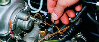
This device allows you to determine the angular position and speed of the crankshaft, and is also responsible for synchronizing the operation of the power unit and the control unit. It is located on the right front side of the engine.
By its design, this element is an inductive coil, inside of which a core and a magnet are located. It functions in conjunction with a toothed disk located on the crankshaft pulley.
The current is amplified and thermal compensation is introduced. The second group consists of sensors, the principle of which is obvious. It is essentially a membrane that is stored in a closed chamber that is supplied with pressure similar to the previous type of sensors. When pressure is applied, the membrane deforms and pushes or ejects the core. which is mechanically connected to it. Inductance is part of the oscillation circuit and its change due to different core insertion depths is reflected by changing the frequency generated by the circuit.
Thus, the output signal of the sensor will be an alternating voltage, the frequency of which varies depending on the pressure acting on the membrane. This group also includes Hall effect sensors. The magnet is attached to the diaphragm, and its magnetic field acting on the Hall element is changed by deflecting the diaphragm, which moves the magnet. As a result of changes in the magnetic field, the voltage output from the Hall element changes. proportional to the vacuum in the suction line.
The teeth of the disk passing near the end of the core provoke a change in the magnetic flux inside the DPKV. This leads to an alternating electric current occurring in the device. The resulting voltage, together with signals from other sensors, enters the ECU. After processing the received data, the control unit generates the parameters of the electrical pulses necessary for the operation of the ignition coils, as well as the injectors. Loss of performance of the DPKV leads to the cessation of operation of the ignition mechanism, and therefore the power plant.
Vacuum sensors are usually stored in an electronic unit and connected to the vacuum outlet of the suction line with a rubber or plastic hose. Another variable that affects ignition timing is engine temperature. It is measured by temperature dependent resistors that are placed in the coolant and divide its temperature. Resistance has a negative temperature coefficient, meaning that its value decreases as temperature increases. It forms part of a voltage divider whose output voltage is then proportional to the coolant temperature.
An ohmmeter is used to check the condition of the sensor. The resistance of the inductive coil should be 850-900 Ohms. For the device to perform its function normally, the teeth of the disk and the core of the element must be at a distance of 1-1.5 mm from each other.
To check the serviceability of the DPKV with higher accuracy, you should use the DST-2 device while cranking the engine with the starter.
This voltage is linearized accordingly to compensate. nonlinear dependence of a resistive sensor. The resistance housing is stored in a suitable enclosure that is protected from the environment. In addition to the crankshaft position and camshaft position sensors, load and engine temperature, some types of throttle and throttle switches are used. This switch provides the electronic unit with a throttle position signal corresponding to idle and full load.
Replacing the crankshaft position sensor
Today we will talk about how to replace the crankshaft position sensor with your own hands. According to experts, the crankshaft sensor is almost the only car sensor whose malfunction leads to the engine stopping.
Why is this happening? The main function of the crankshaft sensor is to synchronize the operation of the injectors or ignition system, and its malfunction automatically leads to a malfunction of the entire ignition and fuel supply system.
We must pay tribute to the fact that the crankshaft sensor does not fail very often. Typically, this happens for several reasons.
Reasons for failure of the crankshaft speed sensor
The reasons that lead to the need to replace the crankshaft sensor can occur at any time and anywhere on your route. Therefore, it would be absolutely useful to have a spare sensor in the trunk.
If you do not have the opportunity to replace the crankshaft sensor yourself, then any car service will do it for you in half an hour. The main thing you must remember and know: replacing the crankshaft speed sensor does not require disassembling the engine or removing the oil pan protection. You just need to remove the wheel.
So, the reasons for replacing the crankshaft sensor:
- mechanical damage to the crankshaft speed sensor housing, occurring for various reasons. In this case, the crankshaft sensor needs to be replaced;
- an interturn short circuit inside the winding, due to which the generation of pulses to the ECU fails at certain speeds. This is for pulse sensors, and they are the ones most common on current cars. Due to the difficulty of identifying this malfunction, when the speed limit occurs at 3-4 thousand, the optimal solution is to replace the crankshaft position sensor;
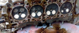
- Another malfunction that does not relate to the sensor itself, but affects its functionality, is the breaking off of the teeth of the drive ring. The reasons may be different, but the consequences are such that there is a loss of engine power, instability in engine operation and excessive fuel consumption.
DTOZH and DTV ZMZ 406 DIFFERENCE! CHOICE! — GAZ 31, 2.3 l., 1998 on DRIVE2
Let me start my story! So we have 4 types of sensors according to the numbers ZMZ 4061 42.38282 19.38283 40.5226ZMZ 405
4 40,5015
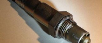
So these sensors are very similar, but still they are different. I won’t go into details about the characteristics and calibration of these sensors! I’ll tell you what they consist of and then you can decide which one to take! So the sensors 42.3828 and 19.3828 are identical from the outside They also have a black chip inside. It’s filled with some kind of compound, but not epoxy. It’s also strange that the thermistor itself is not in the upper part, but in the body where the thread is, which is somehow strange! Moreover, this is not just one sensor, but all 3 that I sawed.
Now the sensor is 40.5226, which turns out to be the most correct of all. Here are 2 new ones and the thermistor itself in the tip of the sensor and in the thermal paste, which is very good! Now together with the old one, which has been standing for a very long time, the coolest thing is that there are even inscriptions on the thermistor! These are K1019CHT1
The last sensor is from 405 of the 40.5015 motor, I’ll tell you right away it’s not worth putting it on 406. The RXX goes crazy and apparently adjusts the parameters of the other thermistor in steps! WITHOUT CALIBRATION IN THE FIRMWARE DO NOT INSTALL A thermistor of a different shape.
CONCLUSION FOR YOURSELF LOOK FOR SENSOR 40.5226 FOR REPLACEMENT IF ANYTHING!
So what is this recording for anyway? ALL THIS IS TO GO TO JANUARY 5.1.2-41 DAD+DTV
www.drive2.ru
Do-it-yourself crankshaft sensor replacement technology
The first thing you need to do if there are signs of a sensor malfunction is to diagnose it. After first reading the instructions about the design of the sensor of your model.
The crankshaft sensor is checked with a conventional ohmmeter or a tester in ohmmeter mode. The instructions for the sensor should indicate its operating resistance. It is this figure that you need to focus on when measuring resistance. If the resistance is lower than that specified in the manual for the type of sensor, then replacement of the crankshaft sensor is clearly necessary.
Replacing the crankshaft position sensor requires special attention to the clearance distance between the sensor core and the timing disk. Each type of sensor and engine model has its own, so again we head to the instructions specifically for your car.
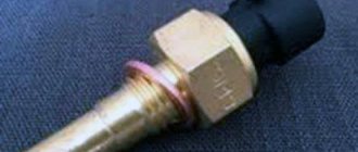
antifreeze temperature sensor | ZMZ engines
The topic of the article is DTOZH ZMZ 406, 405 and temperature sensor ZMZ 409. Everything seems simple: the part is cheap, and replacement takes 5 minutes, but “you’re not in the right place here,” our spare parts won’t let you get bored. People a long time ago categorized these sensors by color, completely ignoring the fact that different sensor manufacturers have different colors for the same sensor.
DTOZH ZMZ 406, 405 – rake or work experience
I encountered these “petty” sensors under the following circumstances. A gazelle arrived, which “lit the candles” in the morning. I'm in a cavalry attack, dashingly, I set the broken timing belt according to the marks, change the spark plugs, check the engine - the engine runs much better when hot. And you can’t start the car in the morning. The candles are wet as frogs. A diagnostician I know gives advice: go to the store and immediately take 4-5 DTOZH ZMZ 406, 405 and then, according to the joke... we calmly go down the mountain and have the whole herd. With EACH sensor I had to connect a diagnostic computer and see what it wanted to show. The readings at the time of launch were from -20 to +30 (it’s the middle of summer). Naturally, the brains, having received such information, began to “give gasoline to warm up” and everything flooded. Of the four DTOZH ZMZ 406, only one was more or less adequate.
Theory
antifreeze temperature sensors
The main ambush for the client and the diagnostician lies in the following. On engines E-0, E-2, sensors come from the factory with a “square” connector, on E-3, E-4 with an oval connector. But that is not all. On E-0 and E-2, these sensors are also non-interchangeable and differ according to the type of ECU. But most importantly, DTOZH ZMZ 406, 405, 409 should be from Russian factories or brand manufacturers (Bosch). Relatively high-quality products are produced by two Kaluga and Autotrade. Sensors of glamorous pink color from Arzamas are “not that”. Sensors of all colors of the rainbow from the Middle Kingdom, “not at all.” What should be included according to the factory documentation:
- EURO-0, ECU MIKAS7.1 - DTOZH 19.3828, 42.3828 or 40.5226. The operating principle is a thermal diode. The sensor housing is black.
- EURO-2, ECU MIKAS-11\VS8, SOATE - DTOZH 40.5215. Thermistor. The sensor housing is gray.
- EURO-3, EURO-4. Catalog number 40904.3828000. DTOZH 234.3828. Oval connector.
Temperature sensor ZMZ 409
I would like to dwell in more detail on the DTOZH for the E-3 and E-4 engines. Unlike sensors E-0, E-2, in this case there is a good alternative to Russian sensors. Sensors from imported manufacturers (Bosch, Febi, Vernet). Their big advantage is the following. All temperature sensors have a certain time delay in readings. For good imported analogues, this parameter is almost two times lower. And if the engine does not have a viscous coupling, but fans, then this parameter becomes very, very important. Unfortunately, I don’t know any imported analogues, DTOZH ZMZ 406 for E-0, E-2. I had to get rid of it as soon as possible. In particular, I took several sensors, gave them to a turner at the factory, and he reduced the wall thickness to the thermoelement as much as possible. This certainly has an effect.
Important. After the temperature sensor ZMZ 409, 405 (especially E-3, E-4) has been replaced, it is highly advisable to carry out the “reset and initialize the ECU” procedure. This can be done either using the on-board computer, or by connecting diagnostic equipment.
zmz-fr.ru
Checking the timing sensor
Turn off the ignition and disconnect the negative terminal of the battery.
Using a thin screwdriver or awl, remove the spring clamp of the block.
Disconnect the synchronization sensor connector.
We connect an ohmmeter to the central and one side terminal.
We measure the resistance of the sensor winding, which should be in the range of 700-900 Ohms.
To further check the serviceability of the sensor, remove it from the engine.
You can verify the functionality of the sensor by connecting a voltmeter to its terminals.
We quickly bring the metal rod to the sensor core - if it is working properly, voltage surges are observed on the device.
We replace the faulty sensor.
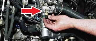
Removing the timing sensor
Using a 10mm wrench, unscrew the bolt securing the sensor to the engine block
Remove the sensor from the hole.
By bending the sensor wire fastening clamps located on the intake manifold and cylinder block, pull the wire along with the connector downwards
Install the sensor in reverse order.
After installing the sensor, use a set of feeler gauges to check the gap between its rod and the teeth of the synchronization disk.
The crankshaft of an internal combustion engine is a crankshaft element that serves to convert the reciprocating motion of the pistons into rotational motion. On injection cars with an ECM, a so-called crankshaft position sensor (CPS, synchronization sensor, crankshaft sensor, TDC sensor, sometimes called a phase sensor in everyday life) is used, which is necessary for precise synchronization of the operation of the ignition system and the power system.
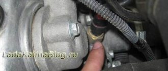
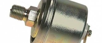
Oil pressure sensor Gazelle
This device is part of the oil supply control system. The alarm instantly reacts to even a slight change in oil pressure using a membrane installed in it and immediately informs the driver about this by turning on a warning light on the instrument panel.
The higher the engine speed, the faster the required number of pulses will be achieved, so that the ignition advance increases with increasing speed. Engine load, i.e. function, can be implemented by moving the start of the reading to the signal from the vacuum sensor. This speeds up the rotational response and the resulting prediction increases or decreases.
The block diagram of this type of ignition is shown in the figure. It is clear that in this way we can realize courses very similar to those achieved by mechanical regulators. However, they have many advantages over them. They have no hysteresis, meaning that the rate is the same for increasing and decreasing speed. Aging and material wear are not applied, so the course entered into the control unit does not change over time, and the course does not need to be regularly checked and adjusted in advance.
When the engine starts, there is no oil pressure inside the system, so the indicator contacts are closed and it lights up. When the engine is running, the oil pressure increases, which is captured by the sensor membrane, and the warning light turns off.
When the pressure drops below the minimum level again, the membrane equalizes, the contacts close, and the indicator lights up. During normal operation of the power plant, it should not light up. If the indicator lamp lights up while the machine is running, this indicates that the oil pressure is too low.
It is also important that the purpose of the process can be easily changed by changing component values or by connecting control unit circuits. Areas of characteristics that can be realized by this. this corresponds approximately to the right side of the figure. On the left side of this figure there is an array of characteristics similar to one engine. he is really needed. Similar, or at least similar forms, can perform functions according to the equation. To conduct such signals, it is necessary to use only digital data processing, that is, signals from sensors of the corresponding parameters.
To check the device, you need to connect to it a short rubber hose, at the other end of which there is a special adapter, the diameter of which matches the outlet of the pump. Then you need to create artificial pressure with a supercharger. The coincidence of the device readings with the characteristics of the sensor indicates the serviceability of the device.
A simplified block diagram of such a system is shown in FIG. They are then fed to a computer, which calculates the maximum current value for specific engine operating conditions. The computer can be solved in two ways. Therefore, such systems are also called memory systems. Each memory location stores appropriate preset values, usually depending on engine speed and load. Memory addresses are then selected according to the sensor signals of these parameters. The influence of other parameters can then be expressed by adjusting the overrun target values, either in stages or continuously.
You can check the alarm in another way. To do this, you need to put it in a saturated soap solution for 10-15 seconds, then remove it and connect it to the pumping device. Having done this, create pressure in the device using a pump. Soap bubbles appearing on folded joints indicate a sensor malfunction.
512 preliminary values are programmed in the semiconductor memory of the control unit. The engine speed is measured by a sensor relative to the flywheel gear gear. The engine load is determined by a vacuum sensor located in the control unit and a hose connected to the intake manifold opening. Each half stroke is selected from one of 512 programmed values in accordance with the speed and vacuum sensor signals. The action is synchronized with the top dead end signal from a sensor located opposite the crankshaft pulley.
If the detector is determined to be inoperative, it should be replaced. This is done in the following order:
- Disconnect the cable going to the instrument panel from the device.
- Unscrew the sensor using a wrench. If the thread is broken, you need to remove it with pliers.
- Remove the element from the hole.
After removing the part, you need to inspect the aluminum seal, because if it is faulty, oil will leak out from under it. A seal that is not working should be replaced. If it is working properly, the reason lies in the sensor itself, instead of which you need to install a new one. Installation is carried out in the opposite order of removal. In this case, you should definitely check whether the new device and the control indicator are well connected to each other.
Two two-position switches can be connected to the control unit, such as a warm cold engine and a throttle position switch. The control unit also includes an ignition end stage that operates to regulate the switching angle. The output of the output stage is connected to the ignition coil and from it to the hub distributor.
Secondly, the security of the program is microprocessor controlled computers. It is an integrated circuit whose function can be changed by entering the appropriate program. In this case, it is a procedure for calculating the forecast, that is, a function with a sequence according to the severity of the input parameters. This component is more or less universal, and its function is not determined solely by the external connection, as in the technical solution, but it is decisively dependent on the control program in which the microprocessor instructions are given.
Crankshaft sensor functions
As already mentioned, one of the obvious signs of DPKV problems is a complete engine stop. This happens as a result of the fact that malfunctions in its operation do not allow the power system to supply fuel in a timely manner, and the ignition system is not capable of igniting the fuel-air mixture at a given moment. Now let's look at why this happens.
The crankshaft sensor sends signals to the ECU indicating the position of the crankshaft at a certain moment, and also reports the direction of rotation of the shaft and indicates the rotation speed. Please note that on different cars, both the device itself and some functions of the DPKV may differ. This depends on the type of element installed. Devices can be:
Gazelle camshaft sensor (DPRV)
The task of this element is to determine the TDC of the piston of the 1st cylinder during the compression stroke. The device is located on the cylinder head near the 4th cylinder (on the left side of the head).
The basis of the operation of the DPRV is the Hall effect. When a metal plate fixed on the camshaft passes near the end of the element, the magnetic flux inside it changes, which, by analogy with DPKV, contributes to the emergence of an electrical signal. Then it is amplified, after which the signal enters the ECU.
The switch is mounted on the suction line at the throttle valve point and is controlled by its shaft. As the throttle rotates, the switch ball moves around the contacts. There is always one of these contacts in the idle or full load positions. Information from the commutator is used to control the progression of these engine operating modes. One of the possible options.
For newer ignitions, switching angle adjustment is used, i.e. ignition coil filling time. For this purpose, information about the battery voltage is supplied to the control unit, which is one of the parameters according to which the primary coil current is initiated. According to the sensor signal, the ignition advance angle is set in accordance with the engine prediction characteristic, which is programmed in the control unit for the corresponding engine. Its reaction depends on the fit of the form. circuits and the meanings of their components.
The control unit, having processed the signals received from the DPKV and DPRV, ensures synchronization of the fuel supply by injectors to all cylinders of the internal combustion engine during the compression stroke.
If the DPRV or signaling circuits lose their functionality, the ECU's backup mode is activated, in which fuel is supplied to all cylinders of the power unit simultaneously.
The appropriate choice will allow you to achieve the desired promotion characteristics in two ways. The first implements the functional relationship between the promotion parameters and the engine. It is assumed that the expression is a sum of functions, each of which depends on one parameter.
The second method, which has a more realistic effect on the combustion behavior of the mixture, assumes that the value of the maximum current is given by one function of several variables. According to the equation, circuits with analog processing of signals from sensors can be used. The desired course is achieved by changing the values of the circuit components. For a number of reasons, such solutions have not been expanded. Much better is digital signal processing. When the preset number is reached, a trigger pulse is generated.
You can check the serviceability of the DPRV with the engine running using the DST-2 device.
Crankshaft position sensor: signs of malfunction and checking the DPKV
If the cause of the problem is the crankshaft sensor, symptoms of a malfunction may be as follows:
- a cold or warm engine will not start;
- detonation occurs during operation under load;
- idle speed fluctuates;
- Engine power decreases, dynamics disappear;
- The speed jumps while driving, the speed changes randomly, etc.
Please note that these symptoms may also appear as a result of other malfunctions. For this reason, before starting manipulations with DPKV, other possible problems should be excluded. It should also be added that malfunctions of the crankshaft sensor may not occur all the time. In other words, unstable operation of the internal combustion engine or problems with starting may not always appear, although the “check” lights up. In this situation, it is recommended to perform computer diagnostics of the car engine to more accurately determine the cause.
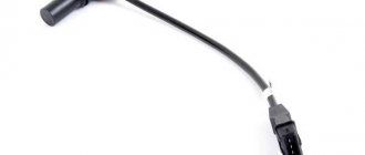
You can also check the crankshaft position sensor yourself. For such a test, there are several available methods that allow you to determine the performance of the element with relative accuracy. The device is enclosed in a plastic case, which is usually mounted on a bracket at the location of the generator drive pulley. A longer wire can also be connected to the element. The use of such a wire is due to the fact that the installation site of the DPKV is quite remote.
If a visual inspection reveals nothing, then the synchronization sensor will need to be removed, after which you can proceed to the test. The element should be inspected again, which helps determine damage to the housing, core, and terminal block. It should be added that quite often, after simply cleaning the contacts and cores from dirt, the DPKV begins to work normally.
Temperature sensor GAZ-3110,3302 dv.ZMZ-406 coolant RICOR 405226 — 2 reviews
Print Home Spare parts for our machines and tractors
65
1
Applicable: GAZ, UAZ In stock
Available for order - >10 pcs. Data updated: 08/26/2019 at 08:30
Characteristics
Report an inaccuracy in the product description
Product reviews
Where is it used?
- Passenger cars / GAZ / GAZ-2217 (Sable) 1 drawing
- Passenger cars / UAZ / UAZ-31519 6 drawings
- Passenger cars / GAZ / GAZ-3111 2 drawings
Certificates
Reviews
All reviews are included in the competition - competition rules.
- There are no reviews for this product yet.
Write a review
Availability of goods in warehouses and stores, as well as the price of goods is indicated as of 08/26/2019 08:30.
Prices and availability of goods in all stores and warehouses are updated once an hour. If there is a sufficient quantity of goods in the store you need, you can buy it without pre-ordering.
Internet price - valid when ordering on the website or through a call center operator by calling 8-800-600-69-66. Subject to sufficient quantity of goods at the time of order.
Price in stores - the retail price of the product in stores without pre-order.
The period for moving goods from a remote warehouse to the warehouse of an online store.
The parts data presented on this page is for informational purposes only.
www.avtoall.ru