Like most cars with 4-cylinder engines, the Lacetti has 2 camshafts - one exhaust, one intake. The main function of camshafts is to control the valve group of the power unit. With the help of cams on the camshaft, the valves of a particular cylinder are opened and closed. In many ways, the operation of this particular unit ensures the smooth and uninterrupted operation of the internal combustion engine and its achievement of the planned power.
Replacing the Lacetti camshaft position sensor
If your car's engine exhibits the symptoms described below, then the camshaft position sensor most likely needs to be replaced.
This article will help you replace it in 20 minutes. So, if there is a suspicion that the Lacetti camshaft sensor is faulty and the following symptoms are observed:
1. The electronic engine control unit operates in emergency mode
2. Fuel consumption has increased
3. Sometimes the camshaft position sensor error check light comes on or stays on constantly.
4. The engine does not start easily. When cold, the engine starts only the second time
5. Engine power has decreased
6. RPM fluctuates when coasting
then the camshaft sensor needs to be replaced. But before that, be sure to check the wiring of the DPRV
What is a camshaft position sensor used for and how does it work?
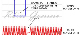
The ECU uses the sensor signal to coordinate fuel injection processes in accordance with the operating order of the cylinders. The operating principle of the sensor is based on the Hall effect. The camshaft position sensor responds to the passage of a protrusion made on the end of the camshaft pulley to determine the position of the piston of the first cylinder during the power stroke. Depending on the angular position of the shaft, the sensor outputs rectangular voltage pulses of different levels to the control unit.
Working principle of the camshaft position sensor
Based on the signals from the crankshaft and camshaft position sensors, the control unit sets the ignition timing and the cylinder into which fuel should be supplied. If the phase sensor fails, the ECU goes into emergency operation mode.
Location of the knock sensor
The sensor is mounted on an aluminum or cast iron cylinder block in the area between the second and third cylinders. This is the hottest place in the block, and the shortest distance to two cylinders at once. The choice of the location where the knock sensor is located is not accidental; it is in the hottest combustion chamber that detonation will begin to develop, while in the remaining cylinders the conditions have only approached the permissible limit. The sensor mounting location always has a smooth, flat surface to eliminate possible acoustic resistance or distortion of sound waves. The body of the device is always secured with a pin connection, guaranteeing a full, tight fit to the installation site.
Replacing the Lacetti camshaft sensor
Removing the decorative trim of the engine
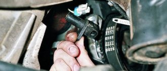
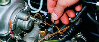
Next, disconnect the electrical connector from the sensor.
But I advise you not to do this. Because we will remove the sensor through the top and the wires will help us with this. The wires will also hold the sensor so that it does not fall down when we unscrew the bolts that secure it.
Next, remove the air filter housing. To do this, unscrew the collar securing the corrugation with a screwdriver and disconnect the corrugation from the air filter housing.
Then we tighten two bolts (one with a 10 mm head, and the other with a 12 mm head) securing the housing and remove the housing.
The next step is to remove the upper timing case. It is secured with three bolts.
A 10 mm socket wrench works well for this.
Next, move the cooling system hose towards the engine, unfasten the casing and remove it.
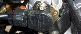
We see the camshaft sensor and two bolts securing it.
Next we have two options. The fact is that the bolts are in a very inconvenient place and the support bracket prevents them from being unscrewed normally.
Therefore, you need to decide how to proceed:
- We hang the engine and unscrew the support bracket. After this, we quite easily unscrew the sensor mounting bolts.
- Using sleight of hand and a suitable tool, unscrew the sensor mounting bolts. It will be difficult, but possible.
Personally, I always choose the second option.
To do this, the first and mandatory action will be to seal all the voids under the sensor with a rag, so that accidentally dropped bolts or keys do not cause us trouble. Since to get them out you will have to remove the lower timing case with all that it entails.
Attention! The rag must be absolutely clean so as not to contaminate the timing belt.
Next, use our 10 mm socket wrench to unscrew the top bolt.
If suddenly your key is a little thicker and does not fit a little to fit it onto the bolt head, then engage fifth gear and slightly rock the car back and forth. This is necessary so that the camshaft pulleys rotate and the groove, and not the pulley tooth, hits the key. This will help you win a little more space and perhaps it will be enough for you.
If you do not have miniature fingers, then unscrew the bolt only a couple of turns. And then we hook it with soft wire
This will allow you to easily unscrew the bolt completely and pull it out by the wire. This is a 100% guarantee that it will not fall anywhere.
Using the same wire, it is easy to install it to screw in the new sensor, since fingers cannot fit in there.
Unscrew both bolts in this way and remove the camshaft sensor
Unplug it from the connector and throw it away.
Note: Pay attention to the condition of the wires. They dry out and begin to crack, which leads to short circuits! This problem must be eliminated!
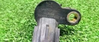
We take a new original camshaft position sensor. Exactly original! Don't skimp on DPRV, DBP and crankcase ventilation valve. Their cheap counterparts don't work.
The original sensor costs 1000 UAH (40 usd or 2540 rubles). The analogue is three times cheaper, but at best it will blow your mind. And in the worst case, the car will be burned.
Check that the plate is straight and not bent
Platform control on KAMAZ-5511
To turn on the PTO on the KAMAZ5511 dump truck, you will need to move the lever on switch 6 to the “On” position; to do this, press the lock button, which is located on the body of this switch. In this case, the clutch must be disengaged. The signal lamp 5 will light up. And the electric current through fuse 8 will flow to the winding of the electromagnet on pneumatic valve 4.3, its core will move and open the valve. At the same time, air from the receiver will begin to flow into the cavity of the 3.3 KOM pneumatic chamber, and as soon as the clutch is engaged, pump 10 (oil) begins to work.
From oil tank 12, oil will flow through a pump through a pipeline into control valve 2 and then to drain back into the oil tank. Such oil circulation helps to warm it up in cold weather, which improves the operating conditions of the hydraulic system of the tipping mechanism.
Instructions on how to lift the body of a KamAZ 5511
To raise the 5511 dump truck platform, you need to press switch button 7 “Lift” to the “On” position. From the switch, the electric current will flow to the windings of electro-pneumatic valves number 4.1 and 4.2, their cores, having moved, open these valves. From the receiver, air is supplied to pneumatic chambers number 3.1 and 3.2 on the control valve. From the control valve, oil will flow through pipelines into hydraulic cylinder 1. Under the influence of oil pressure, all links of the hydraulic cylinder will sequentially extend, thereby lifting the platform. When the platform is raised, the hydraulic cylinder gradually tilts, and when the lift angle reaches 60°, the hydraulic cylinder body presses the adjusting screw in the platform lift limit valve (number 13 in the diagram below), the oil goes through the valve to drain. At the same time, the platform will stop rising.
Now you understand how to raise the body shock absorber; the cost of incorrectly adjusting the angle of inclination is, at a minimum, a breakdown of the hydraulic cylinder.
To stop the 5511 dump truck platform in its intermediate position, when lifting or lowering, it is necessary to move the “Lifting” or “Lowering” switch key to the “Off” position. At the same time, the electro-pneumatic valves are turned off, the air leaves the working cavities of the diaphragm chambers number 3.1 and 3.2. The hydraulic cylinder line closes, the cavity of the control valve begins to communicate with the drain line, and the oil goes to drain.
To lower the dump truck body, you need to move the switch key 7 to the “On” position. The current will flow to the winding of valve 4.1, its core, moving, will open the valve. The air will enter pneumatic chamber 3.1, in the control valve. From the hydraulic cylinder, the oil will flow through the tap into the tank. After the platform is completely lowered, you should move the key on switch 7 to the “Off” position. The lever on switch 6 is also set in the neutral position, while at the same time depressing the clutch pedal. The oil pump will stop working. It should be noted that the KAMAZ-5511 body can be lowered both when the oil pump is running and when the pump is already turned off.
- Absolutely legal (Article 12.2);
- Hides from photo and video recording;
- Suitable for all cars;
- Works through the cigarette lighter connector;
- Does not cause interference to radios and cell phones.
A small upgrade. Body lift valves, replacing old ones with euro ones
The body does not rise. What to do?
Everyday life of KAMAZ drivers: Lifting the body and the sound of the v8 engine
Body lift limit valve. Principle of operation. Repair. Service.
KAMAZ body lift hydraulic distributor repair
How did I make the body rise at idle and not fall? Kamaz 5511
Kamaz Review of the shaker! To the common people (shaking)
Oil pressure dropped to almost 0
Kamaz 6520 dump truck diagnostics using Avtoas-Cargo program
Chevrolet Lacetti SW cherry › Logbook › replacing the camshaft sensor Lacetti 1.6
Symptoms: 1. The Jackie Chan check light comes on, sometimes it goes out, then it lights up again. After diagnostics, we get the following: the camshaft position sensor is low.
2. The car sometimes does not start the first time. 3. Some others experience increased consumption and decreased engine power, but this did not happen to me.
We run, hurry to the store for a new sensor. A General Motors original is a must. 96253544
. I took it from Exist for 1232 rubles.
I won’t write, like many others, that the replacement took 10 minutes with smoke breaks, it took at least an hour, since I did everything for the first time. And yes, you will need slightly sophisticated tools, because you can’t get into it with a regular ratchet with heads. Anticipating this, I borrowed sets of tools from friends to use.
1. Remove the decorative engine cover
2. Remove the air filter housing
3. Unscrew the upper front timing belt cover. It is held on by 3 bolts.
4. We see 2 bolt heads between the pulleys; they secure our sensor.
5. Disconnect the wiring harness block from the camshaft position sensor (there is a metal bracket, you need to press it and the sensor will be removed).
6. Now we proceed to unscrew the camshaft sensor mounting bolts. I used a small ratchet, a 10 mm head, a thin-walled one, a flexible spring shaft and a rotary shaft.
To prevent the bolts from falling, I stuffed a cloth there.
7. Remove the old sensor and install a new one
8. Reassemble everything in reverse order. 9. Start up, enjoy))
Issue price: 1,232 ₽ Mileage: 103,500 km
see also
Comments 33
The problem is the same. -250000 mileage, changed sensor Original number 96253544 GM
-262000 mileage check again. I installed a new one. Purchased at Exist for RUB 1,199. I ordered Daewoo. GM has arrived. Old sensor does not magnetize New magnetite
You need to look at the wiring to the sensor, it may cause a check to appear.
The problem is the same. -250000 mileage, changed sensor Original number 96253544 GM
-262000 mileage check again. I installed a new one. Purchased at Exist for RUB 1,199. I ordered Daewoo. GM has arrived. Old sensor does not magnetize New magnetite
also tempered Daewoo, orig GM was gone for 2 years
Error 341 pops up periodically! It’s easier to catch it in hot weather; as the temperature drops, the error hasn’t popped up for a month, but again, sometimes there’s a bad start. In general, I definitely don’t recommend taking it! While I’m skating like this, when it starts to die I’ll only take the original one.
I already bought Delphi. I can’t make a blog entry
Were there any numbers on the original sensor?
Who knows now?!
how long did the sensor last?
9 years and 103 thousand km
great fellow countrymen. can anyone tell me. error 0342. changed the sensor, it didn’t help. I replaced the wiring to the ECU, it didn’t help. I checked the voltage coming to the sensor contacts on 1 contact, the norm is 12.5 V, on the second I don’t understand the idea, this is a minus, but when you check with a tester, it shows 2-3 V ( should be 0), for 3 there should be about 5 V, shows 0.2 V. According to the diagram, I checked for 1 contact, the wire goes from 66 contacts of the computer with a connection to the fuse block. From 3 contacts to 22 of the ECU, but 2 goes to 17 with a connection to the connector that is located behind the fuse box, although according to the diagram it should be in a straight line from 17 to 2 sensor contacts. The car starts only at + temperature.
Principle of operation
Engine oil test 0W40 API SLLUKOIL SYNTHETIC - reviews and expert testNORDIX PLATINUMADDINOL ULTRA LIGHT - reviews and expert testMOBIL SUPER SYN 0w40 - reviews and expert testSHELL HELIX ULTRA - expert reviews and testLUXOIL BRILLTEXBP VISCO 7000 - review
The mechanism that lifts the platform is hydraulic. It consists of a power take-off box (abbreviated PTO), an oil pump, a hydraulic distributor, a hydraulic cylinder, a valve that limits the rise of the platform, a pneumatic block, an oil tank with a filter and a whole system of hydraulic and pneumatic wires.
To turn on the hydraulic systems of the platform tilting mechanism, you need to turn on the clutch, then turn on the electromagnet “A” on the pneumatic block (look at the diagram of the mechanism components just above), which controls the power take-off. The air, in this case, enters the pneumatic cylinder 4, which turns on the PTO 3. As soon as the clutch is engaged, the oil pump starts working, from tank 1 the oil flows to the hydraulic distributor 7, from which it goes to drain.
To raise the platform, you need to turn on the electromagnet “B”, which controls the hydraulic distributor section. From the pneumatic system, air enters the pneumatic cylinder 6 on the hydraulic distributor 7 and moves its spool to the left extreme position. In this case, the drain cavity in the hydraulic distributor is closed, and the pressure cavity is connected to the line of the hydraulic cylinder 10. In the event of a dangerous increase in pressure inside the pressure line, the safety valve 11 should operate.
To stop raising the platform, it will be necessary to turn off the electromagnet “B”, which controls the hydraulic distributor section. At the same time, the cavity of the pneumatic cylinder of the hydraulic distributor will connect to the atmosphere, and the spring will return the spool to its neutral position. The hydraulic cylinder line is blocked and the platform stops in its raised state. The discharge cavity of the hydraulic cylinder is connected to the drain, and the oil coming from the operating pump is drained into the oil tank.
To lower the platform, you need to turn on the electromagnet “B”. Then air from the pneumatic system enters another cavity of the pneumatic cylinder of the hydraulic distributor and moves its spool to the right extreme position, while the hydraulic cylinder line is connected to the drain, and the platform begins to lower. As soon as the platform has finished lowering, you need to turn off the electromagnets (all without exception), and the pneumatic distributor handles must be set to its original position. And when disabling the PTO, you must disengage the clutch again.
Chevrolet Lacetti camshaft position sensor error, sensor wiring repair
The service life of the camshaft position sensor (DPRV or Hall sensor) of the Chevrolet Lacetti is not regulated in any way. But as practice shows, the DPRV begins to malfunction closer to 100,000 (km) mileage .
warning light that the camshaft position sensor is not working properly . When decoding the emergency code, error 0342 : “Low level of camshaft timing sensor signal.”
Additionally, incorrect operation of the camshaft sensor can be diagnosed by the following symptoms:
- The car doesn't start the first time
- Fuel consumption has increased noticeably
- Engine speed started to fluctuate
Please note that replacing the Hall sensor must be preceded by diagnostics . It often happens that the DPRV itself is in completely good condition, but the problem lies in the current-carrying wiring. In this case, installing a new sensor will not help. The Hall sensor error can only be eliminated by repairing the wiring.
Examples of vehicles with P0341
- An Acura service bulletin (TSB) describes an issue where a stuck or dirty VTC (variable valve timing) control solenoid valve can cause trouble code P0341. The bulletin recommends updating the ECU software and replacing the VTC solenoid valve if necessary.
- The service bulletin for 2003 Jaguar V6 models mentions checking the spark plug resistance and replacing the spark plug along with the coil if the spark plug resistance is too low.
- A technical service bulletin for late 90's Saturn vehicles describes a problem where improper resistance in the ignition wires can cause a P0341 code.
- For a 2010 Chrysler pickup equipped with a Cummins diesel engine, in case of P0341 it is recommended to reflash the ECU.
- In some 2003-2010 Honda Accord, Civic, CR-V and Element 4-cylinder engines, a stretched timing chain causes the Check Engine Light (MIL) to come on with code P0341.
Previous post Error P0301 - misfire detected in the first cylinder
Next Post Error P0400 - Exhaust Gas Recirculation System Malfunction
Step-by-step instructions on how to restore normal operation of the Chevrolet Lacetti DPRV
As mentioned above, repairing the camshaft sensor should begin with diagnosing its technical condition. First of all, you need to ring the Hall sensor wiring itself. For diagnostics, the technician will need a car multimeter. Without preliminary diagnosis, it is better not to carry out any manipulations with the DPRV !
- We stop and turn off the car. There is no need to disconnect power from the battery.
- Remove the camshaft sensor wiring harness. To remove the sensor, you must first press the locking bracket.
- We connect the multimeter's ground probe to the bracket , next to the valve cover .
- We insert the positive wire of the multimeter into the pin connector of the camshaft sensor wire block. We start diagnostics from the power connector of the Hall sensor itself, 12 V.
Please note that before using the multimeter directly, you must configure it . That is, you need to move the voltage regulator to position 20 (V).
Additionally, it should be noted that the master attached a piece of thin braided wire to the positive probe of the multimeter. The fact is that in order to diagnose the wiring of the DPRV, it is necessary to take measurements in the pin connectors of the wiring block of the Hall sensor of the Chevrolet Lacetti. If you do this with the original multimeter probe, you can damage the connectors.
- We ask your partner to turn on the car’s ignition. That is, you don’t need to start the engine, you just need to turn on the on-board power supply. During the diagnostic process, do not allow the positive probe to come into contact with any metal surfaces of the engine . Otherwise, a short circuit may occur.
- We control the voltage value on a multimeter. The voltage should be around 12 (V).
- We connect the probe to the middle connector . This is the mass of the Hall sensor. There should be no voltage in the middle pin.
- We control the voltage value on a multimeter. Should be around 0 (B). Of course, if a multimeter of low accuracy is used, then in the process of diagnosing the mass, the meter may show about 0.01-0.02 (V). There is nothing wrong with such mass values.
- We connect the probe to the last connector . This pin is used to transmit a signal from the camshaft sensor to the Chevrolet Lacetti ECU. The connector voltage is about 5 (V).
- We control the voltage value on a multimeter.
Please note that diagnosing the wire block will result in a Check Engine error (low DPRV voltage), which will subsequently need to be reset .
If the diagnostics reveal a power failure in the Hall sensor connector, then you should check the fuse, as well as the entire wire line. Wires often fray/break at break points (bends).
Which DPRV to install on Lanos - article and serial numbers
The first thing to note is that only the original should be installed in place of a failed sensor. However, the cost of the original may scare the owner of a Lanos car, since a phase sensor for a Lanos from GM costs more than $20. The product has article numbers 10456507 and 94705176. Different article numbers are due to the production of sensors in different countries.
For Sens, Chance and Lanos 1.4 cars with Melitopol engines, original sensors with catalog number 2111-370640 (Russian production) are produced. The cost of such devices is about $5. On Lanos 1.5 you can find cheap analogues of DPRV, for example, from Shin Kum. Their price is about $5, and they differ in that they have a completely plastic body. If you buy such a DPRV, it will not last long, and there is no guarantee that during operation it will provide correct readings from the ECU.
For Lanos 1.6, the original camshaft sensor from GM has part number 94705176, the cost of which ranges from 30 to 40 dollars. An alternative option is 96253544/1311.0280 from CRB. The cost of such a device is about $10. It makes no sense to buy products from other manufacturers, for example, Extra, since the price difference is 3-4 dollars, but they do not last more than a few days.
Concluding what has been said, it should be noted that sometimes it is better not to save money and immediately buy an original spare part, rather than install a new DPRV, which will not function correctly from the first day. Make sure your car's air conditioning control system is working properly so you can sleep peacefully.
How to replace a Hall sensor
If the wiring is in order, then it makes sense to replace the DPRV itself.
- Turn off the ignition completely. Disconnect the negative wire from the battery.
- Removing the camshaft position sensor.
- Disconnect the air filter housing.
- Unscrew the 2 bolts of the Hall sensor . The bolt heads are located between the timing pulleys of the Chevrolet Lacetti. The master will need a 10mm socket, as well as a cardan.
- Removing the camshaft sensor.
- We put a new one in place of the old sensor.
- We assemble the unit in reverse order.
- We reset the Check Engine errors and do a test drive. We control the operation of the Hall sensor.
Materials and tools
- A set of keys
- Automotive multimeter
- Thin multimeter probe
A new Hall sensor will also be needed. Experts strongly recommend using only the original sensor. Article number of the original DPRV for Chevrolet Lacetti: GM -96253544 . The original costs about $17-20 .
Of course, certified analogues are much cheaper. Any auto shop will offer a mechanic a good analogue of the DPRV for literally $8-10.
Camshaft position sensor and problems with it on Chevrolet Lacetti
Possible duplicates found
I hope you checked the wiring? ) there is a very bad bend near the sensor itself, recently I changed the DPRV to the original one, of course) greetings from a repairman from Obninsk