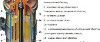
From the secondary winding of the ignition coil, a high voltage is supplied to the central electrode of the distributor, which is transmitted using a slider to the side electrodes of the distributor. The speed of rotation of the slider is equal to the speed of rotation of the camshaft and relates to crankshaft revolutions in a ratio of 1:2. The side electrodes of the distributor cover are connected to the spark plugs via high-voltage wires. The main disadvantage of this system is the difficulty in ensuring timely supply of voltage to the spark plugs at different engine speeds and operating modes. This problem was partially solved by the use of a centrifugal and vacuum ignition timing regulator, and subsequently by the use of electronic units, but did not completely solve the problem. In addition, the system has many connections and wearing contacts, which significantly reduces reliability.
Typical ignition system
Ignition system components
On the technical side, the ignition system is part of the engine electrical equipment complex.
Structurally, it consists of the following elements:
- Battery or other power source. It supplies a low voltage of 12 volts to the network.
- Switch. When you turn the key, the switch closes and low voltage flows into the energy storage device.
- Energy storage. There are two types: inductive (a transformer-type ignition coil that converts low voltage into high voltage up to 30 thousand volts) and capacitive (capacitor).
- Energy storage and distribution control unit. Depending on the type of ignition system, this may be a chopper, a transistor switch, or an ECU (electronic control unit).
- Distributor. This unit can be mechanical or electronic. It supplies certain candles with energy at a given point in time.
- High voltage circuit wires. They supply high voltage to the electrodes of the spark plugs.
- Spark plug.
The operation of the ignition system is based on the following principle: when low-voltage voltage is supplied to the network, energy is accumulated and converted, which is then distributed among the spark plugs, on the electrodes of which a spark is formed, provoking the ignition of the air-fuel mixture.
What kind of malfunctions are there?
Before solving a problem, you need to find out what caused it. Therefore, here is a list of the main malfunctions of a standard ignition coil:
- Coil overheating . This problem has only two sides: the transformer begins to overheat when driving at 50-60 kilometers per hour, or it always heats up, even when the engine is turned off. In the first case, there is a short circuit inside the transformer, and the second situation is characterized by a short circuit in the wiring. At the same time, the ignition coil has nothing to do with it. In the first case, you need to urgently replace it, and in the second, find problems related to the wiring.
- No spark . This is the most common situation that, perhaps, any owner of a Soviet “Nine” or “Lada” has encountered. In general, the situation is as follows - the engine simply refuses to start. As a rule, the easiest way to detect the problem is to remove the main cable from the distributor and keep it at a distance of 5 millimeters from the cylinder head cover. Have a partner crank the starter. If there is no spark, then the coil or commutator is faulty. The only way to know for sure is to install a known-good element and try to start the car. If the coil breaks, it still needs to be replaced.
- Other ignition system problems . These may be omissions or failures in the system. Drivers call this “dull” acceleration, when the car jerks and does not gain full power. Of course, problems can affect not only the transformer, since high-voltage cables are responsible for transmitting electrical energy. Faulty spark plugs also cause the engine to run unstably. Therefore, before drawing any conclusions, use the diagnostic methods described above.
If the coil is working properly, then the problem should be looked for in a completely different place. That's all. As you can see, the signs of a faulty step-up transformer are not so vague. We wish you good luck on the roads!
Features of the contact system
Historically, the contact system was one of the first and today it can only be found on older car models. In such designs, the formation of high voltage occurs in a transformer coil, and its distribution to the spark plugs is carried out mechanically - by closing and opening the circuit contacts with a breaker-distributor.
Contact ignition system device
In addition to the main elements, such systems include a centrifugal ignition timing regulator, which is necessary to convert the ignition timing relative to the crankshaft speed. It consists of two weights acting on a mobile plate in contact with the cam mechanism of the breaker.
Ignition timing is a certain position of the crankshaft at which high voltage is supplied to the spark plugs. In this mode, ignition occurs until the piston reaches top dead center, which ensures the most efficient combustion of the air-fuel mixture.
Also in the contact circuits, a vacuum ignition timing regulator is used, which changes the timing angle according to the operating mode (load) of the engine. It is connected to the cavity located behind the throttle valve, and when you press the gas pedal, it changes the advance angle depending on the magnitude of the vacuum.
When the contacts are closed, a low voltage is applied to the primary winding of the coil, where energy is accumulated and at the moment the contact opens, a high voltage is formed on the secondary winding. The energy then goes to the ignition distributor and then to the corresponding spark plug.
If the load on the power unit increases, the rotation speed of the chopper-distributor shaft increases, and the weights of the centrifugal regulator diverge, changing the position of the plate. This promotes earlier opening of contacts, which increases the advance angle. When the load on the engine decreases, the reverse process occurs. What are the differences between a contact-transistor ignition system? The next generation of the ignition system was a contact-transistor one, which involves installing a transistor switch coil in the primary circuit. It allows you to reduce the current in the low voltage winding, which increases the service life of the contacts.
Repair of breaker-distributor - breakdowns and how to fix them
If the car does not start or stalls, the first thing you need to pay attention to is whether fuel is entering the carburetor. If the fuel is in order, then they look at sparking. When current flows up to the breaker, but there is none further, it means that the cause is a faulty breaker. The main malfunctions of the ignition distributor-interruptor can be: burnt contacts, a broken distributor cap, a faulty slider, a jammed bearing of the ignition timing regulator, a failed Hall sensor.
After identifying a malfunction, it is necessary to repair the breaker-distributor (take it to a repair shop or do it yourself). The ignition distributor in all cars is located in an accessible place - in the upper part of the engine, since it is driven by the camshaft. To find out the cause of the problem, you must first remove the breaker cover; it is held on by two latches or two screws.
After removing the cover, you need to carefully inspect it. It may be broken (a thin dark strip), this can only be eliminated by replacing the cover. The central contact (charcoal) in the lid may fall out or the spring that presses it to the slider may burst. This problem can be easily corrected by replacing the coal. If everything is fine with the cover, you need to check the slider, and when dark streaks or a melted fuse are visible on it, then you need to replace the slider.
The classic ignition system (IS) of gasoline internal combustion engines (ICE) contains the following elements:
- Accumulator battery;
- ignition switch with key;
- ignition coil;
- breaker (included in the low-voltage circuit);
- high-voltage pulse distributor;
- cylinder spark plugs;
- high-voltage wires and lugs.
This scheme is typical for a contact ignition system. A switch has also been added to the contactless system, and on some modifications additional resistance (variator) is provided.
Contact-transistor ignition system
The next generation of the ignition system was a contact-transistor one, which involved installing a transistor switch coil in the primary circuit. It allows you to reduce the current in the low voltage winding, which increases the service life of the contacts.
ignition distribution systems appeared , that is, not moving. This became possible thanks to the switching of high-voltage coils by electronic units. This system completely adjusts the moment of spark formation depending on the speed and load on the engine. There are several schemes for implementing static distribution. In the first option, there are two cylinders with ignition timing shifted by 360 degrees. the crankshaft simultaneously receives high voltage from the ignition coil. In this case, sparking occurs simultaneously in two cylinders. Since the spark plugs are connected in series to the secondary winding of the ignition coil, the spark discharge on the spark plugs will be the same discharge in the series-connected spark gaps, and will flow in the same direction. Consequently, if on one spark plug of a pair the spark discharge arc is directed from the central electrode to the side electrode, then on the other spark plug, on the contrary, from the side to the central one. At the same time, the spark energy will be different. This is due to the environment in which the spark was generated. When one spark plug is in the cylinder where the compression stroke occurs, the other is in the cylinder where the end of the exhaust stroke occurs. High pressure is applied to one of the spark plugs and it ignites the mixture; the spark on the other spark plug jumps to idle. The energy of a spark discharge that does not ignite the mixture is the same as the total loss of current in the spark gaps between the rotor and the side contacts with high-voltage ignition distribution. The picture changes to the opposite after one beat. This method uses one coil in a two-cylinder engine and two coils in a four-cylinder engine, working in pairs 1 - 4 and 2 - 3 cylinders. The coils are controlled by a two-channel switch at the command of the controller. Often the coil control key is built into the controller.
Contact-transistor ignition system
Due to the installation of a transistor, the voltage supplied to the spark plugs is 30% greater than in a classic contact system. The gap between the electrodes and, as a consequence, the length of the spark is also larger, which means that the contact area with the air-fuel mixture also increases, which contributes to its complete combustion. In a contact-transistor ignition system, the breaker acts not on the coil, but on the switch.
When you turn the key, two types of currents begin to pass through the transistor:
- management;
- main current of the primary winding.
When the contacts open, the control circuit current disappears and the transistor turns off, preventing primary current from flowing. At this moment, the magnetic field forms a high voltage on the secondary winding. To speed up the turn-off of the transistor, a pulse transformer can be installed in a contact ignition system of this type.
Issues regarding the operation of the ignition distributor rotor
For reliable operation of the rotor, it is necessary to keep it clean and monitor the condition of the contacts. When carbon deposits or oxide form on them, the contacts are cleaned with sandpaper.
When cleaning the rotor contact with sandpaper, you must act carefully so that the gap between it and the electrodes in the distributor cap remains small
After cleaning, it is necessary to clean the slider with compressed air so that abrasive particles do not get under the distributor cap. If plaque forms without traces of charring, wipe the rotor contacts with a rag soaked in gasoline, acetone or solvent. If the rotor itself, and not just its contacts, shows signs of charring, the distributor must be urgently replaced.
Operating principle of the contactless system
An evolutionary continuation of the transistor-contact system is contactless ignition. In such designs, a special pulse sensor is installed instead of a breaker. This makes it possible to increase the service life of the ignition system due to the absence of malfunctions associated with the breaker contacts.
The sensor generates low voltage electrical pulses. It comes in three types:
- Hall Sensor . The design of such a sensor includes a permanent magnet and a semiconductor wafer equipped with a microcircuit.
- Inductive . The principle of its operation is based on changing the induction value of the sensing element depending on the size of the gap between the sensor and a moving plate rotor acting on the magnetic field.
- Optical . It consists of an LED, a phototransistor and a matching chip. When light from the diode hits the phototransistor, the sensor supplies ground (minus power) to the switch. Blocking the flow of light provokes the disappearance of the current in the coil and contributes to the further formation of a spark.
Structurally, the pulse sensor is integrated into the distributor and is regulated by the engine crankshaft rotation mode. Interruption of the current in the primary winding of the ignition coil of the contactless system is also carried out by a transistor switch, but responding to sensor signals. When the crankshaft rotates, the sensor sends voltage pulses to the switch. The latter, accordingly, generates current pulses in the low voltage winding of the coil. When no current flows, a high voltage appears on the secondary winding, which is transmitted to the distributor and then through high-voltage wires to the desired spark plug. Changing the advance angle in a contactless ignition system is also performed by centrifugal and vacuum regulators.
The operating principle of a breaker-distributor in a nutshell
The operating principle of the breaker-distributor is not complicated. The contacts open, and a magnetic field appears in the primary ignition winding, which is necessary for the formation of a high-voltage current. It returns from the coil to the distributor cap, which has a contact that touches the slider. It distributes the current across the contacts of the cover and further along the wires to. The breaker may become unusable due to “old age”, due to moisture getting inside or subsequent mechanical damage.
Over time, all parts and mechanisms in a car wear out, and the design in question also suffers from this. For example, the most common wear in the housing bushing will already lead to unstable operation of the machine, since the breaker shaft will dangle. When washing your car or when you get into a large puddle, moisture can get on the breaker, and if it is not protected, it will stop working. In the case of mechanical damage, everything is simple: someone dropped something, accidentally hit something and damaged the mechanism.
Electronic and microprocessor systems
The most modern system is considered to be electronic. It has no mechanical contacts, and therefore can also be called contactless. Electronic ignition is part of the engine management system.
In this system there is practically no voltage loss, as in the previous ones, and the operation of each spark plug does not depend on the work of other spark plugs, as in the first and second variants of static ignition. In addition, in this case, the ignition timing is precisely adjusted directly in each cylinder, which allows complete combustion of fuel, thereby reducing the emission of harmful substances into the atmosphere.
Electronic ignition system
There are two types of electronic contactless ignition systems:
- With distributor . In such a circuit, a mechanical ignition distributor is used, which supplies high voltage to a given spark plug.
- Direct ignition . With this scheme, high voltage is supplied to the spark plug electrodes directly from the coil.
In addition to the basic elements, the electronic ignition system includes:
- Input sensors . They record data about the current operating mode of the motor and supply it in the form of electronic signals to the control unit.
- Electronic control unit . It processes the signals and transmits the appropriate commands to the igniter.
- Actuator , or igniter. In fact, it is a transistor board that, in open mode, provides voltage supply to the primary winding, and in closed mode, cuts off and generates high voltage on the secondary winding of the coil.
Such systems can be equipped with one common (in designs with a distributor), individual (when energy is supplied directly to the spark plug) or dual ignition coils.
A type of electronic system is a microprocessor. It uses a whole complex of sensors, the signals of which are processed by the ECU. It calculates the optimal operating mode of the system at a given point in time. The advantages of this design are reduced fuel consumption and improved dynamic characteristics of the vehicle.
Types of distributors
In the contact SZ, on the drive shaft there are cams for opening the contacts. Accordingly, there are also contacts themselves, which are fixed in close proximity to the cam shaft. The number of cams on the shaft corresponds to the number of cylinders in the engine. To prevent the contacts from burning, the distributor has a capacitor.
The contactless distributor, instead of a mechanical contact opening device, is equipped with a Hall sensor, it performs the interruption function. Interrupt control is achieved using an electronic switch. Switches can be of two types - with additional resistance (variator) and without it. The switches have different electrical circuits, so they are not interchangeable with each other. That is, if a variator is provided in the ignition circuit, then the switch must be installed of the proper type. CVT-free switches are more modern and have better technical characteristics. An engine with this type of control is more economical and responsive, has more power and better dynamics.
Alexandra Podolskaya
The purpose of the distributor in the VAZ 2106 car is to regulate the timely supply of spark to the spark plugs. Those who are at least a little familiar with the structure of the engine know that the power stroke in the cylinders occurs alternately. Each engine has its own operating order. For example, in a VAZ 2106, the cylinders operate in this order 1-3-2-4. At the moment of the working stroke, when the piston is in the upper position, the distributor should give a spark. Otherwise, without it, there would be no uninterrupted operation of the entire mechanism.
