Basic malfunctions of the generator and relay regulator, how to eliminate them
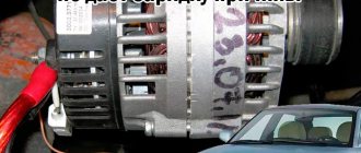
A generator in a car is an electrical unit that generates electricity to power consumers in the car and charge the battery.
Most modern cars are equipped with three-phase alternating current generators with electromagnetic excitation. To obtain direct current, generators are equipped with diode rectifiers.
What are the advantages of alternators?
The advantage of alternating current generators over direct current generators is that they have the property of self-limiting maximum current. Thus, there is no need to install a current limiter in the generator circuit; only a limiter, or rather a voltage regulator, is sufficient.
If there were no voltage regulator, then with an increase in the engine crankshaft speed, and accordingly with an increase in the number of revolutions of the generator rotor, the voltage produced by the generator would sharply increase, which could damage the electrical consumers in the car.
In addition, such generators are simpler in design, cheaper, have smaller dimensions and weight than DC generators.
What malfunctions can occur in the generator?
The most typical malfunctions of a car generator include: break or short circuit of the turns of the stator winding, or field winding (it is located on the rotor), contamination or burning of slip rings, malfunctions of the brush unit, that is, wear of the brushes or their freezing, failure of the rectifier unit, wear rotor shaft bearings, broken wires of output terminals.
How are such malfunctions resolved?
Short circuits of winding turns or their breakage are eliminated either by soldering or by rewinding the windings in a special workshop. It is difficult to carry out such repairs independently and without special equipment. Sometimes it makes sense not to repair the generator, but to buy a new one, since repairs associated with rewinding the windings are quite expensive.
If the wires are broken, for example, from the output terminals, then they can be soldered.
Contaminated slip rings are washed with gasoline and then dried in air. If the rings are oxidized or burnt, they can be cleaned with fine-grained sandpaper, blown with compressed air, and then washed with gasoline. In some cases, the rings are processed on a lathe.
Worn brushes (usually if their height is less than 8-10 mm) are replaced with new ones. Old but unworn brushes are wiped free of dirt with a clean rag and washed in gasoline. Brush holders are also cleaned in the same way. In some cases, the entire brush assembly has to be replaced.
A faulty rectifier unit, as a rule, is not repaired, but simply replaced with a new one.
Faulty or worn rotor shaft bearings are replaced with new ones. To eliminate other, more complex faults, the generator is sent for repair to a specialized workshop.
Video: how to find the cause of a breakdown of a VAZ classic generator with a remote voltage regulator.
What malfunctions can occur in the voltage regulator?
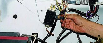
Sometimes the cause of generator malfunctions is a malfunction in the relay regulator. This is usually due to burnout of transistors, resistors, or failure of other parts. Often relay regulators are not repaired, but simply replaced with new ones, but it happens that after simple repairs they can be restored.
Of course, such repairs should be carried out by a person who understands electrical engineering.
What to do if the voltage regulator fails on the road?
By the way, if the relay regulator fails on the road, then you can continue driving, but you need to periodically, after every hour of travel, disconnect the connector from the regulator and connect the “+” and “Ш” terminals on the regulator with a suitable wire.
It is necessary to maintain such a driving mode that the charging current does not exceed 20-25A, and at the same time turn on the maximum number of electricity consumers. After half an hour of travel, the wire from the terminals should be disconnected so as not to overcharge the battery.
Tips for motorists
The VAZ-2110 turn indicators include six lamps located on the right and left sides of the car, two light signaling lamps on the instrument panel, a turn signal breaker relay and a fuse located in the mounting block, and controls all this under the steering switch.
The hazard warning lights work together with the direction indicators , and all wiring goes through the plug block of the hazard warning light button. Therefore, malfunctions that occur on this button also lead to failures in the direction indicators.
The most common malfunction of turn signals on a VAZ 2110 is the burnout of one of the lamps, which should have worked after it was turned on. A warning lamp will notify you of this. Its blinking frequency will increase exactly twice, which will be clearly visible to the driver who glances at the instrument panel. When replacing a burnt-out lamp, pay attention to its power; you need to replace it with exactly the same one, otherwise the light alarm will not work normally.
If the turn signals do not turn on on either the right or left side of the car. Then you will have to open the mounting block and check fuse F16. If this fuse is intact, pay attention to the relay breaker K3, it may have failed. You can check it as follows. You need to open the relay cover and, with the ignition on, bridge two contacts located perpendicular to each other using a piece of wire. If the turn signal lamps start to light without blinking, then this relay will have to be replaced, as it is faulty. But if the lamps do not light, then you will need to check the wires and plug blocks for lack of contact.
The culprit for the turn signals not turning on may also be under the steering switch . It can also be checked quite easily. To do this, you will need to remove the cover from the steering column and disconnect the plug block from the steering switch. Then, you should short-circuit the two terminals to which the wires fit, blue (or blue-black) and blue-red. If the turn signal works, you will have to replace it with a steering switch; if it doesn’t work, then the hazard is most likely the hazard warning button or there is no contact somewhere in the wiring.
There may also be purely mechanical faults with switch under the steering wheel . However, it will not automatically return to the off position when the turn is completed. The driver will have to remember to turn it off himself, and when he gets tired of doing this, he will have to replace the steering switch.
More complex malfunctions may also occur in the operation of direction indicators , which the driver is unlikely to be able to find. In this case, there is only one way out: contact qualified specialists, automotive electricians.
Turning lights are an integral element of optics in any modern car. Their purpose is to warn other road users that the driver is planning to make a maneuver. For what reasons do turn signals and emergency lights not work, how to check the functionality of optical elements and how to repair them. We will talk about this below.
Basic generator malfunctions
The most common faults
car generator include:
- break or short circuit of the stator winding turns;
- break or short circuit of the field winding turns (it is located on the rotor);
- contamination or burning of contact rings;
- malfunction of the brush assembly (the most common malfunction);
- brush wear or freezing;
- failure of the rectifier unit;
- wear of the rotor shaft bearings;
- broken wires at the output terminals.
Removing relay type 494.3747 or 642.3747
1. Under the instrument panel on the driver’s side, disconnect the connecting block from the turn signal relay
2. Using a 10mm wrench, unscrew the nut and remove the relay.
Diagram for checking the presence of voltage in the relay block
Relay test circuit
Electronic breakers type 494.3747 and 642.3747 do not require maintenance during operation.
These breakers cannot be repaired; if they fail, they must be replaced.
Relay test
Install the new relay in reverse order.
Testing and Troubleshooting Methods
Short circuit of winding turns or their breakage
eliminated either by soldering or rewinding the windings in a special workshop. It is difficult to carry out such repairs independently and without special equipment. Sometimes it makes sense not to repair the generator, but to buy a new one, since repairs associated with rewinding the windings are quite expensive.
If the wires are broken, for example, from the output terminals, then they can be soldered.
Dirty slip rings
washed with gasoline and then dried in air. If the rings are oxidized or burnt, they can be cleaned with fine-grained sandpaper, blown with compressed air, and then washed with gasoline. In some cases, the rings are processed on a lathe.
Worn brushes
(usually if their height is less than 8-10 mm), replace them with new ones. Old but unworn brushes are wiped free of dirt with a clean rag and washed in gasoline. Brush holders are also cleaned in the same way. In some cases, the entire brush assembly has to be replaced.
Faulty rectifier unit
, as a rule, they are not repaired, but simply replaced with a new one.
Faulty or worn rotor shaft bearings
replaced with new ones. To eliminate other, more complex faults, the generator is sent for repair to a specialized workshop.
Voltage regulator relay malfunctions
Sometimes the cause of generator malfunctions is a malfunction in the relay regulator. This is usually due to burnout of transistors, resistors, or failure of other parts. Often relay regulators are not repaired, but simply replaced with new ones, but it happens that after simple repairs they can be restored.
Of course, such repairs should be carried out by a person who understands electrical engineering.
What to do if the relay regulator breaks down on the road
If the relay regulator breaks down on the road, then you can continue driving, but you need to periodically, after every hour of travel, disconnect the connector from the regulator and connect the “+” and “W” terminals on the regulator itself with a suitable wire.
It is necessary to maintain such a driving mode that the charging current does not exceed 20-25A, and at the same time turn on the maximum number of electricity consumers. After half an hour of travel, the wire from the terminals should be disconnected so as not to overcharge the battery.
Malfunctions of the relay regulator
A typical malfunction of the relay regulator is untimely switching on and off of the voltage regulator, current limiter and reverse current relay as a result of changes in the tension force of the armature spring, the gap between the armature and the core, or due to oxidation and welding of the relay contacts. The adjustment state of the relay regulator has a significant impact on the service life of the battery. A systematic increase in the regulated voltage by 10% against the optimal one reduces the service life of the battery by 20 thousand km of vehicle mileage (If the rules of operation and maintenance of batteries are followed, their service life before major repairs can range from 80 to 120 thousand km of vehicle mileage).
Signs indicating that the regulated voltage is too high are:
- boiling and splashing of electrolyte through the ventilation holes in the battery cover
- charging current exceeding 5 A, not decreasing during 4-6 hours of continuous driving
- frequent burnout of light bulbs in lighting fixtures
The relay-regulator can be checked and adjusted on stands in the removed state, as well as directly on the car using portable devices NIIAT E-5 and NIIAT LE-1 or separate measuring instruments (voltmeter with a scale of up to 30 V, ammeter with a scale of 30 - 0 - 30 A, tachometer at 10,000 rpm and rheostat at 25 A, 15 ohm).
Checking the voltage regulator consists of determining the value of the regulated voltage, which must correspond to the technical specifications for this type of relay-regulator and the conditions of its testing (the number of revolutions of the generator armature, the magnitude of the load current, the time of year, etc.).
Rice. Checking the voltage regulator with the LE-1 device
When checking the voltage regulator on a car using the LE-1 device, the battery wire is disconnected from terminal “B” of the relay regulator and instead, terminals II and V of the device are connected to measure the current and voltage of the generator. Terminal M is connected to the ground of the vehicle, and Terminal P is connected to the output of the breaker to activate the electric tachometer.
After starting the engine, use the tachometer to set the crankshaft speed according to the characteristics of the generator (1500 - 2000 rpm) or the corresponding generator armature speed (3000 rpm). Turn the nut R on to turn on the rheostat and check the voltage value regulated by the regulator. The voltmeter readings must correspond to the required value of the regulated voltage. For example, for the central climatic region, the regulated voltage when the battery is installed externally throughout the year should be 14.2 V, and when installed under the hood - 13.7 V.
The voltage regulator is adjusted only if the value of the regulated voltage differs from that required by specifications by ± 0.5 V.
The adjustment accuracy of the voltage regulator allows deviations of no more than ± 0.2 V.
Checking the reverse current relay consists of determining the voltage value at which the relay contacts close (in this case, the current from the generator is supplied to charge the battery and to power the switched-on consumers), and the value of the reverse current at the moment they open (in this case, the battery supplies electrical energy all enabled consumers).
When checking with a voltammeter LE-1 the amount of reverse current opening the relay contacts, connect the battery wire disconnected from terminal B of the relay-regulator to terminal 1 of the device, and terminal II of the device to terminal B of the relay-regulator. Then turn on the load rheostat with nut 9 and start the engine, increasing the number of crankshaft revolutions until the reverse current relay turns on.
Rice. Checking the reverse current value using the LE-1 device
The ammeter at this moment will show the amount of charging current. Next, the engine speed is gradually reduced, observing the ammeter readings for a decrease in the charging current of the battery. By reducing the speed of the engine crankshaft or the generator armature shaft, respectively. reduce the charging current of the battery. When the ammeter needle reaches zero, the ground polarity switch is switched to reverse polarity. At the moment the reverse current relay contacts open, the ammeter needle will deviate from the zero position and show the maximum discharge current or the value of the reverse current of the relay contacts opening, which should be within 0.5-0.6 s. After this, the arrow will return to zero. If the reverse current does not correspond to the permissible value, the gap between the relay contacts is adjusted.
When checking the turn-on voltage of the reverse current relay using a voltamperl gauge LE-1, connect the wire according to the diagram shown in the figure.
Rice. Checking the turn-on voltage of the reverse current relay using the LE-1 device
Turn on the rheostat 10 and set the load from 5 to 10 A. Then start the engine and gradually increase its speed, observing the readings of voltmeter 7. The voltage initially gradually increases, but at the moment the reverse current relay contacts close, the voltmeter needle sharply deviates to the left. The maximum voltage before the voltmeter needle deflects must correspond to the standard value (depending on the time of year and location of the battery installation).
Checking the current limiter consists of determining the maximum value of the load current indicated by the ammeter according to the given current limiter adjustment.
When checking the current limiter, the connection diagram of the devices remains the same as when checking the voltage regulator (see Fig. 68). Having started the engine, set the engine crankshaft speed to 1500 - 2500 rpm, which corresponds to 3000 - 3500 rpm of the generator armature.
At a steady speed, the generator load is gradually increased using a rheostat and the ammeter readings are observed. As the load increases, there comes a time when, despite the decrease in the resistance of the rheostat, the ammeter needle stops. This is the maximum current value (17-21 a) and will correspond to the required value. If the maximum current deviates by more than ± 1 A, the limiter is adjusted.
Before adjustment, an external inspection of the relay-regulator is carried out, cleaned of dirt, damage to the insulation is eliminated, fastenings are checked, traces of burnt contacts are eliminated and they are cleaned with glass sandpaper (100 grit). Before starting the adjustment, check and set the required gap between the armature and the core. The gap between the armature and the core of the voltage regulator and current limiter with closed contacts should be 1.4-1.5 mm. This gap is adjusted by moving the rack stop while the fastening screws are loosened.
For a reverse current relay, the gap between the armature and the core washer should be 1.4-1.5 mm with open contacts with a gap between them of at least 0.25 mm. The gaps between the armature and the core are adjusted by bending the armature travel limiter, and between the contacts by bending the fixed contact post.
The voltage maintained by the regulator and the current regulated by the limiter are adjusted by changing the tension of the armature spring by bending the shank of the spring holder. The spring tension of the reverse current relay is adjusted by bending the spring post. The relay-regulator is checked and adjusted after 5.5 - 8.5 thousand kilometers, as well as when the operating season changes.
Checking the solenoid relay
When the battery is charged, but the engine does not start, you need to check the starter.
If the generator spins but the engine does not, then in such cases it is necessary to check the solenoid relay of the electric motor and the bendix. To do this, you need to remove the starter. After this, all contacts are cleaned, and the resistance of the relay winding is measured with a multimeter. If the value is infinity, then the winding has burned out. In this case, it is necessary to rewind the coil or replace it. The device shows several tens of ohms, which means the winding is intact.
Then its performance is checked. The positive terminal of the battery is connected to the corresponding relay terminal using the cigarette lighter. And the minus is connected to the starter housing. A click should be heard, then the device is working properly, otherwise it needs to be disassembled and the mechanical part checked.
This article was produced by our experienced team of editors and researchers, who reviewed it for accuracy and comprehensiveness.
wikiHow's content management team carefully monitors the work of its editors to ensure that every article meets our high quality standards.
Read also: Wrought iron floor hangers for clothes
A relay is a separate device (as opposed to integrated circuits) used to control high power signals with low power signals. The relay separates and protects the low voltage circuit from the high voltage circuit by means of an electromagnetic coil. This article will tell you how to test both the relay (solid state) and the coil.
When any electrical equipment in a car stops working, the first thing to check is the fuse responsible for the problematic element. If the fuse is intact, then the problem may lie in the relay.
Relays are found in many electrical circuits of a car: fuel pump, power windows, heated windows, heated seats and many others. That is why it is important to be able to independently test the relay for functionality using a conventional multimeter.
How to check the generator voltage regulator relay
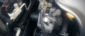
The electrical network of any car is powered by a generator, which is driven by the engine using a belt drive. Its revolutions are constantly changing, ranging from 900 to several thousand, causing the rotor to rotate accordingly. For the normal operation of all electrical appliances and charging the battery, the voltage in the on-board network must be stable, which is ensured by the relay regulator. Being the weakest link in the power supply system, the device first of all needs to be checked when problems with battery charging and other breakdowns in the vehicle's electrical network are detected.
Principle of operation
The autogenerator voltage regulator is designed to maintain the voltage of the on-board network within the required limits under any operating mode and at different generator speeds, load changes and changes in external temperature. It is also capable of performing additional functions - protecting the generator from overloads and emergency operation, automatically connecting the excitation windings or the generator failure alarm system to the on-board circuit.
The operation of any voltage regulator is based on the same principle and is determined by the following factors:
- Rotor speed.
- The current strength that the generator delivers to the load.
- An indicator of the magnetic flux created by the field winding current.
Higher rotor speeds determine an increase in generator voltage. An increase in current strength on the excitation winding makes the magnetic flux stronger, and at the same time the voltage. Any voltage regulator stabilizes it by changing the excitation current. When the voltage increases or decreases, the regulator decreases or increases the excitation current, regulating the voltage within the required limits.
The relay regulator itself is an electronic circuit with outputs to graphite brushes. It is installed both in the generator body itself next to the brushes, and outside it, and then the brushes are attached to the brush holder.
Malfunctions
Most often, the relay regulator fails for the following reasons:
- When the battery is working properly, there is no charging current, which is why it does not charge. This happens when the wires are poorly connected to the relay terminals or when the circuit from the generator to the battery is broken. Eliminated by fixing the wire in the circuit, checking and adjusting the voltage regulator and relay regulator.
- Insufficient charging current with a discharged battery or high current with a fully charged battery is caused by a malfunction of the voltage regulator. It can be eliminated by adjusting the device or replacing it.
- Burning and burnout of lamps with excessive heat occurs when the adjustment of the relay regulator is violated or the contacts are closed. Eliminated by disconnecting and cleaning the closed contacts, adjusting or replacing the voltage regulator.
- High discharge current after stopping the motor. Occurs when the relay-regulator contacts close (contacts sintering, armature spring breaks) or the electrical wire short circuits. It is repaired by finding and eliminating a short circuit with the battery disconnected, checking and adjusting the current limiter, opening and cleaning the contacts, replacing the spring and adjusting its clearance and tension.
How to check the relay regulator
Failure of the relay regulator manifests itself in systematic undercharging or overcharging of the battery. The simplest test of the device is carried out with a tester in voltmeter mode at direct current ranging from 0 to 20V. When the engine is not running, the probes of the device are connected to the battery terminals and record the voltmeter readings, which vary within 12-12.8 V depending on the battery condition.
Afterwards, start the engine and look at the instrument readings: the voltage should increase to 13-13.8 V, depending on the crankshaft speed. A further increase in speed should correspondingly increase the voltage. So, at an average rotation speed it is 13.5-14 V, and at maximum it reaches 14-14.5 V. The absence of an increase in voltage after starting the engine indicates a malfunction of the relay regulator.
There is a possibility that the battery is not charging for another reason, for example, due to a malfunction in the generator itself. In order to establish a diagnosis, the relay-regulator is removed for a more accurate check using a tester and a 12-volt lamp. Additionally, you will need wires with terminals, a power supply or a charger in which the current can be adjusted.
After connecting the relay to the circuit and turning on the power supply, the lamp will light up. Use the voltage regulator to gradually increase the current and monitor the readings of the voltmeter or the scale of the connected tester. When readings are up to 14.5 V, the lamp should be on, and after exceeding it should go out. If, after decreasing below 14.5, it lights up again, then the relay-regulator is working. If the operation deviates in one direction or another, the relay will overcharge or not provide the necessary current for charging, which is a reason for replacing it.
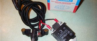
Integrated relays, popularly called “chocolate bars,” used on older models of domestic cars are tested in a similar way. The circuit is also connected to the power supply or charger via a light bulb, which should go out when the required voltage limit is reached. In this case, you need to pay attention to the condition of the terminals, which, if dirty or oxidized, can create additional resistance and, if the relay is working, cause a loss of voltage.
Relay diagnostics
- Remove the relay from the holder.
- Turn on the ignition and the corresponding switch.
- Using a voltage tester, check if there is voltage at terminal 30(+) of the relay holder. To do this, connect the device to ground (-), and carefully insert the other tip of the device into terminal 30. If the device’s LED lights up, there is voltage. If the device shows no voltage, check the diagram to see if there is an open in the path from the positive pole (+) of the battery to terminal 30.
- Prepare a jumper from insulated wire with stripped ends.
- Connect a jumper between terminal 30 in the relay holder (+ battery, always supplies voltage) with the output of the relay NO contact (terminal 37). This simulates the operation of a working relay. Where the terminals are located in the relay holder is indicated on the relay.
- If the consumer operates when the jumper is on, we can conclude that the relay is faulty.
- If the consumer does not work, find out whether the ground connection to the consumer is OK. Then check the connection from terminal 87 to the consumer. If there is a break, fix the problem.
- If necessary, insert a new relay.
If the malfunction appears intermittently, the cause is usually the relay.
In this case, sticking of contacts may occur. In this case, lightly tap the relay body with your finger. If the relay operates, replace it. How to quickly check the functionality of a relay
Replacing the generator regulator relay
Relay replacement is necessary in the following cases:
- Wear of the brushes, in which contact with the relay-regulator disappears and the generator does not work.
- A breakdown in the device circuit, which causes an increase in voltage in the system.
- Damage to the fasteners or housing, which can lead to a short circuit.
The process of replacing a device is considered using the Lada-Kalina generator as an example. Replacing the relay regulator is associated with dismantling the generator, and is carried out in the following order:
- Removing the minus terminal from the generator.
- Dismantling the generator.
3. Unsnap the plastic clips on the generator cover and remove it.
4. Disconnect the diode bridge connector.
5. Unscrewing the nut and dismantling the contact group bushing.
6. Unscrewing a pair of screws holding the relay regulator.
Checking the voltage relay
Checking the generator voltage regulator may be necessary when problems with the battery begin to occur. In particular, it began to undercharge or overcharge. When such a malfunction occurs, it’s time to check the generator voltage regulator relay.
The relay should turn off at 14.2-14.5V
The task of this simple device is to regulate the voltage of the electric current that is supplied from the generator to the battery. When it fails, the battery is either not charged enough or, on the contrary, overcharged, which is also dangerous, since this significantly reduces the battery life.
Agree that such a prospect is not very good because of one small detail. This is why it is so important to monitor the operating condition of the voltage regulator (it can also be called a pill or a chocolate bar). But in order to properly check the voltage regulator, you need to know its type and several important features.
Checking the starter regulator
To check the starter regulator relay without removing it from the car, you can use a multimeter and test all the wires that go to it. To do this, they are first disconnected from the regulator. The multimeter is switched to resistance measurement mode, the disconnected wires are checked.
If everything is normal, then the conductors are returned to their place. The voltage at the battery terminals is measured with the engine off. The multimeter is switched to DC voltage measurement mode in the range from 0 to 20 Volts. The probes attach to the battery terminals. The device should show 12.2-12.7 V.
If 12 volts or lower, then it needs to be recharged.
Then the engine must be started and checked again with the same measurements. If the voltage is in the range of 13.2-14 V, then this is normal. We add engine speed to 2000 per minute and measure again. Normally, the multimeter should show between 13.6-14.2 V. We also add revolutions to 3500 per minute.
Types of Voltage Regulators
Having understood what types of these devices there are, what their features and properties are, a complete understanding of the procedures carried out during testing will come. This will also give the answer to what scheme, in what way and how to check the generator voltage regulator. There are two types of regulators:
In the first case, it is meant that the regulator housing is combined with the brush assembly directly in the generator housing. In the second case, the regulator is a separate unit, which is located on the car body, in the engine compartment, and wires from the generator go to it, and wires from it go to the battery.
A special feature of the regulators is that their housings are non-separable. They are usually filled with sealant or special resin. And there is no particular point in repairing them, since the device is inexpensive. Therefore, the main problem in this regard is to check the generator voltage regulator relay. Regardless of the type of regulator, the voltage symptoms will be the same.
Operating principle of the generator voltage regulator
p, blockquote 5,0,0,0,0 –>
The generator is one of the most conservative components of cars. Developed in the mid-60s, the circuit has remained virtually unchanged to this day, with the exception of the element base.
p, blockquote 6,0,0,0,0 –>
Scheme
In general, the circuit of a car generator can be depicted as follows:
p, blockquote 7,0,0,0,0 –>
p, blockquote 8,0,0,0,0 –>
It contains the following main components:
p, blockquote 9,0,0,0,0 –>
- rectifier bridge 5 and 6;
- rectifier bridge for power supply of relay-regulator 7;
- relay-regulator 11;
- excitation winding brushes 10;
- field winding (armature) 9;
- stator winding 8;
- indicator lamp 4;
- battery 3;
- ignition switch contact group 1;
- capacitor 2 (may be missing).
The general principle of operation of alternating current generators was invented by the brilliant Tesla. A direct current through the field winding induces a magnetic field. During the rotation of the field coil (armature) inside the stator winding, an alternating voltage is generated in the latter.
p, blockquote 10,0,0,0,0 –> adsp-pro-1 –>
This voltage is converted to constant voltage by a rectifier made on a diode bridge 5 and 6. The rectified voltage charges the battery.
p, blockquote 11,0,0,0,0 –>
The higher the current in the field winding, the higher the generator voltage will be.
p, blockquote 12,0,1,0,0 –>
What function does the relay regulator perform? Essentially it is a feedback amplifier. That is, as soon as the voltage increases, its circuit reduces the current through the field winding.
p, blockquote 13,0,0,0,0 –>
Accordingly, the generator voltage decreases. Then it increases the winding current, the generator voltage increases. And so on ad infinitum. Ultimately, the generator voltage stabilizes at a certain level. This entire stabilization process lasts a fraction of a second.
p, blockquote 14,0,0,0,0 –>
Relay regulators are classified according to the element base of their design
:
p, blockquote 15,0,0,0,0 –>
- relay;
- transistor-relay;
- transistor (in cars before the 90s);
- integral (in modern cars);
- microprocessor-based with program control (Audi, BMW).
p, blockquote 16,0,0,0,0 –>
By design
:
p, blockquote 17,0,0,0,0 –>
- external, fixed to body elements;
- built-in;
- built-in, combined with brushes.
p, blockquote 18,0,0,0,0 –>
In modern cars, devices combined with brushes are most often used. This has its drawback: when the brushes wear out, the relay regulator also has to be changed. Conversely, failure of the relay regulator can lead to the replacement of healthy brushes.
p, blockquote 19,0,0,0,0 –>
Some specialists only change the brushes located together with the relay regulator. This is not the best option for reasons of reliability, especially since the cost of relay regulators for common cars is not so high and may even be lower than the cost of replacing brushes.
Symptoms of a problem
So, in case of low voltage, the battery simply will not charge. That is, in the morning you will not be able to start the car, the lights on the dashboard may not even light up, or troubles will arise while driving. For example, dim headlights at night, unstable operation of the electrical system (problems with electrical appliances - wipers, heaters, radio, etc.).
In case of increased voltage, there is a high probability of a decrease in the electrolyte level in the battery banks, or its boiling. A white coating may also appear on the battery case. When overcharging, the battery may behave inappropriately.
Signs, malfunctions and repair of the generator and voltage regulator
In addition, you can also identify the following signs of a faulty voltage regulator (in some cases, some of them may or may not be present, it all depends on the specific situation):
- the control light on the dashboard (although this may be a sign of other malfunctions, for example, that it has burned out, the contact has fallen out, and so on);
- after starting, the battery indicator on the dashboard does not go out, that is, there are obvious malfunctions in charging the battery;
- the brightness of the headlights becomes dependent on the engine speed (you can check this somewhere in a deserted place by placing the car against a wall and accelerating - if the glow changes, then most likely the voltage regulator is faulty);
- the car stopped starting normally the first time;
- The battery is constantly ;
- when the engine speed exceeds 2000 rpm, the indicators on the dashboard turn off ;
- the dynamic characteristics of the car decrease , this is especially noticeable at high engine speeds;
- In some cases, the battery may boil .
Main symptoms of a malfunction
p, blockquote 24,0,0,0,0 –>
The very first sign of a malfunction is the absence of a warning light (indicator) on the dashboard when the ignition is turned on.
p, blockquote 25,1,0,0,0 –>
In older cars, where the battery charging pattern is similar to that shown in the first figure, it is too early for car enthusiasts to panic. Perhaps it was just a burnt out light bulb or a broken connection, and these cases are quite common. Car owners remove the generator and take it for testing, but in vain.
p, blockquote 26,0,0,0,0 –>
The second sign is that the “battery” indicator does not go out after starting the engine. This already indicates a violation of the charging process and a possible malfunction of the generator.
p, blockquote 27,0,0,0,0 –>
Another sign of a malfunction is that the brightness of the low and high beams depends on the engine speed. By the way, it is recommended to carry out such a check regularly. To do this, you need to stop in the dark in a quiet place in front of some building and turn on the high beams in neutral. A change in brightness indicates possible problems with the charging system.
p, blockquote 28,0,0,0,0 –>
The smell of burnt windings in the cabin is also a sign of a generator malfunction, but you may not notice it.
p, blockquote 29,0,0,0,0 –>
Reasons for failure of the relay regulator
The reasons for the failure of the voltage regulator may be:
- short circuit in the circuit, including interturn short circuit of the excitation winding;
- failure of the rectifier bridge (diode breakdown);
- reverse polarity or incorrect connection to the battery terminals;
- penetration of moisture into the housing of the regulator and/or generator (for example, when washing a car or driving in heavy rain);
- mechanical damage to the unit;
- natural wear and tear of the unit, including brushes;
- poor quality of the device being directly tested.
There are a number of simple methods for checking the regulator, regardless of whether the unit is removable or not.
Troubleshooting if turns do not work, even if you do not have special knowledge.
Checking the serviceability of the turn relay.
And so let’s look at what to do if the turns of a front-wheel drive VAZ, except for the 2170 Priora, do not work. The operation and troubleshooting of which was discussed in the article “Prior Turning Relay”.
First, make sure that the measuring instruments and control lamps on the instrument panel are working. If they do not work, then check the fuse.
If the devices are working properly, turn on the hazard warning button and check that all the lamps in the direction indicators are blinking. This will allow you to divide the circuit into two parts and speed up troubleshooting.
If the alarm does not work when turned on, then it is necessary to check the serviceability of the turn and alarm relay and the presence of power at its terminal 49. The pin designation is marked on the bottom of the relay, next to the contact legs.
We remove the relay, which is marked in the form of a triangle on the top of the case, from the mounting block, and in the vacated socket, using a test paw, check for the presence of a plus on pin 49. We connect the test lamp to the ground or minus of the battery, and with the other end we touch pin 49, when If the hazard warning button is on, you do not need to turn on the ignition. Lack of power indicates a faulty fuse, alarm button or broken wires, contact tracks of the mounting block and poor contact in the connectors.
If there is a plus on the terminal, then connect terminals 49 and 49A with a copper wire. If the connecting wires and connectors are in good condition, all the direction indicator lamps should light up. This indicates that the turn signal and light signaling relay is faulty. If the lamps do not light up, but there is a plus on pin 49, then there may be a short circuit in the signal lamp circuit and the fuse has blown. A short circuit can also cause the relay to fail. In this case, check the serviceability of the fuse, and if it blows, eliminate the short circuit in the signal lamp circuit.
The simplest way to check the generator voltage regulator
The simplest method of checking the regulator is to measure the voltage at the battery terminals with a multimeter. However, it is worth immediately making a reservation that the algorithm given below does not give a 100% probability of failure of the regulator. Perhaps the generator itself has failed. But the advantage of this method is that it is simple and there is no need to dismantle the device from the car. So, the algorithm for checking the generator voltage regulator with a multimeter is as follows:
- Set the tester to DC voltage measurement mode at a limit of about 20 V (depending on the specific model, the main thing is that it displays values up to 20 V as accurately as possible).
- Start the engine.
- Measure the voltage at the battery terminals in idle mode (1000. 1500 rpm). If the regulator and generator are working properly, the value should be within 13.2. 14 V.
- Increase the speed to 2000. 2500 rpm. In the normal state of the electrical circuit, the corresponding voltage will increase to 13.6. 14.2 V.
- When the speed increases to 3500 rpm and above, the voltage should not exceed 14.5 V.
If during the test the voltage values are very different from those given, then most likely the machine’s voltage regulator is faulty. Remember that the voltage should not fall below 12V and should not rise above 14.5V.
As mentioned above, the regulator can be separate or combined with a generator. Currently, almost all foreign cars, and most modern domestic cars, have combined relays installed. This is due to the specifics of their work and space saving.
How to check the generator relay with a multimeter without removing it from the car?
Signs of regulator failure are clearly visible. Especially if the temperature outside is sub-zero. The battery will always be either undercharged or overcharged. In the first case, a weak battery charge can be easily determined by how the starter turns the engine. He will barely twist it, and to no avail. Sometimes when you turn the key, nothing happens at all, and the lights on the panel go out.
Recharging the battery is practically no different. The same thing will happen, plus the electrolyte from the battery cans will boil away. Overcharge can be determined by the decrease in electrolyte in the banks. As a result of evaporation, a white coating may also form on top of the battery. Parts of the body under the battery may also have a white coating. Usually, with such symptoms, drivers think that the battery is damaged, but in fact there is nothing wrong with it, but the problem is in the relay-regulator, and that is what you need to pay attention to first. But to do this, you must know how to test a relay with a multimeter.
This is not difficult to do. To do this, take our multimeter and set it to voltmeter mode. With its help, we can measure the voltage when the motor is turned on. Note that when the engine is turned off, the normal voltage should be in the range of 12.4-12.7 V. If, for example, the voltage is 12 V, then the battery needs to be charged and the reasons for the undercharging should be looked for.
Checking the combined relay-regulator
Checking the VAZ 2110 voltage regulator
To perform the corresponding check, it is necessary to assemble the circuit shown in the figure. To do this, use a charger or power supply with an adjustable load (it is important that it be used to regulate the voltage value in the circuit), a 12 V light bulb (for example, from a turn signal or headlight, with a power of 3.4 W), a multimeter, and the regulator itself voltage (this can be from a Bosch, Valeo or other generator). It is advisable to have the wires used for switching with “crocodiles”.
Checking the voltage regulator of the generator 37.3701: 1 - battery; 2 — ground terminal of the voltage regulator; 3 - voltage regulator; 4 – terminal “Ш” of the regulator; 5 — output “B” of the regulator; 6 — control lamp; 7 — terminal “B” of the voltage regulator.
If you assemble a circuit in which the voltage is at a standard value of 12.7 V, then the light bulb will simply glow. But if you use a voltage regulator to raise its value to 14.14.5 V, then if the relay is working, the light should go out. Otherwise the regulator is faulty. That is, when the voltage reaches 14.14.5 V (depending on the model of the machine and, accordingly, the regulator) and above, the light goes out, and when it drops to the same level, it lights up again.
Checking the VAZ 2107 voltage regulator
Checking the voltage regulator on VAZ 2108/2109 cars
Until 1996, a VAZ 2107 with a 37.3701 generator was equipped with an old-style voltage regulator (17.3702). The verification procedure is given above. After 1996, a more modern generator of the G-222 brand was used (integrated regulator RN Ya112V (V1).
As you can see, the verification algorithm for all regulators is almost the same. The only difference is the cutoff values when the relay is activated.
Video “Budget option for repairing a steering column switch”
The video below presents an inexpensive option for repairing the steering column switch in a Peugeot car (the author of the video is the EzjikOnline channel).
The cause of non-functioning electrical equipment in the car (for example, fuel pump, heated seats, heated windows, power windows, etc.) may be a faulty relay. Let's look at a simple way to test a car relay for functionality with your own hands.
Connection diagram for 4 and 5 contact relays:
To check the relay you need (all relay contacts are labeled, and the power contacts usually have a yellowish tint):
- Apply 12 V voltage (for example, from a battery) to the terminals of the relay coil winding (control contacts 85 and 86).
- Measure the resistance (multimeter in ohmmeter mode) between the power terminals (30 and 87).
If the relay is working, then when voltage is applied there will be a click and the resistance will become close to zero (infinitesimal). Otherwise, the relay is faulty and must be replaced.
Feature of checking a 5-pin relay : contacts 30 and 88 must be closed, and when voltage is applied to the control contacts (85 and 86) they must open. Otherwise the relay is faulty.
The relay testing process is also presented in the video:
Let us remind you that another cause of electrical equipment malfunction in the car may be a broken wiring or short circuit. You can also determine the cause using a multimeter.
Key words: universal article
Checking an Individual Regulator
Checking the voltage regulator of the G-222 generator: 1 - battery; 2 - voltage regulator; 3 - control lamp.
As a rule, separate voltage regulators were installed on old cars, including domestic VAZs. But some manufacturers continue to do this to this day. The verification process is similar. To do this, you need to have a power supply with a voltage regulator, a 12 V light bulb, a multimeter and a directly tested regulator.
To check, you need to assemble the circuit shown in the figure. The process itself is similar to the one above. In normal condition (at a voltage of 12 V), the light bulb lights up. When the voltage value increases to 14.5 V, it goes out, and when it decreases, it lights up again. If during the process the lamp lights up or goes out at other values, it means that the regulator has failed.
Checking relay type 591.3702-01
Relay test diagram type 591.3702-01
You can also still find a voltage regulator of type 591.3702-01, which was installed on rear-wheel drive VAZs (from VAZ 2101 to VAZ 2107), GAZ and Moskvich. The device is mounted separately and installed on the body. In general, the test is similar to that described above, but the differences are in the contacts used.
In particular, it has two main contacts - “67” and “15”. The first of them is a minus, and the second is a plus. Accordingly, to check it is necessary to assemble the circuit shown in the figure. The verification principle remains the same. In normal condition, at a voltage of 12 V, the light bulb lights up, and when the corresponding value increases to 14.5 V, it goes out. When the value returns to its original value, the light comes on again.
A classic regulator of this type is a device of the PP-380 brand, installed on VAZ 2101 and VAZ 2102 cars. We provide reference data regarding this regulator.
| Adjustable voltage at regulator and ambient temperature (50±3)° C, V: | |
| at the first stage | no more than 0.7 |
| on the second stage | 14,2 ± 0,3 |
| Resistance between plug “15” and ground, Ohm | 17,7 ± 2 |
| Resistance between plug “15” and plug “67” with open contacts, Ohm | 5,65 ± 0,3 |
| Air gap between armature and core, mm | 1,4 ± 0,07 |
| Distance between second stage contacts, mm | 0,45 ± 0,1 |
Testing a three-level relay
Regulated power supply
Some car owners install on their cars, instead of standard “chocolate bars,” three-level relays, which are technologically more advanced. Their difference is the presence of three voltage levels at which the battery power is cut off (for example, 13.7 V, 14.2 V and 14.7 V). The appropriate level can be set manually using a special regulator.
Such relays are more reliable and allow flexible adjustment of the cutoff voltage level. As for checking such a regulator, it is completely similar to the procedures described above. Just do not forget about the value that is set on the relay, and accordingly, check it with a multimeter.
Generator check
There is one method by which you can check the performance of a car generator equipped with a regulator relay 591.3702-01 with diagnostic elements. It is as follows:
- disconnect the wires that went to pins 67 and 15 of the voltage regulator;
- connect a light bulb to it (excluding the regulator from the circuit);
- Remove the wire from the positive terminal of the battery.
If, as a result of these actions, the engine does not stall, then we can say that the car’s generator is in order. Otherwise, it is faulty and needs to be checked and replaced.
Functionality check
On the body of each relay there is a diagram with contact numbers and control voltage rating. A rectangle with pins 85 and 86 means a coil. Therefore, when measuring winding parameters, you need to connect to them. Other pins numbered 30, 87 and 87a (88) are the switching key for the external circuit.
It is convenient to use a digital multimeter as a tester for regulator relays and any other electromagnetic relay. This is because it can measure current, voltage and resistance.
Since the performance of the device depends primarily on the health of the winding, the test begins with measuring the coil resistance. Its values range from several tens of ohms to several hundred ohms.
To do this, switch the multimeter to resistance measurement mode. We connect measuring probes to pins 85, 86 and take readings. If the resistance is within normal limits, then you need to check the condition of the controlled outputs.
In a relay with normally closed contacts 30 and 87, when measuring the resistance between them, the multimeter should show 0 Ohm. With normally open pins 30 and 87 the resistance between them should be infinity. When the control voltage is applied to the coil terminals 85 and 86, everything should change exactly the opposite.
Sometimes only the actuation current is known, then the coil resistance is measured. After this, the multimeter readings are multiplied by the operating current, and the control action of the winding is obtained. Then, by applying the calculated voltage, you can check the contact group, as described above.
Only AC voltage can be applied to the AC relay coil.
After checking the relay, if there is a need and the ability to adjust the contacts, do so. Otherwise, replace the entire device. Its installation and removal must be carried out with the device's power turned off.
Recommendations for increasing the service life of the regulator
In order to increase the service life of the voltage regulator, it is necessary to adhere to several simple rules aimed at implementing preventive measures. Among them:
- do not allow excessive contamination of the generator, periodically inspect its condition, and, if necessary, dismantle and clean the unit;
- check the tension of the alternator belt, tighten it if necessary (either yourself or in a car service);
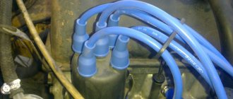
- monitor the condition of the generator windings, in particular, do not allow them to darken;
- check the contact on the control wire of the relay-regulator, both its quality and the presence of oxidation on it;
- Perform periodic voltage checks on the vehicle battery with the engine running.
Following these simple rules will allow you to increase the resource and service life of both the generator and the vehicle voltage regulator.
Results
Checking the voltage regulator relay is not a difficult task, and almost any car enthusiast with basic repair skills can handle it. The main thing is to have the appropriate tools for this - a multimeter, a power supply with a voltage regulator (although you can connect it to a battery with a charger), a 12 V lamp and pieces of wires for mounting the appropriate circuit.
If during the inspection you find out that the regulator is out of order, then it must be replaced (repair work is usually not carried out). The main thing is not to make a mistake when choosing it and purchase the part that is suitable specifically for your car.
Abnormal voltage readings on the multimeter
If the multimeter shows low voltage in the battery, the battery will simply stop accepting charge. As a result, the car may not start, the indicators on the dashboard may stop working, and troubles may arise while driving.
If the voltage is increased, there is a possibility that the level of electrolyte in the battery bank has decreased, or it has simply boiled away. Another characteristic feature may be the formation of a white coating on the walls of the body. When recharging, the battery may begin to behave unpredictably.
WHAT IS A RELAY FOR?
Every electrical circuit in a car has a relay. Why do they exist? The car contains a large number of high-power electrical elements:
■ starter; ■ horn; ■ engine cooling system fan; ■ and many others.
In the absence of a relay in the control circuit for these elements, a large current would pass through the buttons that control these elements, and this would lead to their melting. Either these buttons had to be made massive so that they could withstand such a current.
The wires leading to the control buttons also had to be used with a larger cross-section, which would have a negative impact on the price and weight of the car.
Relays exist for the purpose of controlling large currents using small currents.
PRINCIPLE OF RELAY OPERATION.
A classic relay has 4 contacts. Each relay contact has its own number:
■ 30
“
+
” constant voltage from the battery.
■ 85
“
+
” from the relay control button.
■ 86
“
—
” (ground, mass).
■ 87
“
+
” circuit going to the actuator when the relay is activated (horn, starter, etc.)
When voltage is applied to the contact 85
87
and
30
close and thus the current flows to the actuator.
When the power supply is turned off, contacts 87
and
30
open. This is the operating principle of a normally open relay.
CHECKING RELAY OPERATION.
Typically, checking a relay by most car enthusiasts is limited to checking its operation and on the basis of this a conclusion is made about the operability of the relay. A more correct verification algorithm is given below and it consists of three successive steps. If the relay passes all these stages, we can conclude that it is operational.
■ Step 1
.
Connect pin 86
(pin 3 in the diagram) to the negative terminal of the battery.
Briefly connect pin 85
(pin 5 in the diagram) to the positive terminal of the battery. Is the relay clicking?
Yes - We move on to the next verification step. No - Replace the relay.
■ Step 2
.
Measure the resistance between pins 30
and
87
of the relay. (on the diagram contacts 1 and 2) Is it infinite?
Yes - We move on to the next verification step. No - Replace the relay.
■ Step3
.
Connect pin 85
to the positive terminal of the battery and pin
86
(pins 5 and 3 in the diagram) to the negative terminal of the battery.
Measure the resistance between pins 30
and
87
of the relay. (on the diagram contacts 1 and 2). Is it less than 1Ω?
Yes - the relay is OK. No - Replace the relay.