Charging relay VAZ-2106 characteristics, malfunctions
The relay on the VAZ-2106 car is a device that serves as a switch.
Its main goal is to open and close certain sections of the electrical circuit at the moment of reaching specific indicators of non-electrical and electrical quantities. This device plays the role of a load current switch for a performer, for example, a generator, starter, fan or other consumer that consumes a large amount of energy.
The electric charging relay for the VAZ-2106 is designed as follows:
- electric magnet - a wire wound on a coil with a metal core;
- anchor - a kind of plate. Her role is contact management;
- switch (closing or breaking a specific group of contacts).
At the moment an electric current appears in the winding of an electromagnet, a magnetic electric field appears. The force of the emerging magnetic field presses the armature to the core. In turn, with the help of special pushers, the armature moves the contacts, thereby closing or opening them.
On VAZ-2106 cars, two main types of voltage regulator relays (charging relay) are used.
- Relay regulator 121.3702. New sample device. This relay is widely used nowadays, as it does not require additional settings and adjustments.
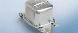
- Magnetic type electric regulator marked PP-380. An outdated sample of the device, the production of which has currently been stopped. This part is no longer used on VAZ-2106 cars.
The possibility of replacing the voltage relay is provided in such a way that there is no need for modifications in the VAZ-2106 car. This means that there is no need to interfere with the car's charging system.
Before replacing the old-style charging relay, you should check the functionality of the new one. To do this, we start the VAZ-2106 car. The engine speed should be 2,500-3,000. After this, turn off all devices that can use electricity (the ignition remains on). Using a tester, we measure the voltage at the battery terminals. It should be close to 14 V.
Diagnosing charging relay faults
- Worn generator brushes. If the length of the generator brushes of the VAZ-2106 car becomes insufficient, the charge may be lost. When diagnosing a malfunction, you should first carefully check the condition of the brushes in the generator. Their length should not be less than 12 millimeters. If it does not meet the minimum requirements, then they need to be replaced.
- The diode bridge of the generator does not work. Failure of one or more elements of the rectifier unit may cause a charging malfunction. You should use a tester to check the serviceability of all diodes.
- Circuit breakers. If there is no charging current in the VAZ-2106 car, it is worth checking the fuses. If a burnt one is found, it should be replaced.
- Alternator belt and its tension. The generator belt is made in the shape of a wedge, so it is bursting between the cheeks in the pulley. When the pulley wears out, the generator belt may slip in the cheeks. Because of this, charging problems sometimes occur. In this case, it is necessary to immediately replace the generator pulley and belt.
- Battery terminals. If there is oxidation on the battery terminals, it may prevent the battery from charging. In this case, you should clean the terminals with soda dissolved in water. This product can remove plaque. After completely cleaning the terminals from oxidation, wipe them well with a dry cloth and then lubricate them with thick lubricant.
Generator VAZ 2106
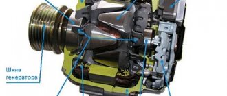
The standard VAZ generator of the sixth model refers to electronic devices with alternating current flow on a six-diode rectifier made of silicon base. This is a powerful generator, its location is on the right side of the car’s power plant, where it is located on an adjustable bracket and is connected by transmission through a generator belt to the crankshaft pulley.
The schematic diagram of the generator is posted on our Internet resource, and its design includes such basic elements of an electrical machine as a rotor, stator, 2 covers, a diode bridge of the generator and a number of other elements. The rotor of the product is equipped with an excitation winding. The rotor contains a generator bearing in a closed cage.
Replacement
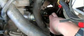
To carry out repair work we will need tools: wrenches “10”, “17” and “19”, a mounting spatula. If everything you need is present in your combat arsenal, then you can begin work.
Removing the VAZ 2106 generator must be done in the following sequence:
Application of generators.
Reasons for VAZ 2110 battery discharge
The VAZ 2107 charging scheme depends on the type of generator used in the car. To recharge the battery on VAZ-2107 (2104, 2105) cars with a carburetor engine, a G-222 type generator or similar with a maximum output current of 55A is used. On VAZ-2107 cars with an injection engine, a generator of type 5142.3771 or similar, the so-called high-energy generators, with a maximum output current of 80 - 90A is used, depending on the design. It is possible to install more powerful generators with an output current of up to 100A. All types of alternating current generators with a built-in rectifier unit (diode bridge) and a voltage regulator, made in one housing with brushes or a removable one mounted on the housing.
goes out the reasons for the loss of charging on the VAZ For
Mitsubishi Carisma Logbook The battery charging light is on, but there is charging, what is the reason
2106 checking the electrical circuit of a car, you need a simple multimeter or voltmeter. The most common causes of loss of charging voltage are:
- are low tension on the alternator belt or wear;
- generator malfunction (deterioration, malfunction of diode bridge brushes, breakage or burnout of stator or armature coils);
- voltage regulator malfunction;
- break in the charging circuit.
The most common cause of charging failure is a faulty relay voltage. In order to check its functionality, it will be enough to remove both wires from it, connect them together, and start Pri. engine provided that all other circuit elements are suitable, the voltage in the circuit will approximately reach 17 V or more. If the voltage is not necessary, then check for the presence of +12 V at the terminal, the output to the connected 15 relay-regulator. If it is missing, check the fuse responsible for the circuit and the integrity of this circuit itself.
If there is power at this terminal, then you need to check the connections in the excitation circuit of the generator. Connect a +12 V battery test lamp between the battery and the wire that is connected to relay 67 terminal of the voltage regulator. In this way, you can also check the voltage relay circuit, and check the serviceability of the generator brushes and its armature windings. If there is no voltage at the terminals, the lamps assume that the rectifier bridge is faulty.
Next, check the serviceability of the conductor from the generator to the relay. To control such a test, it is necessary to disconnect the generator from the terminal and connect it to -12 V. The glow of the control lamp indicates faulty brushes or a broken armature of the windings. If you suspect a generator malfunction, remove it from the car and perform a complete disassembly. Next, check the serviceability of each diode in the diode generator bridge, perform a continuity test of the stator coils and check for a break or burnout in the armatures. Faulty elements are repaired or replaced.
The VAZ 2106 battery charging circuit provides for the presence of a constant voltage, regardless of 13.5 to 14.3 V, depending on engine speed. However, there are times when at medium engine speeds the voltage drops “noticeably” when an additional load is turned on. If such a phenomenon occurs, it is necessary to check the tension of the generator belt and adjust it. Weak terminals on the battery contact sometimes also lead to this effect.
If the voltage at the battery terminals is higher than the specified limits, you need to check all the contacts, starting from the positive terminal of the battery to the voltage regulator-relay. If all contacts are in the relay, then the regulator must be replaced.
Timely maintenance of the electrical equipment of the car, the condition of the contacts and terminals of the battery, regular checking of the belt tension and electrolyte level in the battery will allow your car’s engine to operate for a long time and without problems, and you will avoid many malfunctions on the road.
Possible generator malfunctions, their causes and methods of elimination of the VAZ 2101 Zhiguli
- Repair manuals
- Repair manual for VAZ 2101 (Zhiguli) 1970-1985.
- Possible generator malfunctions, their causes and methods of elimination
| CAUSE | REMEDY METHOD |
| The warning lamp lights up or lights up intermittently when the vehicle is moving. | |
| Alternator drive belt slipping | Adjust the belt tension |
| Break in the connection between plug “85” of the charge warning lamp relay and the center of the generator star | Check and restore connection |
| Charge warning lamp relay misaligned or damaged | Check the relay, adjust it or replace it |
| Open circuit in the power supply circuit of the excitation winding | Reconnect |
| The voltage regulator is misaligned or damaged | Clean contacts, adjust or replace regulator |
| Worn or stuck generator brushes; oxidation of slip rings | Replace the brush holder with brushes; wipe the rings with a rag soaked in gasoline |
| Open circuit or short circuit to ground of the generator excitation winding terminals | Connect the winding leads to the slip rings or replace the rotor |
| Short circuit of one or more "positive" valves of the generator | Replace the generator rectifier unit |
| Open circuit in one or more generator valves | Replace the generator rectifier unit |
| Break in the connection between plugs “86” and “87” of the charge warning lamp relay | Reconnect |
| Open circuit or interturn short circuit in the stator winding | Replace generator stator |
| The warning lamp does not light up when the ignition is turned on | |
| Burnt out filament | Replace the lamp |
| Charge warning lamp relay misaligned or damaged | Clean contacts, adjust or replace relay |
| Open circuit in the connection between plug “87” of the charge warning lamp relay and plug “I” of the fuse box | Reconnect |
| Short circuit of one or more “negative” generator valves | Replace the generator rectifier unit |
| Short circuit of the stator winding to ground | Replace stator |
| The generator is running, but the battery is charging poorly | |
| Weak belt tension; slipping at high speeds and when the generator is running under load | Adjust the belt tension |
| The fastening of the wire lugs on the generator and battery is loose; battery terminals are oxidized; wires are damaged | Clean the battery terminals from oxides, tighten the clamps, replace damaged wires |
| Battery faulty | Replace the battery |
| The voltage regulator is misaligned or damaged | Clean contacts, adjust or replace voltage regulator |
| The battery is being recharged | |
| Poor contact between ground and voltage regulator housing | Reconnect |
| The voltage regulator is misaligned or damaged | Adjust or replace voltage regulator |
| Battery faulty | Replace the battery |
| Increased generator noise | |
| Generator pulley nut loose | Tighten the nut |
| Fan blades are bent | Align the fan or replace it |
| Generator bearings are damaged | Replace bearings |
| Interturn short circuit or short circuit to ground of the stator winding (generator whine) | Replace stator |
| Short circuit in one of the generator valves | Replace the rectifier unit |
| Brushes creaking | Wipe the brushes and slip rings with a cotton cloth soaked in gasoline. |
↓ Comments ↓
1. Technical data
1.0 Technical data 1.1 Main overall dimensions of the VAZ-2101 car 1.2 Main overall dimensions of the VAZ-21011 car 1.3 Main overall dimensions of the VAZ-2102 car 1.4 Technical characteristics of the cars 1.5 Controls and monitoring devices 1.6 Ignition switch 1.7 Interior ventilation and heating controls
2. Operation and Maintenance
2.0 Operation and maintenance 2.1. Vehicle operation 2.2. Vehicle maintenance
3. Engine
3.0 Engine 3.1 Features of the device 3.2 Possible engine malfunctions, their causes and methods of elimination 3.3 Removing and installing the engine 3.4 Disassembling the engine 3.5 Assembling the engine 3.6 Bench tests of the engine 3.7 Checking the engine on a car 3.8. Cylinder block 3.9. Pistons and connecting rods 3.10. Crankshaft and flywheel 3.11. Cylinder head and valve mechanism 3.12. Camshaft and its drive 3.13. Cooling system 3.14. Lubrication system
4. Fuel system
4.0 Fuel system 4.1. Power system 4.2. Carburetor
5. Ignition system
5.0 Ignition system 5.1 Setting the ignition timing 5.2 Gap between the breaker contacts in the ignition distributor 5.3. Checking ignition devices on a stand 5.4 Possible ignition malfunctions, their causes and methods of elimination
6. Starting and charging system
6.0 Starting and charging system 6.1. Battery 6.2. Generator 6.3. Starter
7. Transmission
7.0 Transmission 7.1. Clutch 7.2. Gearbox 7.3. Cardan transmission 7.4. Rear axle
8. Chassis
8.0 Chassis 8.1. Front suspension 8.2. Rear suspension 8.3. Shock absorbers 8.4 Possible malfunctions of the chassis, their causes and methods of elimination
9. Steering
9.0 Steering 9.1 Features of the device 9.2. Inspection, check and adjustment of steering 9.3. Steering mechanism 9.4. Steering rods and ball joints 9.5. Pendulum arm bracket 9.6 Possible steering malfunctions
10. Brake system
10.0 Brake system 10.1. Features of the device 10.2. Checking and adjusting brakes 10.3. Clutch and brake pedal bracket 10.4. Main cylinder 10.5. Front brakes 10.6. Rear brakes 10.7. Rear brake pressure regulator 10.8. Parking brake 10.9 Possible brake malfunctions, their causes and methods of elimination
11. Electrical equipment
11.0 Electrical equipment 11.1. Electrical circuit diagrams 11.2. Lighting and light signaling 11.3. Sound signals 11.4. Windshield wiper 11.5. Heater electric motor 11.6. Control devices
12. Body
12.0 Body 12.1 Features of the device 12.2. Repair of the body frame 12.3. Paint and varnish coatings 12.4. Anti-corrosion protection of the body 12.5. Doors 12.6. Hood, trunk lid, bumpers 12.7. Body glazing and windshield washer 12.8 Instrument panel 12.8. Removal and installation 12.9. Seats 12.10. Heater
13. Features of repair
13.0 Features of repair 13.1. Car VAZ-21011 13.2 Cars VAZ-21013 13.3. Car VAZ-2102 13.4 Cars VAZ-21021 and VAZ-21023
14. Applications
14.0 Appendices 14.1 Tightening torques for threaded connections 14.2 Tools for repair and maintenance of vehicles 14.3 Used fuels, lubricants and operating fluids 14.4 Basic data for adjustments and control
Understanding the reasons for charging problems on the VAZ 2106
Where is the relay located on the VAZ 21099 starter?
To check the electrical connection of a car, you need a simple multimeter or voltmeter. The most common reasons for low charging voltage are:
- The generator belt tension is too weak or too worn;
- generator malfunction (worn brushes, faulty diode bridge, broken or burnt stator or armature coils);
- voltage regulator malfunction;
- shaving in charging area.
The most common cause of charging failure is a malfunction of the voltage relay. In order to verify its usefulness, it will be enough to get rid of the grievances, unite with each other, start the engine. For the sake of understanding that all other elements of the lance are attached, the voltage in the lance is close to 17 V or more. If the voltage does not increase, then it is necessary to check the presence of +12 V at the terminal connected to pin 15 of the relay regulator. If necessary, check the lance, which confirms the lance and the very integrity of this lance.
If the food is on this terminal, it is necessary to check the connection in the generator wake-up circuit. Connect the test lamp between the +12 V battery and the wire that connects to connection 67 of the voltage regulator relay. In this way, you can check the voltage relay-generator circuit, as well as check the generator brushes and windings of its armature. If there is no voltage at the lamp pins, worry about a malfunction of the direct bridge.
Next, check the serviceability of the conductor from the generator to the relay regulator. For such a check, it is necessary to disconnect the terminal from the generator and connect it to -12 V. For the control lamp, talk about faulty brushes or broken armature windings. If a malfunction of the generator is suspected, it should be removed from the vehicle and rotated outside of disassembly. Next, check the integrity of the diode in the diode bridge of the generator, check the continuity of the stator and armature coils for damage or burnout. Faulty elements must be repaired or replaced.
The VAZ 2106 battery charging circuit transmits a constant voltage of 13.5 to 14.3 V, regardless of engine speed. However, outbursts occur when at mid-speed the engine voltage noticeably “sags” when the additional voltage is turned on. If such a phenomenon occurs, it is necessary to check the tension of the generator belt and adjust it. Weak contact at the battery terminals can also lead to this effect.
Since the voltage at the battery terminals is higher than the indicated values, it is necessary to check all contacts, starting from the positive connection of the battery to the voltage regulator relay. If all contacts are normal, then the relay regulator prompts replacement.
Keeping an eye on your car's electrical system, the contacts and terminals of the battery, regularly checking the belt tension and the level of the electrolyte in the battery will allow your car's engine to run smoothly and without problems, and you will be safe There are a lot of malfunctions in the dosage.
Relay voltage regulator VAZ generator
A voltage regulator relay (or simply a voltage relay) is a device designed to maintain the on-board network voltage received from the generator. The fact is that the generator, due to the uneven rotation of the rotor, cannot provide a uniform output voltage, since it either increases or decreases. To maintain a given voltage value, a relay regulator is used.
This device was initially produced in the form of an electromagnetic relay, the basis of which was a coil with a core and a number of small mechanisms for closing, opening and creating a certain resistance in the circuit. This type of regulator is already obsolete and is no longer produced.
The outdated type of relay has been replaced by an electronic semiconductor device. It differs from the old model in the absence of any contacts, dimensions and contents. In addition, it cannot be adjusted, therefore it is a disposable element.
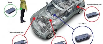
The relay is secured using studs and nuts on the car body in the engine compartment. However, modern models, for example, on the VAZ 2109, VAZ 2112, Lada Priora and Lada Kalina, have voltage relays that are attached directly to the generator brushes and form a single whole. Such elements are popularly called “tablets”.
Malfunctions of the voltage relay and their diagnosis on the VAZ 2106
During the operation of the vehicle, certain malfunctions may occur in the on-board network, which indicate a poor power supply to the equipment. First of all, car enthusiasts check the condition of the generator. It is removed, disassembled, diagnostics are carried out and the belt tension is assessed. If during the verification process it turns out that it is working, then the last thing left is the voltage regulator relay.
https://youtube.com/watch?v=a3h2HMw8MxU
The most common malfunction of the relay regulator is too little or too much charge. When the charge is low, the headlights do not work well at idle, the engine runs unstable, and the situation improves after adding speed to the crankshaft.
When the charge is high, many fuses often blow, the headlights shine too brightly, and the electrical equipment gets hot. In both cases, start measuring the voltage of the on-board network.
Start the engine and warm it up. Attach the ends of the voltmeter to the battery terminals. The voltage should be 13.5 - 14 volts. Try turning on the headlights, wipers, etc. If the voltage drops below 12 volts, the voltage relay needs to be replaced.
Replacing the voltage regulator relay VAZ 2106
To replace the voltage relay on a VAZ 2106, disconnect the battery terminal and remove the plug with wires from the old relay. After this, unscrew the fastening nuts and remove the faulty element from the studs. After this, install the new relay and tighten the nuts. Insert the plug into the sockets of the new relay and attach the battery terminal.
After installing a new element, it is recommended to check it. The fact is that such relays have the peculiarity of working properly only on one machine. This is due to the poor quality of assembly of components for our cars. Therefore, if the device readings again do not meet your expectations, return the relay to the store and ask for another one. It is quite possible that the next relay will be the one.
In addition, there is also the possibility of receiving a defective device. That is why checking the relay must be carried out.
How to check the generator relay regulator with your own hands
Having examined the device and principle of operation, you can proceed to testing. It is noteworthy that it is quite possible to check the relay regulator in an ordinary garage. To do this, you need to have a regular multimeter with a scale of up to 35 volts, a set of wrenches and screwdrivers.
- A simple method for checking the generator regulator on a VAZ 2106 assumes the following: a well-charged battery is needed for testing. To perform diagnostics, you need to start the internal combustion engine, turn on the headlights and leave the engine running for 10-15 minutes, while the engine speed does not increase above 2 thousand rpm. Next, you need to use a multimeter to measure the voltage between the battery terminals. The norm is no higher than 14 Volts and no lower than 12 Volts.
- The second test method should be used when the problem is “floating” (the voltage at the battery terminals is slightly less than 12 Volts or slightly higher than 14 Volts). In such a situation, the regulator must be checked separately by removing it. To check, use a multimeter and a 12 volt light bulb.
Having examined the regulator of the VAZ 2106 generator, you can find a pair of outputs (on the diagrams often marked with the letters B and C). The indicated contacts must be supplied with power from the battery. Two more relay contacts go to the generator brushes. A lamp is connected to the indicated contacts.
If the voltage at the outputs when power is supplied from the battery is not higher than 14 volts, the light will light brightly. If you use a multimeter to increase the voltage at the power supply outputs to 15 volts or higher, the light should go out. If this does not happen, then the regulator has failed. If the light does not light up initially, both in the first and second cases, then the relay needs to be changed.
- Replacing the VAZ 2106 generator regulator involves selecting a suitable device. It is important to immediately determine what type of device is on the generator (external regulator, internal regulator). The external regulator is located on the front left arch (in the area of the front wheel). The internal regulator is removed after removing the air filter, since the filter blocks access to the generator.
It will be useful: VAZ 2115: replacing silent blocks of the front suspension and rear beam (video)
Then the relay is carefully pulled out of the generator cover, after which the wires and contact block are removed. When removing the block, special care must be taken, since the contacts are fragile. Next, a new regulator is installed and reassembled.
- Please note that external regulators for the VAZ 2106 are almost impossible to find new for sale. We have to pay for used devices. So, the real condition of such a regulator is difficult to visually determine, that is, a check is necessary before purchasing (you can use the methods discussed above).
Regarding internal regulators, the main problem is the wires connected to the relay from the generator. Very often, when replacing, they break in the area of the contact block. If this happens, you will need to cut the block, resolder the wires, make high-quality insulation, and then glue the block back together.
To avoid such problems, when replacing the internal regulator of the VAZ 2106 generator, you need to be extremely careful, do not repair the car in the cold, since the wires break more easily in such conditions, etc.
Charging relay VAZ 2106 characteristics, malfunctions
The VAZ charge relay can be called a kind of switch that is activated at the moment when the starter, generator, etc. begins to consume more current than stated. However, it often happens that the regulator itself needs help! It is quite possible to try to diagnose the cause of the problem, both in a UAZ and a VAZ, on your own, but repairs should only be carried out by a professional. The process does not tolerate amateurism! Making a few mistakes can render the charging system completely unusable. But restoring the circuit is very difficult.
What does a relay consist of?
The charging relay has a fairly simple implementation scheme, which will certainly be understandable to those who have already encountered similar problems. Minimum elements, maximum performance of each of them. Within a few hours the diagram can be studied inside and out!
The device includes:
- an electromagnet wound on a coil with a core made of magnetic material;
- anchor - a special plate responsible for controlling contacts;
- switch - an element responsible for opening and closing contacts.
On VAZ 2106 cars, 2 types of relays are used:
- Non-contact. A relatively new unit that does not require settings or adjustments from the driver. It rarely fails and, if necessary, can be easily replaced with a similar component that is still in production today.
- Magnetic regulator. The device is an old model, which has quite a lot of complaints. It is not possible to find it on the market today, but it is quite possible to replace such a model with an updated version.
Relay interchangeability is one of the best opportunities that the company that created the VAZ 2106 could provide to drivers.
Thus, by gradually improving the components, the owner will be able to use any vehicle for a long time, the repair of which, compared to foreign equivalents, will cost a minimal amount. If you want, the VAZ 2106 can be improved somewhat. And for very real money.
Possible problems and diagnostics
There are quite a few reasons why a non-contact relay coded 702 or its magnetic equivalent will fail.
The most common ones are:
- Wear of generator brushes. Over time, the length of the brushes may decrease, which inevitably leads to a complete absence or partial loss of charge. If you notice a problem, you should definitely check the length of the brushes. It should not be less than 12 mm! If there is even a slight deviation from the specified parameter, it requires immediate replacement.
- Diode bridge problem. Burning out even a few diodes can result in a weak battery charge. Diagnostics of the bridge in a service station is mandatory!
- Integrity of fuses. Finding a fault in this system is not an easy task, but after spending a few hours, you will definitely be able to find it! The most radical measure is replacing fuses, which can be completely avoided in the vast majority of cases.
- Terminal oxidation. You can clean them yourself by using water with soda diluted in it. Just a few minutes, and the VAZ charging system will function like new.
Such problems are among the most common and occur in the vast majority of cases. If it was not possible to identify the problem on your own, it is better to contact a specialist who will probably figure out how to resurrect the charging relay.
Voltage regulator VAZ 2106 and its replacement
- the electromagnetic PP-380 was installed on the first cars, but it is currently considered obsolete;
- non-contact type with designation 121.3702. This new voltage regulator, which does not require tuning or adjustment, was used in the last years of production of the VAZ 2106 car.
Relay regulators only have a different circuit, the principle of operation is largely similar, and the connection is identical. To replace an old-style regulator with a new one, simply connect the wires to the appropriate plugs. But before replacement, you will need to check the functionality of the relay regulator.
Types of relay regulators VAZ
In recent years, a relay regulator with the designation 121.3702 was installed, which worked in symbiosis with the G-221 alternating current generator. But such a perfect device, which does not require any adjustments or additional maintenance, began to be used in the 90s. Initially, cars came off the assembly line with a PP-380 vibration regulator. So it needed adjustments, settings, and even maintenance. When working with the PP-380 regulator, you need to follow simple rules.
- Do not under any circumstances confuse the wires marked “67” and “15”. If this happens, the relay regulator will not function; its contacts located on top will be short-circuited. The result is a sharp increase in voltage at the output terminal of the generator, boiling of the battery, failure of all electricity consumers and the VAZ 2106 voltage regulator itself.
- It is not allowed to connect capacitors to the circuit of plug “67” to counteract radio interference. The contacts end up working incorrectly and as a result they are destroyed.
- It is prohibited to include any electrical energy consumers in the excitation winding circuit. Otherwise, the output voltage increases several times.
- The plugs numbered “67” and “15” cannot be connected to each other, since the output voltage increases significantly and the probability of failure of the semiconductor rectifier is very high.
- It is not recommended to remove the cover from the regulator, because dust and moisture can get into it, the contacts will begin to burn and become dirty, which will lead to improper operation of the mechanism. Installation of gaskets made from scrap materials is prohibited.
- Do not hit the regulator body, keep it clean.
- The electrical connections between the ground of the VAZ 2106 car and the device body must be reliable, with minimal resistance. If the connection is weak, then the probability of voltage increase is very high.
Checking and replacing the regulator
Before starting to diagnose the condition of the voltage regulator, it is recommended to charge the battery. To do this, remove it and, unscrewing the plugs of all compartments, let it charge from the mains for several hours. Monitor the charge level using the indicator on the charger.
After this, install the charged battery on the VAZ 2106 car and start the engine. Using the choke handle, set the engine speed in the range of 2500-3000 rpm. All consumers of electrical energy must be turned off; even the operation of LED running lights is not allowed.
Using a wide-scale voltmeter (can also be used with a digital indicator), measure the voltage at the battery terminals. The voltage value should be approximately 14.2 V. A deviation up or down is allowed, but not more than 0.1 V. If the deviation is significant, the relay-regulator must be completely replaced immediately. Just remember to check the following immediately before starting diagnostics:
- the alternator belt has normal tension;
- The VAZ 2106 regulator body has reliable contact with the car body.
If there are any shortcomings, they must be eliminated by adjusting the belt tension or tightening all the nuts that secure the regulator relay to the body. To replace the VAZ voltage regulator, you will need to perform the following steps:
- Unscrew 2 nuts from the studs;
- mark all the wires with a marker so as not to confuse them later;
- disconnect the wires from the voltage regulator;
- remove the old regulator and install a new one in its place;
- connect the wires according to the diagram;
- tighten the nuts.
Why is it necessary to repair the ignition switch?
The ignition switch of such a classic car as the VAZ 2106 has 4 operating modes, which differ in the performance of electrical functions.
- Zero mode is responsible for practically nothing, it only powers some wires.
- The first mode makes it possible to operate not only running lights, but also foglights, wiper blades and supports the operation of the car’s heating.
- The second mode is responsible for the operation of the turn signals, dashboard and ignition system.
- The third position powers the terminals.
Almost every driver may need to replace the ignition switch once. This can be explained by the fact that some drivers lose their ignition keys, but how can you start a car without keys?
Well, if we talk about a classic car, most likely, the driver of the VAZ 2106 has already dealt with the physical wear and tear of some parts, in this case we are talking about the lock cylinder. If the wires in the ignition already look somehow suspicious, then the wiring should be replaced as soon as possible so as not to lead to a short circuit.
Generator. Installation of an external relay-regulator instead of the built-in one.
For modification, it is necessary to remove and disassemble the generator. Remove the brush assembly and remove all contents from it.
So, there are 2 brushes. One of them is negative and when installing the brush holder into the housing, it shorts out to it (to the housing). Determining which one is not difficult - you can visually, or you can use a tester.
The second brush, positive, must be connected to terminal 15 (Ш) of the remote regulator relay. But, in order for power to be supplied to the relay only when the ignition is turned on, an additional normally open relay must be inserted into the circuit, for example a light or starter relay.
The general connection diagram is as follows:
Power is supplied to excitation winding 1 through relay regulator 2 only when the ignition switch is turned on. This is exactly what additional relay 3 is for.
But, we must keep in mind that such a scheme cannot be implemented on vehicles with a CAN bus due to the appearance of many errors. In addition, the charge indicator lamp on the tidy will not work. You will have to install an additional voltmeter to monitor the voltage.
Functions of electrical wiring of "six" models
Electrical wiring elements, like any other element that is responsible for the functioning of the car, fully have their own characteristics, and the wiring diagram, in turn:
- activates electrical circuits by using the VAZ 2106 ignition switch;
- connects to the battery through a fuse block;
- conducts electric current to key components.
Based on all of the above, you need to start looking for all faults with the ignition switch, because most of the responsibility lies with it. The key unit itself is not only responsible for controlling the entire ignition system in the car, but also performs a security function. It also allows the car to be towed.
Checking the electrical equipment of the UAZ if the battery charge is lost
The UAZ Patriot has two current sources to power all electrical equipment - a battery and a generator. The battery is used when starting the engine and to supply 12 V electric current to the starter and other consumers when the engine is not running. When the engine is running, the main source of current is the generator; it provides electric current to all consumers, including the ignition system, and charging the battery.
If the battery discharge warning light is on in the instrument cluster, it means that current is not flowing from the generator to the on-board network and the battery's energy reserves are being consumed. Operating a vehicle with a low battery warning light on is unacceptable, as sometimes the cause of the light coming on may be a short circuit in the wiring, leading to a fire in the engine compartment.
Stop the car, turn off the engine and determine what fault caused the warning light to come on. If the cause of the malfunction is not a short circuit, and the battery is fully charged, you can drive to the repair site without a generator, but it is better to try to fix the malfunction on the spot.
The procedure for checking the electrical equipment of the UAZ Patriot in the event of a lack of battery charge.
1. Check to see if the accessory drive belt is broken. If a break occurs, replace the alternator drive belt.
2. If the belt is intact, check and, if necessary, adjust its tension.
3. If the warning light remains on, slide off the rubber protective cover of the plus terminal of the battery. Check the wires connected to the plus and minus terminals of the battery.
4. Check the wires connected to the starter and generator. They may be torn, broken off inside the insulation, or have oxidized or unreliable contacts.
5. If there is a malfunction, correct it and start the engine. If charging current appears, you can continue driving.
6. If, after taking measures, the warning light continues to light while the engine is running, then the possible cause of the malfunction lies in the generator itself.
There may be several reasons for a generator malfunction and it is better to eliminate them in a car service center or garage, and you just have to hope that the energy reserve in the battery is enough to get to them.
In order to reduce current consumption when driving a car with a faulty generator, if possible, turn off the audio system, unnecessary lighting devices, air conditioning, heater fan, heated rear door glass, etc.
179 VAZ 2106 generator performance check Diagnostics of the generator on a VAZ 2106 car, described in subsection. “Replacing the voltage regulator” allows you to approximately calculate the malfunction of the generator if, even after replacing the voltage regulator and adjusting the tension of the generator drive belt, the battery charge indicator light is on.Caution It is prohibited to check the serviceability of the generator by disconnecting it (even briefly) from the battery while the VAZ 2106 engine is running. The resulting voltage surge will damage the generator rectifier unit.
Diagnostics of the generator on the stand allows you to calculate the suitability of the generator and the relationship between its nominal characteristics. For the VAZ-2106 generator being tested, the brushes must be well ground to the contact rings of the commutator, and the rings themselves must be clean. Place the generator on the stand and connect it as shown in the figure. 9.4. Turn on the electric motor of the stand, set the voltage at the generator output to 14 V using rheostat 5 and increase the rotor speed to 5000 min. Let the generator operate in this mode for at least 2 minutes, and then measure the output current. For a working generator, the output current must be at least 44 A. If the measured value of the output current is significantly less, this indicates a malfunction in the stator and rotor windings, a malfunction of the diodes, or wear of the slip rings and brushes. In this case, a thorough diagnosis of the windings and diode bridge of the generator is needed to determine the location of the fault. If you suspect a malfunction of the diodes of the generator rectifier unit, check the strength of the output current on a warm generator. Such diagnostics make it possible to preferably identify a malfunction of the diode bridge by a sharp decrease in the output current as the temperature of the generator increases. To warm up, let the VAZ-2106 generator run for at least 15 minutes at a rotor speed of 5000 min and a voltage of 14 V at the generator output. Next, check the strength of the output current. On a heated generator, the output current must be at least 42 A. Diagnostics of the generator with an oscilloscope allows, based on the shape of the generator's rectified voltage curve, to accurately and quickly check the suitability of the generator and calculate the nature of the defects. To measure, rotate the generator rotor at a frequency of 1500-2000 min, powering the excitation winding from the battery, but disconnect the battery from terminal “30”.
Drawing. 9.5. Shape of the generator rectified voltage curve: I - generator is OK; Ii - diode broken; III - open circuit in the diode circuit
When the diodes and stator winding are in good working order, the rectified voltage curve contains a sawtooth shape with uniform teeth (Fig. 9.5, I). If there is a break in the stator winding, or a break or short circuit in the diode bridge of the rectifier, the shape of the curve changes greatly: the regularity of the teeth is disrupted and deep depressions appear (Fig. 9.5, Ii and Iii). The suitability of the field winding and the reliability of the connection of the brushes to the slip rings of the generator can be checked on the stand, without disassembling the generator, by measuring the resistance between connector “67” and the “ground” of the generator. If the winding does not contain short-circuited turns and the brushes are well ground into the slip rings, then the resistance should be 4.2-4.7 Ohms at a temperature of 20 °C. After disassembling the generator, check the resistance of the field winding between two contact rings, which must be (4.3 ± 0.2) Ohm at a temperature of 20 ° C. In this case, it is necessary to monitor the reliability of contact between the rotor rings and the conductors attached to them.
Next, use a test lamp to check whether the winding is shorted to the base of the rotor. Connect the test lamp to a 220 V AC power supply (you can use a battery and a 12 V lamp). Connect one of the cables to the rotor body, and the second - in series to each ring. In both cases, the lamp does not have to light. If the lamp lights up, then the winding is short-circuited: the rotor needs to be replaced. The stator is checked separately after disassembling the generator.
First of all, check with an ohmmeter or with a test lamp and battery for breaks in the stator winding. To do this, turn on the test lamp to a 220 V alternating current network (you can use a battery and a 12 V lamp). Consistently connect the test lamp between all winding terminals. In all three cases, the lamp must light. If in at least one case the lamp does not light, it means that there is a break in the winding and the stator or winding must be replaced.
Next, check whether the stator windings are shorted to the base. To do this, turn on the test lamp to a 220 V alternating current network (you can use a battery and a 12 V lamp). Connect the lamp to the terminal of the stator winding, and the cable from the current source to the stator housing, but the lamp does not have to light. If the lamp is on, then a short circuit has occurred and, therefore, the stator or winding needs to be replaced. The insulation of the winding cables must be without signs of overheating, which occurs when there is a short circuit in the diodes of the generator rectifier unit. Replace the stator with such a damaged winding. Finally, you need to check with a special flaw detector whether there are any short-circuited turns in the stator winding. A good diode allows current to flow in only one direction. A damaged one may not pass current at all (open circuit) or pass current in both directions (short circuit). The short circuit of the diodes of the rectifier unit can be checked without removing the generator from the VAZ 2106 car, having previously separated the cables from the battery and the generator. You can check it with an ohmmeter or using a lamp (1.5 W, 12 V) and a battery, as shown in the figure. 9.6.
Note To simplify the fixation of parts of the rectifier unit, three diodes have a “plus” of rectified voltage on the housing. These are “positive” diodes and are pressed into one strip of the rectifier block. The other three diodes are “negative”, have a “minus” of the rectified voltage on the body and are pressed into another strip of the rectifier block or into the generator cover.
First, check whether there is a short circuit in the “positive” and “negative” diodes at the same time. To do this, connect the “plus” of the battery to terminal “30” of the generator, and the “minus” through the lamp to the generator housing (Fig. 9.6, a). If the lamp is on, then some of the “negative” and “positive” diodes have a short circuit. The short circuit of only the “negative” diodes can be checked by connecting the “plus” of the battery to the connector of the central terminal of the stator winding (12 in Fig. 9.1, this connector is not marked), and the “minus” through the lamp to the generator housing (Fig. 9.6, b) . A lamp burning means a short circuit in one or more “negative” diodes. It should be remembered that in this case, the burning of the lamp may also be a consequence of the short circuit of the turns of the stator winding to the base of the generator. However, such a malfunction is much less common than a short circuit of the diodes. To measure a short circuit only in the “positive” diodes, connect the “plus” of the battery to terminal “30” of the generator, and the “minus” through a lamp with the connector of the central terminal of the stator winding (Fig. 9.6, c). The lamp will indicate a short circuit in one or more “positive” diodes. A break in the diodes without disassembling the generator can only be detected indirectly when checking the generator on a bench by a significant decrease (by 20-30%) in the amount of current supplied compared to the rated one. If the generator windings are working properly and there is no short circuit in the diodes, then the reason for the decrease in the output current is a break in the diodes. Drawing. 9.6. Measuring circuits for the diode bridge of the VAZ 2106 generator (a - diagnostics of both “positive” and “negative” diodes; b - diagnostics of “negative” diodes; c - diagnostics of “positive” diodes): 1 - VAZ-2106 generator; 2 - control lamp; 3 - battery
Drawing. 9.4. Connection diagram of the VAZ 2106 generator for measurement on the stand: 1 - voltmeter; 2 - toggle switch; 3 - ammeter; 4 — VAZ-2106 battery; 5 - rheostat; 6 - generator
Next page""""""
- 10. 11. 12. 13. 14. 15. 16. 17. 18. 19. 20. 21. 22. 23. 24. 25. 26. 27. 28. 29. 30. 31. 32. 33. 34. 35. 36. 37. 38. 39. 40. 41. 42. 43. 44. 45. 46. 47. 48. 49. 50. 51. 52. 53. 54. 55. 56. 57. 58. 59.60. 61. 62. 63. 64. 65. 66. 67. 68. 69. 70. 71. 72. 73. 74. 75. 76. 77. 78. 79. 80. 81. 82. 83. 84. 85. 86. 87. 88. 89. 90. 91. 92. 93. 94. 95. 96. 97. 98. 99. 100. 101. 102. 103. 104. 105. 106. 107. 108. 109. 110. 111. 112. 113. 114. 115. 116. 117. 118. 119. 120.121. 122. 123.124.125.126.127.128.129.130.131. 132.133.134. 135.136.137.138.139.140.141.142.143.144.145.146.147.148. 149.150.151.152.153.154.155.156.157.158.159.160.161.162.163.164.165.166. 167.168.169.170.171.172.173.174.175.176.177.178.179.180.181.182.183. 184.185.186.187.188.189.190.191.192.193.194.195.196.197.198.199.200.
coming
VAZ 2106 car charging diagram
The VAZ 2106 charging circuit consists of quite a few small parts:
- three-phase synchronous generator with excitation winding;
- diode rectifier (combined in one generator with the housing);
- accumulator battery;
- mechanical relay regulator (voltage or electronic);
- charging indicator lamp relay;
- charging indicator lamp Generator.
The battery is driven from the wedge crankshaft via a belt drive. A rectifier built into the generator converts its current into direct current. Next, the voltage regulator-relay maintains its value in the Relay from 13.5 to 14.3 V. limits - the old type regulators worked on the mechanical principle of closing-opening contacts depending on the voltage generator. Such devices required an additional process to regulate operation.
The modern VAZ charging relay circuit 2106 contains an electronic voltage regulator, built entirely on discrete elements, and does not require additional intervention throughout its service life. However, the use of such devices requires additional safety measures. When the engine is running, it is forbidden to remove the battery from the battery terminal in order to avoid damage to the relay.
The warning lamp relay, which appears to provide an indication when the charging battery voltage is lost, is a conventional electromagnetic normally with a relay with closed contacts. One terminal of the coil relay is connected through the ignition switch to the positive terminal of the battery. The other pin is connected to +12 V of the generator. The normally closed contacts of the relay are connected to the +12 V battery (via the ignition contacts of the lock), and to the warning lamp.
When you turn the voltage of the battery key, a lamp appears on the contacts and the charging relay lights up. When the engine is running, voltage appears at the output of the generator, which is supplied to the terminals of the electromagnetic relay. When the value reaches about 7.5 V, the magnetic field of the solenoid increases so much that it attracts the armature and the contacts through which voltage from the battery is supplied to the charging lamp opens. In this case, the warning light Eliminates.
Advantages of contactless ignition
The wiring diagram may be characterized differently. Contactless ignition is a popular type of tuning of classic car models, and the VAZ 2106 is no exception. This type of ignition has no disadvantages. The main advantage is saving gasoline, the engine runs as cleanly as possible, and starting in winter is smoother, car acceleration becomes more comfortable. But the main advantage is the smooth operation of the engine.
It is important to know that the smoother the mechanism, the VAZ engine, operates, the further you can drive this car. And if you know what the circuits are responsible for, then you can repair the main parts yourself.
The wiring diagram of the VAZ 2106 is the same, except for some elements. The sensor here is pulsed; it creates oscillations that are sent to a transistor switch. Due to this supply, other impulses enter the system.
The VAZ 2106 diagram is not as complicated as it seems. There are plenty of other complex surprises in the car, but this is certainly not the wiring diagram. You need to know and understand how important it is to understand what the electrical circuit of a VAZ is and what it affects, and also whether there are any similarities with other models, for example with the VAZ 21063. And no matter how old the car is, what year it is or the century it was produced, information about the car will always be up to date.
The electrical circuit of a VAZ may be identical to its other models, as well as other elements and mechanisms, for example, an engine circuit. It’s convenient that spare parts for such cars are sold at every car market, this applies to all electrical equipment. In classic cars, it is very easy to remember what an electrical circuit is, because its analogues are quite common, so in all “classics” the electrical wiring elements can be identical. You shouldn’t be afraid of such machines; all the elements here are clear to the common Russian person. Therefore, many people do not buy new cars, but tune old units and actively use them for many years.
Tips and tricks
A common culprit for malfunctioning regulator relays may be oxidation of its terminals. This oxidation results in significant voltage loss. In this case, it is necessary to thoroughly clean the contacts and recheck. The voltage reading at the contacts should be similar to those given by the battery itself, that is, there should be no noticeable losses. Reduced voltage at the contacts indicates that they should be cleaned, and the regulator itself is often in working order. After cleaning, the terminals can be additionally treated with special chemicals that prevent further oxidation.
Finally, I would like to add that the cost of the regulator relay is not high. One of the surest ways would be to replace it with a new element if malfunctions are detected in its operation. Moreover, integrated relay regulators are a part in a monolithic housing that cannot be disassembled for repairs. Savings on this device are not justified, since rapid battery failure or a significant reduction in battery life will entail more serious costs when it is necessary to replace the battery.