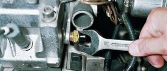
Connecting a multimeter to the oxygen sensor before testing
To diagnose the oxygen sensor, it is recommended to use a professional multimeter (it allows you to get the most accurate results), but a regular tester will do.
Before performing a lambda probe test, you must first locate it. On many older vehicles, the sensor was installed on or near the exhaust manifold. Modern cars often use two sensors - one installed in the exhaust manifold area, and the second after the catalyst. Make sure which sensor you need to check.
If you have two or more oxygen sensors, you need to understand exactly which one has the problem. Usually, if the computer shows a malfunction of sensor No. 1, we are talking about what is installed on the intake manifold. And device No. 2, as a rule, is installed after the catalytic converter. In any case, refer to the instruction manual to avoid errors
Pay particular attention to this issue if your car has a V-twin engine. Very often they use 4 lambda probes, so it is very easy to confuse them
If two or more wires are connected to the sensor under test, it is necessary to determine which of them is the signal wire. This can only be found in the car repair instructions or on specialized forums on the Internet.
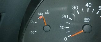
- Before you start checking the oxygen sensor with a multimeter, you need to warm up the car engine to operating temperature. To do this, you can carry out work after a 20-minute drive or wait until the engine warms up at idle speed.
- Stop the engine and switch the multimeter to DC mode (DCV) on o.
- If you are checking the sensor near the catalytic converter, jack up the vehicle and securely support it by blocking the rear wheels.
- Be careful when connecting the device. The exhaust manifold and pipes are very hot. Be careful not to get burned and keep multimeter probes away from hot surfaces.
- Connect the red probe of the tester to the signal wire of the sensor, and the black probe to ground on the engine (more modern lambda probes use at least two wires). If your car uses a heated oxygen sensor, make sure that you are connecting to the signal wire (there can be two to four wires in the connector).
To connect the multimeter probe to the wire, you can pierce it with a needle. Another option is to connect to the back of the connector using a paper clip. In some cases, it is difficult to connect to the wire through the connector. In fact, we don’t need a connector; we can connect to the lambda probe itself.
If you pierced the wire with a needle, do not forget to remove it after taking measurements and insulate the damaged area with electrical tape. Otherwise, moisture will enter the wire and corrosion may develop.
How to properly check a lambda probe with a multimeter with video
How to check the functionality of a lambda probe
A lambda probe is designed to analyze vehicle exhaust gases for the amount of oxygen and on modern cars is installed together with the so-called catalyst. An excess of this gas in the air-fuel mixture does not bode well for your car, because the operation of the catalyst directly depends on oxygen. How to check the lambda probe for serviceability with a multimeter? Let's talk about this further.
What is a lambda probe
This is a fairly simple exhaust gas analysis device based on the galvanic effect. It is usually located in the exhaust manifold. On some cars, for example, Lada Kalina, two specific oxygen sensors are installed. It has been noted that the condition of the device is directly related to fuel consumption.
Based on the readings of the oxygen sensor, the engine management system adjusts the composition of the combustible mixture if it becomes leaner. The presence of oxygen changes the electrical potential difference in the exhaust gases, and these changes are detected by the device.
Oxygen sensors from different cars
The lambda probe can only operate in a certain temperature range, so it has a built-in thermal element that turns on when the engine starts.
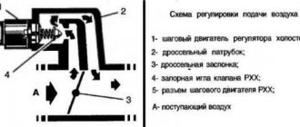
The oxygen sensor circuit is as follows:
Cross-section of oxygen sensor
Symptoms of a problem
The following symptoms indicate a malfunction of the oxygen sensor:
- The on-board computer reports an excessively rich mixture if there is no reason for this.
- Slow sensor response to changes in mixture composition.
- Misfires.
- Problems with the power supply system.
- External damage to the sensor housing.
- The engine behaves unsteadily at low speeds.
- The car's acceleration dynamics deteriorate.
- The catalyst is heating up.
Checking the oxygen sensor with a multimeter
Diagnostics of a lambda consists of monitoring the voltage of its signal output using a scanner or tester. By changing the quality of the mixture, you can track changes in the readings of the oxygen sensor, which will ultimately give a diagnosis about the serviceability or unsuitability of the latter. But the errors that the ECU shows you may turn out to be a hoax. What can you do, sometimes electronics make mistakes.
To check the oxygen sensor with a multimeter, the engine must be running and warmed up. The crankshaft revolutions according to the tachometer readings should not exceed 3000 per minute. Next, one of the probes of the tester is connected to the probe output, and the other to the “ground” of the car, and with the engine running, an imitation of changes in the composition of the combustible mixture in the cylinders begins. With a working probe, voltage readings will vary from 0.2 to 0.9 volts.
The multimeter is connected to the lambda probe according to this diagram
You can simulate a change in the air-fuel mixture by injecting a small amount of gasoline into the intake manifold or removing the hose from the fuel pressure regulator. In this case, the readings of the device should increase sharply.
How to ring and check the probe (video)
What to do if a breakdown is detected
If the tester readings are 0.4-0.5 and there is no response to changes in the position of the accelerator pedal, the oxygen sensor should be replaced. If there is no voltage at all, check visually and ring the wires going to the probe.
The lambda probe can be compared to the first violin of an orchestra - its condition seriously affects the behavior of the engine and the car as a whole. This part is very capricious, and due to the use of not very high-quality fuel, it will not be long in coming with a breakdown, one of the unpleasant consequences of which will be a sharp increase in the toxicity of exhaust gases.
Audi A6 AmethystGrau 2.6 › Logbook › Lambda probe diagnostics.
This weekend I decided to check the lambda probes (ABC 2.6 engine), there is nothing difficult to check. There were no special reasons for checking (no errors according to VAGCOM, consumption in the city is 13.5 liters), the diagnostics were carried out for a more complete understanding of the condition of the lambda probes.
The tools you will need are a multimeter and an oscilloscope.
Part 1 theory or how it should be.
After reading various information on the design, operation and testing of lambda probes, I developed a testing methodology.
Here are interesting, in my opinion, links on this topic:
So, let's start with a 2.6 liter V-shaped ABC engine. in each of the two exhaust manifolds before the catalyst there is a Bosh 078 906 265 A lambda probe.
To make checking more convenient, you need to do the following:
1.
remove the top decorative cover of the engine,
2.
disconnect the crankcase ventilation pipes,
3.
remove the intake resonator (the entrance to the throttle body from the crankcase ventilation at idle must be plugged, otherwise we will get air leaks)
4.
remove the rubber air duct from the filter to the resonator.
Then we see the following picture...
1. signal wire of the right lambda 2. signal wire of the left lambda 3. heating of the right lambda 4. heating of the left lambda 5. a convenient place to take the contact for ground 6. fuel pressure regulator pipe 7. injector power supply.
We will need all this to check the functionality of the lambdas.
We start by checking the integrity of the heating of the lambda probes, in the photo with the numbering of elements No. 3 and No. 4, for cold resistance between the contacts - 4.5 - 5.5 Ohms.
Next, remove the protective rubber from the signal wire chip.
We warm up the car to operating temperature, do not turn off the lambda probes during tests.
Part 2 Checking with a multimeter.
A Uni-T UT50 multimeter was used for testing.
1.
We set the multimeter to measure constant voltage, range 2 volts.
2.
connect the minus to the ground (point No. 5 in the photo with the numbering of the elements) plus to the signal chip (No. 1 or No. 2 in the photo with the numbering of the elements).
3.
We take measurements at engine idle speed. On a working lambda probe, the voltage should constantly change from 0.1 volt to 0.9 volt. My values: right - from 0.11 to 0.86 volts, left from 0.13 to 0.84 volts.
4.
We measure in transition mode (periodically gas up to 3500 and release), the values should change frequently. My values: right - from 0.07 to 0.85 volts, left from 0.07 to 0.86 volts.
5.
We take measurements when the mixture is lean (we turn off the fuel supply to one of the cylinders by pulling out the injector power supply chip on the block head from which we are taking readings, after the measurement we connect the injector back), a value in the region of 0.1 volts should appear on the tester. My values: right - 0.067 volts, left 0.067 volts.
6.
We take measurements with an enriched mixture (disconnect the vacuum tube from the fuel pressure regulator, No. 6 in the photo with the numbering of the elements, and plug it so that a leak does not form). Ideally, we should see 0.9 volts on the tester. My values: right - 0.89 volts, left 0.89 volts.
Having carried out this check, we can tell whether the lambda probe is working according to the voltage range or not.
My measurements showed that the lambda probes are alive and working quite correctly, the only drawback of testing with a multimeter is that there is no way to estimate the switching speed
, it should not be more than 0.2-0.3 s.
Part 3 Checking with an oscilloscope.
The principle of operation of the lambda probe
Connection diagram and pinout of VAZ power window button
As you know, at present, no methods have yet been invented to increase the efficiency of a technical device to 100%. A car engine is no exception - in this complex unit there are many components in which energy losses occur. In particular, combustion of the air-fuel mixture in the cylinders does not occur completely, as evidenced by the presence of oxygen and hydrocarbon residues in the exhaust gas.
So, the lambda probe is precisely a sensor whose task is to determine the chemical composition of the exhaust. And to be more precise, the oxygen content in it. Normally, this figure should be in the range of 0.1-0.3%. An increase in this value will indicate an over-enriched mixture, which is just as bad for an internal combustion engine as running on a lean fuel assembly.
In most cases, the lambda probe is installed at the end of the exhaust system, before and after the exhaust manifold (it should be noted that instead of a conventional muffler, in such cases there is a modified version of it - a catalytic converter).
Of course, progress does not stand still - the design of the lambda probe is constantly being improved. The two-channel arrangement, as it is easier to manufacture, is typical for economy-class vehicles, as well as cars produced since the 80s of the last century. Currently, broadband-type systems predominate - such a lambda probe has a more positive effect on engine performance, since it can determine the composition of the exhaust with much greater accuracy.
If we list what the lambda probe in a car affects, it turns out that improving the quality of the fuel assembly is not an end in itself. Thanks to more efficient combustion of the mixture, it is possible to significantly increase the overall resource of the power unit, achieve a noticeable reduction in fuel consumption, and also solve the problem of unstable engine operation at idle.
If we look in more detail at how the lambda probe works, it turns out that it cannot generate a uniform signal, since the very principle of operation of the power unit is based on generating a non-uniform number of cycles per unit of time. So it can be argued that the oxygen sensor, in general, reacts to the lack of stability in the functioning of the engine, and notifying the on-board computer about this is the main task of this device.
Simply put, oxygen sensors send data in real time to the ECU (or rather, to the on-board computer unit that specializes in controlling the operation of the fuel system), and this data is analyzed there. It consists of averaging the information received and comparing the result with the reference value. As such, it is generally accepted to consider a stoichiometric air-fuel mixture, in which 14.7 volume parts of atmospheric air fall to 1 volume part of fuel. This ratio is denoted by the letter λ and is taken as unity. If lambda (this is the answer to the question why the device is called a lambda probe) is less than one, the mixture is enriched, that is, the volume fraction of the fuel is greater than one. Otherwise, they talk about a depleted fuel assembly.
The ECU adjusts the operation of the fuel system so that the coefficient λ is always equal to unity, favoring the most efficient combustion of fuel and increasing engine efficiency to the maximum possible value.
If you turn off the lambda probe, even with an ideally tuned fuel assembly supply mechanism, it will go astray over time. Unoptimized fuel combustion results in the following unpleasant moments:
- overheating of the power unit;
- faster wear of all exhaust system components, including the catalytic converter;
- increased consumption of technical fluids (oil, fuel, coolant);
- rapid burning of valves, pistons, rings;
- a noticeable decrease in engine power (thrust) in all modes.
This is why it is so important to maintain oxygen sensors in good condition.
Oxygen sensor lambda probe, how it affects the composition of the fuel mixture
After gasoline combustion, the gases enter the exhaust manifold, where an oxygen sensor is located in front of the CO gas catalyst. It takes information about the qualitative characteristics of the exhaust, in particular the amount of residual oxygen in it compared to the O2 content in the atmospheric air.
This indicator is extremely important, since with its help the computer calculates what is the optimal ratio of fuel and oxygen to form a combustible mixture under current loads, for the highest engine efficiency.
Installing a second lambda probe after the catalyst allows the computer to make more accurate calculations, but this is very rare these days.
It is worth noting that all calculations are based on one important indicator - the effective combustion of one part of the fuel can provide 14.7 parts of oxygen.
How to check a lambda probe with a multimeter
Lambda probe oxygen sensor
In the operating instructions for all brands of cars, checking the lambda probe is mainly limited to measuring the voltage values it produces in various engine operating modes using a digital or dial multimeter.
The technical serviceability of the probe should be checked in the following cases:
- increased fuel consumption;
- the appearance of spontaneous jerking of the car in motion;
- unstable motor operation;
- increase in exhaust toxicity standards;
- after 5-10 thousand kilometers.
The principle and procedure for checking the probe on all car models is the same; depending on the type of probes used, their location and operating voltages may differ. So, on VAZ 2114 or earlier 2110 models, three-wire lambda probes can be located in different places in the exhaust system.
Let's consider the test procedure using a typical example of a BOSH probe used on Audi 80 or Audi 100 cars.
Typically, the cause of lambda probe failure is a malfunction of the filament circuit or a decrease in the sensitivity of the tip. The integrity of the filament coil and wires can be “ringed” with an ohmmeter by connecting the ends of the device to the terminals of the two white wires of the probe - contacts 3-4 of the connector (in some types - white and brown wire), which must first be disconnected from the block. The coil resistance must be less than 5 ohms.
The sensitivity of the tip may be impaired due to excessive coating of its working surface with soot, gray deposits or lead deposits, as determined by visual inspection. If such defects are present, the probe must be replaced. To check the thermoelectric parameters of the probe, connect the ends of a dial or digital voltmeter to contacts 1-2 of the connector or clamps of the black and gray wires of the lambda probe. The check must be carried out with the engine running and warm.
You can qualitatively assess the performance of the oxygen lambda probe using a voltmeter
Set the engine speed to 3000 and check the voltmeter readings at the 2V limit. The device should show a voltage of about 0.55V. By pressing and lowering the gas pedal, sharply increase and decrease engine speed. In this case, the readings of the device should accordingly increase to 0.8-1V or decrease to 0.4V and below. Dynamic changes in the device readings within the specified limits indicate the normal condition of the probe. The absence of oscillations or more sluggish oscillations of the instrument needle within smaller limits indicate the need to replace the probe.
Thus, using a voltmeter you can qualitatively assess the performance of the oxygen lambda probe. A more accurate characteristic of the sensitivity of the sensor is determined using an oscilloscope.
We will answer your questions for FREE regarding deprivation of rights, road accidents, insurance compensation, driving into the oncoming lane, etc. Daily from 9.00 to 21.00
Moscow and Moscow region
St. Petersburg and Leningrad region
Free call within Russia 8-800-350-23-69 ext.418
Oxygen sensor lambda probe, causes of breakdowns and what threatens the car during operation
The causes of breakdowns of the oxygen sensor include:
- Penetration of various process fluids and dirt into the housing.
- Increased lead content in fuel.
- Using fuel with a high octane number, which often leads to overheating of the lambda probe components.
- Poor quality fuel.
This can lead to unpleasant consequences, namely:
- Reduced power.
- Jerks in movement.
- Floating engine speed.
- The appearance of excessively polluted exhaust gases.
- Incorrect operation of the catalyst.
- Incorrect injector operation.
- High fuel consumption.
- On cars with automatic transmission, gear shifting occurs with tapping and jerking of the car.
Checking the serviceability of the lambda probe
To check the functionality of the oxygen sensor, you should visually assess its condition, and also measure the voltage generated by the regulator at different engine speeds.
Visual inspection
When checking the lambda probe, you should evaluate the integrity of the device body and connecting wires, as well as the condition of the connection connectors.
The presence of traces of soot on the sensor indicates a failure of the lambda probe heater and excessive enrichment of the fuel mixture. This leads to distortion of the readings of the control device.
A shiny coating on the working part of the oxygen regulator means an excess lead content in the fuel used. You should think about changing the gas station, otherwise you will need to replace the catalyst in the near future.
Gray or off-white deposits on the lambda probe housing appear when using the wrong type of engine oil, as well as after incorrect use of various fuel additives.
Checking the sensor with a multimeter
To check the lambda probe, the multimeter must be switched to voltage measurement mode. The negative probe is attached to the engine body, and the positive probe is connected to the signal wire of the oxygen regulator. The check is performed with the engine running and warmed up to operating temperature.
When the engine is operating at 3500 to 3000 rpm (according to the tachometer), a working oxygen sensor should operate every second and generate a voltage of 0.2–1 volts. When simulating changes in the saturation of the fuel-air mixture, the multimeter readings should increase sharply. When closing the throttle valve, the voltage at the sensor should tend to zero.
Note! A change in the composition of the mixture during testing can be simulated by injecting a small amount of gasoline into the intake manifold or removing the hose from the fuel pressure regulator.
If, during all manipulations, the voltage on the sensor is stable at 0.45 volts, the lambda probe is faulty.
The procedure for checking the oxygen regulator using a multimeter is presented in the following video:
Checking the lambda probe with an oscilloscope
An oscilloscope allows you not only to check the serviceability of the regulator, but also to evaluate, based on the amplitude characteristics, the wear of the working regulator, which leads to deterioration in engine performance, but is not detected by the car’s electronic control unit.
The check is performed with the engine warm and idling. A normally operating lambda probe under such conditions shows a sinusoidal voltage diagram with a constant step within 0.1–0.8 volts.
For an oxygen sensor that is on the verge of failure, when checking, the signal amplitude drops to zero. In most cases, this mode of operation of the regulator is determined by the vehicle’s on-board electronics, and the CHECK ENGINE control icon lights up on the dashboard.
However, an oscilloscope helps diagnose lambda probe faults that are not visible to the car's self-diagnosis systems. Such cases include “freezing” of the control signal without the voltage values going beyond the operating range. In fact, the sensor does not function correctly, but the ECU continues to take its readings into account when controlling the injection system.
Checking the sensor using the ELM327 adapter
You can check the functionality of the lambda regulator yourself using the ELM327 USB OBD II universal diagnostic scanner. This adapter is compatible with most modern European, American and Asian cars.
Note! ELM327 is suitable for diagnosing VAZ cars with ECU firmware BOSCH 7.9.7 and ME73, as well as for checking injection GAZ cars.
The device reads readings through the vehicle's diagnostic connector and displays the result on the screen of a laptop or tablet with pre-installed software (for example, the Torque Pro utility).
The visibility of graphical information is similar to that of an oscilloscope, and the convenient user interface does not require special skills in working with diagnostic equipment.
The principle of working with the ELM327 adapter is presented in the following video:
- When do you need to change the rear pads on Largus?
- How to prepare and paint a car at home
- How to change the fuel filter on Kalina
- Which sealant is best for the engine?
Checking the oxygen sensor using an oscilloscope.
Checking the oxygen sensor using an oscilloscope.
The oxygen sensor is installed in the engine exhaust gas stream and serves to determine the presence of oxygen in the exhaust gases.
When the engine runs on a rich fuel-air mixture, the level of oxygen in the exhaust gases is reduced, and the sensor generates a high-level signal with a voltage of 0.65...1.0V. When a high level signal is received from the oxygen sensor, the engine control unit begins to reduce the duration of fuel injection, thereby depleting the fuel-air mixture. When the engine runs on a lean fuel-air mixture, the level of oxygen in the exhaust gases is increased, and the sensor generates a low-level signal with a voltage of 40...200mV. When a low level signal is received from the oxygen sensor, the engine control unit begins to increase the duration of fuel injection, thereby enriching the fuel-air mixture. Thus, based on a signal from the oxygen sensor, the engine control unit adjusts the duration of fuel injection so that the composition of the fuel-air mixture is as close as possible to stoichiometric (ideal air/fuel ratio). A working oxygen sensor begins to work only after the sensing element has warmed up to a temperature of at least 350°C. There are one-, two-, three- and four-wire two-level BOSCH zirconium oxygen sensors. Single- and two-wire oxygen sensors are installed in the engine exhaust manifold as close as possible to the exhaust valves of the gas distribution mechanism and are heated to operating temperature due to the high temperature of the exhaust gases. Three- and four-wire oxygen sensors are heated to operating temperature by a built-in electrical heating element and can be installed at a considerable distance from the exhaust valves of the engine timing mechanism.
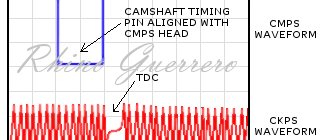
Under the condition of combustion of a stoichiometric fuel-air mixture, the voltage of the lambda probe output signal is 445…450mV. But the distance from the exhaust valves of the engine gas distribution mechanism to the location of the sensor and the significant reaction time of the sensitive element of the sensor lead to some inertia of the system, which does not allow continuously maintaining the stoichiometric composition of the fuel-air mixture. In practice, when the engine is operating at a steady state, the composition of the mixture constantly deviates from the stoichiometric one in the range of ±2...3% with a frequency of 1...2 times per second. This process is clearly visible in the voltage oscillogram of the oxygen sensor output signal.
Voltage oscillogram of the output signal of a working BOSCH oxygen sensor. The engine is idling. The signal switching frequency is
Checking the sensor output signal.
The engine control unit measures the voltage of the oxygen sensor output signal relative to the signal “ground” of the sensor. The signal ground of two- and four-wire BOSCH oxygen sensors is output through a separate wire (gray wire coming from the sensor) to the sensor connector. The signal ground of one- and three-body BOSCH oxygen sensors is connected to the metal body of the sensor and, when installing the sensor, is automatically connected to the ground of the vehicle through the threaded fastening of the sensor. The signal “ground” of the oxygen sensor, output through a separate wire to the sensor connector, is in most cases also connected to the “ground” of the vehicle. There are engine control units where the signal ground wire of the oxygen sensor is connected not to the vehicle ground, but to a reference voltage source. In such systems, the engine control unit measures the voltage of the oxygen sensor output signal relative to the reference voltage source to which the oxygen sensor signal ground wire is connected.
To view an oscillogram of the voltage output signal of the oxygen sensor, the oscilloscope probe connector must be connected to any of the analog inputs No. 1-4 of the USB Autoscope II, the black alligator clip of the oscilloscope probe must be connected to the ground of the engine of the vehicle being diagnosed, the probe probe must be connected in parallel to the signal output of the sensor (black wire coming from the sensor).
Connection diagram to the BOSCH oxygen sensor (based on zirconium oxide). 1 – connection point for the black alligator clip of the oscilloscope probe; 2 – connection point for the oscilloscope probe.
In the “USB Oscilloscope” program window, you need to select the appropriate display mode, in this case “Control => Load user settings => Lambda”.
When the lambda probe warms up to operating temperature, its output electrical resistance is significantly reduced, and it acquires the ability to reject the reference voltage coming from the engine control unit through a resistor with a constant electrical resistance. In most engine control units, the reference voltage is 450mV. Such an engine control unit considers the oxygen sensor ready for operation only after, due to warming up, the sensor acquires the ability to reject the reference voltage in the range of more than ±150...250mV.
Voltage oscillogram of the output signal of a working BOSCH oxygen sensor. Starting an engine warmed up to operating temperature. The time it takes for the lambda probe to warm up to operating temperature is
The reference voltage on the oxygen sensor signal wire on some engine control modules may have a different value. For example, for control units made by Ford it is 0V, and for engine control units made by Daimler Chrysler it is 5V.
Typical faults.
A low switching frequency of the oxygen sensor output signal indicates an increased range of deviation of the fuel-air mixture composition from stoichiometric.
Voltage oscillogram of the output signal of a faulty BOSCH oxygen sensor. The engine is idling. The signal switching frequency is underestimated and amounts to
A decrease in the switching frequency of the oxygen sensor output signal can be caused by an increased transition time of the probe output voltage from one level to another due to aging or chemical poisoning of the sensor. A malfunction can lead to an increase in engine speed at idle and a loss of engine “acceleration response.”
The service life of the oxygen content sensor in the exhaust gases is 20,000…80,000 km. Due to aging, the electrical output resistance of the oxygen sensor decreases at significantly higher sensing element temperatures to a value at which the sensor becomes capable of rejecting the reference voltage. Due to the increased output electrical resistance, the output voltage swing of the oxygen sensor signal decreases. An aging oxygen sensor can easily be identified by the voltage oscillogram of its output signal at engine operating conditions when the flow and temperature of the exhaust gases decrease. This is idle and light load mode. In practice, an aging oxygen sensor still works when the car is moving, but as soon as the engine load decreases (idling), the signal swing quickly begins to decrease until the oscillations disappear.
Voltage oscillogram of the output signal of a faulty BOSCH oxygen sensor. The engine is idling. There is no switching of the output signal.
The output voltage of an aging oxygen sensor when the engine is idling becomes almost stable, its value becomes close to the reference voltage of 300...600mV.
Checking the lambda probe at home step by step instructions
- The first thing to do is to visually inspect the sensor for integrity. Then make sure the ignition timing is correct and check the voltage in the on-board network. You should also exclude the possibility of a faulty injection system, which is directly related to the CO content in the exhaust gases.
- Next, increase the amount of gasoline in the mixture.
- We disconnect the oxygen sensor from the block and connect it to our voltmeter.
- We increase the turnover to 2,500 thousand.
- Using a device for enriching the fuel mixture, we artificially increase the gasoline content in it. This must be done in such a way that the engine speed is reduced to 200 rpm. If your engine is equipped with electronic injection, then it will be quite simple to remove the vacuum tube from the pressure regulator and install it in the line.
- If the device shows a voltage of 0.9 V, the oxygen sensor is working. If the voltage is below 0.8 V, and the response of the device is very slow, the lambda probe will need to be replaced.
Lean oxygen sensor test
Using a vacuum tube, it is necessary to simulate air leakage if for 1 second. the voltmeter readings will decrease by 0.2 V - the oxygen sensor responds correctly. Otherwise, when the readings are higher or the device responds very slowly, you need to replace the sensor.
Lambda probe dynamic mode test.
- Connect the sensor to the connector.
- Connect in parallel to the device connector.
- Restore normal system operation.
The engine should operate at a speed of ~ 1,500 thousand, the device should show 0.5 V, but if your indicators are different, you will have to change the oxygen sensor.
If your sensor fails any of these tests or there are any interruptions (violations) in its operation, replace it without unnecessary delay. If the lambda probe turns out to be serviceable, continue searching until you find the true cause of the malfunction.
Popular:
Lambda for Toyota Camry 40
Depending on the oxygen content of the exhaust gases, the sensor induces a voltage from 0.1 V (high oxygen content, lean mixture) to 0.9 V (low oxygen content, rich mixture). Based on this data, the ECM changes the opening time of the fuel injectors and changes the fuel ratio in the fuel mixture.
| To access the rear oxygen sensor connectors, you must remove the front seat. |
Checking the functionality of the oxygen sensor on six-cylinder engines.
| EXECUTION ORDER |
| To check the oxygen sensor, disconnect the electrical connector from the sensor and connect an ohmmeter to the +B and NT contacts of the sensor connector. The sensor resistance should be in the range of 11–17 Ohms. On models with four-cylinder engines, the oxygen sensor is connected with one wire. On models with six-cylinder engines with an oxygen sensor heater, the sensor is connected to a four-pin connector. Later models with four-cylinder engines have two oxygen sensors, and models with six-cylinder engines have three oxygen sensors. Block 1 sensor 1 and block 2 sensor 1 are located in front of the catalyst, and block 1 and sensor 2 are located after the catalyst. On models with six-cylinder engines, the front seat must be removed to access the rear oxygen sensor electrical connector. |
| Check the condition of the oxygen sensor heater electrical circuit. When the ignition is turned on, there should be a voltage of 12 V at the connector contacts (See table “V6 engines 1992 and 1993”, “V6 engines from 1994”) . |
| Check the voltage induced by the oxygen sensor. Connect one wire of the millivoltmeter to the electrical connector of the oxygen sensor, and connect the second wire to ground. Check the voltage generated by the oxygen sensor on the contacts (See table “Four-cylinder engines”, “Six-cylinder engines 1992 and 1993”, “Six-cylinder engines since 1994” ). |
| The magnitude of the signal induced by the oxygen sensor on a cold engine is from 0.1 to 0.2 V, and after warming up the engine it ranges from 0.1 to 0.9 V. |
| On 1992 and 1993 models. warm up the oxygen sensor to operating temperature and connect a dial voltmeter to contacts VF1 and E1 of the control connector. |
| On six-cylinder engines, connect a dial voltmeter to contacts VF1 and E1 and contacts VF2 and E1 to check the functionality of the oxygen sensor (See Fig. Checking the functionality of the oxygen sensor on six-cylinder engines ). |
| Start the engine and increase its speed to 2500 rpm for 2 minutes and then close the TE1 and E1 contacts of the control connector with an additional wire. Check that the voltmeter needle fluctuates 8 times in 10 seconds. |
| To replace the oxygen sensor, remove the ground wire, raise the car, disconnect the connector from the sensor and unscrew the oxygen sensor. |
V6 engines 1992 and 1993
| additional | black/orange wire (+) |
| oxygen sensor | brown wire (-) |
| main number 1 | not used |
| main number 2 | not used |
V6 engines since 1994
| block 1 sensor 1 | black/orange wire (+) brown wire (-) |
| block 2 sensor 1 | black/orange wire (+) brown wire (-) |
| block 1 sensor 2 | black/orange wire (+) brown wire (-) |
Four-cylinder engines.
| main oxygen sensor | white wire |
| additional oxygen sensor | red/blue wire |
Six-cylinder engines 1992 and 1993
| main number 1 | white wire |
| main number 2 | red/blue wire |
| additional oxygen sensor | white wire |
Six-cylinder engines since 1994
| block 1 sensor 1 | white wire |
| block 2 sensor 1 | red/blue wire |
| block 1 sensor 2 | black wire |
Source:
Features of operation and design of the lambda probe
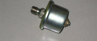
The design of the probe is reminiscent of a spark plug and consists of an iron body with edges and threads for screwing into the exhaust system manifold housing. An O-ring over the thread ensures a tight seal. The body contains a sensitive ceramic hollow tip made of zirconium dioxide with platinum coating on the inner and outer surfaces.
The outer surface of the tip, protected from mechanical damage by a screen with holes, is placed in the exhaust gas flow, and atmospheric air enters the inner surface. When the working temperature of the tip reaches 300-3500C, due to the difference in oxidative reactions between the surfaces, a potential difference arises, which is brought out using a current collector.
The ceramic insulator and sealing collar ensure reliable fastening of the connecting wires and hold the filament spiral in the tip cavity. The spiral, designed to quickly heat the tip to operating temperature, is not present in all types of probes.
An oscilloscope is needed to check the functionality of the lambda probe
Therefore, there are one-, two-, three- and four-wire probes, depending on the presence of a heater, the power supply circuit to it and the signal voltage pickup. Almost all modern car models are equipped with heated probes. Single and two-wire types of probes are found on older versions of Golf 3 or Passat B3.
How to check the throttle position sensor This diagnostic is not difficult
- When idling, increased (sometimes excessive) revolutions are observed;
- When the transmission is shifted into neutral, the engine immediately stalls;
- Idle speed is unstable (drivers call it floating);
- When accelerating (either from a standstill or already in motion), jerking is observed;
- The dynamics are noticeably worsening.
- Oxidation of contacts. In principle, this cannot be considered a breakdown - just a temporary hindrance. The sensor is removed, a cotton swab is soaked in WD-40, all terminals are wiped, the device is put in place;
- The next option is that when moving the slider, the track (spraying) was erased. For this reason, the TPS did not increase the voltage at the output;
- The design of the said slider includes a moving core. When one tip is damaged, burrs are scratched on the substrate, which damage the remaining ones. The track layer with the slider loses contact, which leads to engine malfunctions.
- To facilitate access to the desired unit, the air ducts from the air filter are removed from the branch pipe related to the throttle assembly;
- The crankcase ventilation hoses are also removed from the pipe leading to the cylinder head cover;
- Directly from the sensor itself, by pressing the lock, the block with the wiring harness is disconnected;
- Testing is transferred to a voltmeter. Its negative terminal is connected to the minus of the engine, the positive terminal is connected to the block at the output indicated by the number 1 and also by the letter A (depending on the model);
- The engine starts, and measurements are taken while it is running. They should fall in the range from 4.8 to 5.2 V. The absence of voltage or its very low value indicates that there is an open somewhere in the circuit - in this case, the contacts are checked. A more unpleasant option is a malfunction of the ECU. At a minimum, you will have to reflash the computer brains; in a very bad case, they will have to be replaced;
- The ignition is turned off; the device is switched to ohmmeter mode;
- The terminals of the device are connected to the two remaining unconnected outputs of the block;
- With the damper closed, the resistance level is measured. When the TPS is in working condition, the optimal indicators are 0.9-12 kOhm;
- Similar measurements are carried out after opening the damper. This data should fit into the range up to 2.7 kOhm.
AutoFlit.ru
Important Tips
When using this cleaning method at home, always consider the following important nuances.
- Phosphoric acid and various aggressive analogues of this product are dangerous chemicals. When working with them, you should adhere to personal safety rules. Liquids should never get into your eyes, mucous membranes or inside your body.
- For moderate clogs, cleaning the lambda probe with acid may actually take 15-30 minutes. But if a stable and dense layer of soot has formed, then it is better to leave the oxygen sensor in an aggressive environment for a longer time. There is no need to worry, because even a day in a container with phosphoric acid will not damage the core. But the pollution should certainly disappear.
- To make sure the controller is working after cleaning it, you will have to wait a while. The vehicle may not immediately return to its previous operating mode before problems with the oxygen sensor occur. But if, after 10-20 kilometers traveled, fuel consumption does not drop to normal, the car jerks and thick smoke pours out of the exhaust pipe, then it is better to change the sensor. If all symptoms go away soon, you have successfully cleaned the lambda probe correctly.
- If the check engine light on your car comes on again after installing the cleaned controller, then you should not expect the device to restore functionality. This message on the instrument panel clearly indicates that cleaning did not produce any results. You will have to completely replace the oxygen sensor with a new one.
- Some oxygen sensors use double-layer protective caps. If you don’t have a machine, you won’t be able to make a window with a simple file. But this does not mean that it is impossible to clean it. You just have to lower the sensor along with the cap. Cleaning may take a little longer, but often achieves the desired result.
Based on these recommendations and cleaning features, you will be able to do everything correctly. There is no point in giving up trying to resuscitate the lambda probe. This item is really not very cheap, so there is a good opportunity to save on repairing your car.
Conclusions and recommendations
It is imperative to check the oxygen sensor, since the consequences of its malfunction can be critical, even until the vehicle comes to a complete stop. When replacing this device, it is better to use a new analogue, since your car’s computer is already adjusted to receive a signal from this particular model.
Although, it is worth noting that some car owners still take risks and install cheap analogues instead of faulty expensive oxygen sensors. For example, for Moskvich and VAZ O 2 cars, sensors are produced by BOSH. It also produces them for Ford cars, so the quality standard is European. Therefore, for a Ford vehicle you can buy an analogue of the device made for VAZ cars. The most important thing is that the number of contacts is the same.
Signs of a malfunction of the VAZ 2114 knock sensor. List and comments from the service station
- The engine begins to throttle. This is to say that the DD does not send signals to the control system, and it does not adjust the ignition timing;
- The dynamics noticeably deteriorate, the car begins to stall when accelerating;
- Acceleration becomes slow, the engine roars, and the car picks up speed slowly;
- The "Check Engine" comes on when you take off, when you roll downhill, and when you accelerate. Moreover, if the “Check” lights up only when the ignition is turned on, and goes out after 6 seconds, this is normal: the “brains” test all the components of the car.
- Code 0325 indicates that there is a break in the power wire. The most common version of what happened is oxidation of the contacts; the wiring itself breaks extremely rarely. Cleaning the terminals will eliminate the problem in most cases. However, if after processing the error does not disappear, you need to check the timing belt: it means it has jumped several teeth. After marking it, the problem disappears;
- 0328 in most cases signals a malfunction of high-voltage wires, but in some cases it can again indicate a belt jump;
- 0326 and 0327 indicate a low signal coming from the knock sensor. There are 2 options here: either the DD tightening has become loose, or the contacts have again oxidized.
- Turn off the ignition and climb under the hood;
- If there is a 2-pin knock sensor, the nut is twisted with a 13 wrench; if it is a 1-pin, use a 22 wrench;
- The multimeter (or voltmeter) is set to operate with a maximum of 200 MV;
- The electrodes of the device are connected to the DD terminals. It is officially believed that the voltmeter reading (they say there is voltage) is sufficient. However, experienced drivers do not think so: the sensor must respond to shocks caused by detonation. Therefore, additional research is carried out: the sensor is lightly tapped with the handle of a screwdriver; During impacts, the meter readings should change. If they remain constant, the DD requires replacement.
AutoFlit.ru
How does an oxygen sensor work?
So, the measurement of oxygen in the fuel system occurs in the exhaust manifold. There is always a sensor located here that determines oxygen volumes. A second lambda probe sensor can be located downstream of the catalyst for additional accuracy in measuring oxygen levels.
To understand the mechanism of operation of the lambda probe sensor, let’s consider the algorithm of its operation.
- Once the engine has started, it warms up without the participation of this element. The vehicle system uses other sources of information.
- But when the temperature reaches 300 degrees Celsius, the oxygen sensor lambda probe enters normal mode. The fact is that only when this temperature is reached does the electrolyte become conductive and an output voltage appears on the electrodes. In cold times, for example in winter, achieving the required temperature can be very difficult. An additional heating system comes to the rescue, which in any case will create the required temperature level.
- Depending on the type of oxygen concentration sensor used, the principle of collecting information differs.
The operating principle of a two-point lambda probe depends on the electrodes. Oxygen levels affect their tension. If the voltage level indicates an excess of oxygen, then one information is formed, and if there is a lack of oxygen, another.
The broadband lambda probe is a more complex design consisting of two elements. The electrodes of this sensor have a constant voltage, which becomes less or more depending on the oxygen content.
The results of the fuel test in each case are transmitted to other vehicle systems to form the optimal mixture for further injection.
Illustration of work
For what reasons can the performance of the sensor be impaired?
What is a lambda probe? is a complex mechanical device that is prone to breakdowns. They arise for the following reasons.
- A low-quality or very old device case may lose its seal. As a result, gases, dirt, and air penetrate inside, making correct operation impossible.
- Although the probe operates at high temperatures, it can also be subject to excessive heat. Most often this happens when technical enthusiasts increase the factory power of the engine.
- There is a set warranty period for the work. After passing through it, the probe may lose its properties.
- The use of low-quality diesel or gasoline, as well as leaded fuel, destroys the working surface of the sensor and also leads to its failure.
- One of the most relevant reasons for our country. Driving on bad roads may damage the internal elements of the sensor. Further operation becomes impossible.
Appearance
The main reasons for the failure of oxygen sensors
Oxygen sensors (lambda probe). They are responsible for forming the working mixture in the required concentration and monitoring the performance of the catalyst. If they malfunction, fuel consumption increases sharply and the concentration of toxic substances in the exhaust gases is disrupted.
These sensors have a limited resource; during the operation of the car they have to be replaced as they fail. The sensors are located in the exhaust system before and after the catalyst.
The main causes of malfunction of oxygen sensors are:
- burnout of platinum coating as a result of interaction with exhaust gases heated to high temperatures,
- heating element burnout due to limited resource,
- contamination of the sensor working element with excessive carbon deposits in the event of incorrect ignition installation.
At the first stage of troubleshooting (if there is a suspicion that the cause of the failure is excessive carbon deposits), you can try to clean the sensor by rinsing it in carburetor cleaner. As a rule, this procedure is not successful.
The service life of the Toyota Camry 40 lambda probe is about 150,000 kilometers. After this run, it is unlikely that the sensor will be able to restore its functionality.
Oxygen sensor functions
The first step is to understand what a lambda probe is, why it is needed and why so much attention is paid to this element. A lambda probe or simply an oxygen sensor is a controller that evaluates or measures the volume of oxygen remaining in the unburned air-fuel mixture, presented in the form of exhaust gas
The sensor compares this indicator with the nominal values, after which it sends information to the electronic control unit of the fuel system. This unit, in order to optimize the composition of fuel and oxygen, regulates the air supply inside the combustion chamber. This is done by increasing or decreasing the amount of air. This reduces the amount of harmful substances in the exhaust gas, increases the stability of the power plant, improves the dynamics of the vehicle and more.
In a situation where the sensor is heavily contaminated, it cannot work correctly. Because of this, the electronic unit receives inaccurate information, which disrupts the operation of the oxygen and fuel supply system to the combustion chamber. The result of this situation is increased fuel consumption, unstable engine operation and severe environmental pollution. The driver harms himself and the environment because the car exceeds acceptable environmental standards. To avoid such a situation, you need to change or restore the oxygen sensor in time. In situations where the device is simply dirty, you can try cleaning it at home. If the sensor fails, it is better to immediately purchase a new one, since repairs will not bring any results. Quite often, motorists are faced with situations where there is no damage or defects on the lambda probe. And incorrect operation is due to the accumulation of large amounts of soot and lead deposits. If you carefully get rid of them, the old lambda probe can last for some time. This saves the car owner's budget somewhat.
The main reasons for the failure of oxygen sensors
Oxygen sensors (lambda probe). They are responsible for forming the working mixture in the required concentration and monitoring the performance of the catalyst. If they malfunction, fuel consumption increases sharply and the concentration of toxic substances in the exhaust gases is disrupted.
These sensors have a limited resource; during the operation of the car they have to be replaced as they fail. The sensors are located in the exhaust system before and after the catalyst.
The main causes of malfunction of oxygen sensors are:
- burnout of platinum coating as a result of interaction with exhaust gases heated to high temperatures;
- burnout of the heating element due to a limited resource;
- contamination of the sensor working element with excessive carbon deposits in the event of incorrect ignition installation.
At the first stage of troubleshooting (if there is a suspicion that the cause of the failure is excessive carbon deposits), you can try to clean the sensor by rinsing it in carburetor cleaner. As a rule, this procedure is not successful.
The service life of the Toyota Camry 40 lambda probe is about 150,000 kilometers. After this run, it is unlikely that the sensor will be able to restore its functionality.