DPKV is a sensor whose main task is to ensure synchronous operation of the fuel injector nozzles and the ignition system. To do this, the device reads electromagnetic pulses from the rotating crankshaft.
If this part breaks down, the engine will start to work intermittently, and in the most radical case, the car will be impossible to start at all. Therefore, it is important to identify the problem at an early stage and take adequate measures in time.
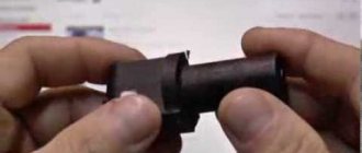
Configuration and device
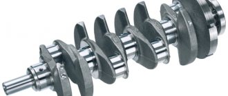
The product corresponds to the name because it consists of several elbows. The knees are located on the same axis and are made in the form of protrusions of a complex configuration. They are equipped with connecting rods, to which pistons with rings are attached using pins. The crankshaft is cast together with the journals located between the cranks. The crankshaft rests on the journals and is secured in the cylinder block housing.
A shaft that was loosely secured would not be able to rotate for such a long period. Therefore, its mounting journals are located along the entire length, creating a number of support points in the cylinder block on special bearings. Their name is root bearings. Instead of rollers and balls, they use abundant lubricant. During operation, it flows in a continuous stream between the main liners and support journals through special channels.
During the operation of a car engine, the crankshaft gets used to it. No experienced mechanic will move a used crankshaft to another block. At the front, on the toe of the crankshaft, a keyway is cut out with a milling machine. During the operation of the mechanism, the following are attached to the keys: a timing drive sprocket, a pulley for driving auxiliary mechanisms.
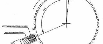
MAGNETIC CRANKSHAFT POSITION SENSORS
A magnetic resistance sensor is basically a single wire wrapped around a permanent magnet, with each end of the wire representing a positive or negative pole. When the rotating tooth of the iron reactor passes the sensor, it generates an alternating current (AC) signal to the ECU.
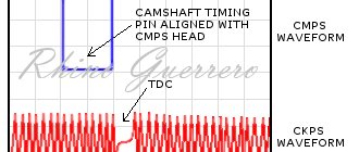
Oscillogram of the crankshaft sensor
In Photo 4 , notice that the "analog" signal varies between approximately 0.8 positive volts and 0.2 negative volts. Because AC voltage can be displayed more accurately in a laboratory setting than a voltmeter, it is easier to monitor the voltage as it alternates between positive and negative. In this case, the ECU “reads” the DPKV when the sensor signal crosses the zero voltage line. The accuracy of the resistance sensor varies slightly due to the voltage switching from positive to negative at slightly different points along the "zero" line. The accuracy of the resistance sensor can also be affected by the sensor magnet attracting ferrous metal particles from clutch linings or wear parts.
In most applications, the rotor of the number one cylinder is slightly modified to provide a "signature" waveform indicating to the ECU when that cylinder reaches DPCV. When diagnosing a reluctance sensor, it is very important to remember that the output voltage or amplitude is largely dependent on the air gap between the sensor tip and the reactor and the rotation speed of the reactor.
Detection of crankshaft defects
Malfunctions of the crankshaft of a car engine lead to the destruction of the entire cylinder block. Therefore, during operation, daily thorough inspection of these units is necessary.
Sometimes after assembly, dents, scuffs, and chips of metal remain on the sliding plane of the connecting rod and main journals. It happens that insufficient lubricant pressure is created in the system, or the oil is of poor quality.
Engine crankshaft failures occur due to overheating, oil dilution, and excessive clogging of the oil filter. A common failure is oil seal leakage, which occurs due to scratches or cracks on the part. These defects can appear in the metal due to the long life of the vehicle. Another possible reason is the lack of a mesh on the oil filler neck.
During the next oil change, unscrupulous mechanics can fill it with a dirty product containing stones, metal shavings, and pieces of metal. Due to the lack of a mesh, foreign bodies enter the oil system, causing irreparable harm. It is necessary to monitor engine oil seals for oil leaks. Don't panic if the seals leak.
Replacement of the crankshaft is carried out in extreme cases. It can be restored, fused, re-bored, and polished more than once. Even with heavy wear, the engine crankshaft will still serve for many years. Repair shafts are no different from new units. They are equipped with new piston groups, oil seals, liners, rings, and the engine will continue to operate.
Symptoms of a problem
How to check the crankshaft sensor?
This issue is relevant for many car enthusiasts and requires attention to study. It is impossible to imagine a modern car without a crankshaft position sensor. It is he who tells the computer where the crankshaft is now and which cylinder is currently running. There are a lot of malfunctions with which the DPKV on a VAZ 2114 car may be connected in one way or another:
- instability of speed;
- no readings on the dashboard when trying to start the engine;
- deterioration of vehicle dynamics;
- speed mismatch.
Taking into account all the above-mentioned malfunctions, we can conclude that the VAZ 2114 DPKV is an integral part in the operation of the engine. Thanks to its stable operation, driving becomes smooth, soft and controlled. But this is exactly what every car enthusiast wants, to have a reliable four-wheeled horse that is completely under control and in good working order. So that when you lightly press the gas pedal, it quickly executes all commands and picks up the required speed.
The on-board computer of the VAZ 2114 car displays only one accident associated with DPKV - an error in the crankshaft position sensor “CHENG ENGINE”
Today there are several types of crankshaft position sensors. But they both have almost the same device. There is a steel core on which the winding is wound. When a metal object is brought up and removed from the sensitive surface, an EMF is induced in the windings. But at the same time, a small constant voltage is applied to it, that is, a kind of permanent electromagnet is obtained. When the field is distorted, the EMF is distorted, which is recorded by the on-board computer.
Based on the operating principle and design of the crankshaft position sensor, we can list the following methods for checking it:
- checking the crankshaft position sensor by measuring resistance with a multimeter or pointer tester;
- measure the output voltage with the device when the engine is running in AC voltage measurement mode;
- using an oscilloscope.
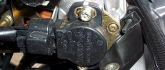
Before you start checking the sensor, you should first make sure that the gap is correct and that there is no dirt on it. Especially metal dust and graphite lubricants. All this can replace a metal object, which will become a source of interference. The gap should be no more than 1 mm and the sensor should be clean.
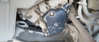
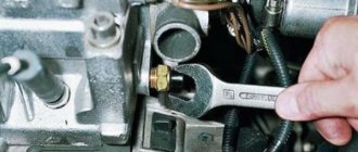
After visual inspection of its condition and position in place, it is necessary to remove it. This is made even easier because it is secured with just one bolt in a special bracket, which in turn is part of the side cover of the engine of a VAZ 2114 car. Having removed the sensor from the mount, carefully inspect it for external defects, which could lead to its failure building. After you are convinced of its external integrity, you need to begin diagnosing using additional devices.
Repair dimensions
Each repair size of the engine crankshaft has its own numerical values. Checking the car crankshaft:
- install the shaft so that the outer main journals rest on two prisms, check with a runout indicator;
- the runout of the landing plane under the main gear of the oil pump and main journals should be no more than 0.03 mm;
- the runout of the landing plane under the flywheel should be no more than 0.04 mm;
- the runout of the planes under the pulleys at the points of contact with the valve seals should be no more than 0.04 mm.
The connecting rod journals must be ground if there are scratches or wear of more than 0.03 mm. The ovality of the necks should not exceed 0.03 mm.
CRANKSHAFT POSITION SENSOR (CPSE)
In short, the crankshaft position sensor (CPS) detects when each piston reaches top dead center (TDC). To calculate the timing of the spark, the ECU calculates the angular position of the crankshaft connecting rod relative to TDC. To illustrate this, the ECU can time the spark to occur 10° before top dead center (TDC) on the compression stroke. See Photo 1.
Photo 1
CKP also detects cylinder misfires in post-1996 OBD II engines by measuring very small variations in crankshaft speed. For example, the crankshaft slows down as the cylinder approaches TDC on the compression stroke. After combustion, the crankshaft accelerates on the drive stroke to approximately 90° after top dead center, when cylinder pressure is used up and the connecting rod angle is reduced. When this very predictable deceleration and acceleration pattern is continually disrupted, the ECU stores a misfire trouble code for that cylinder.
Table 2.1. — Technical requirements for eliminating defects in the ZIL-130 crankshaft
| Replacing crankshaft oil seals where to start Drawing Position | Name of defect | Defect identification tool | Dimensions, mm | Conclusion | |
| nominal | acceptable | ||||
| 1 | Shaft bending | Prisms, indicator | 0,02 | 0,05 | Editing using the PPD method |
| 2 | Wear of connecting rod journals along the length | Template 58.32 | 58+0,012 | 58,32 | Reject if the length is more than 58.32 |
| 3 | Wear of connecting rod journals of a more recent repair size | Micrometer 50-75 mm | 65,5-0,013 | ___ | Restoration to nominal size |
| 4 | Wear of main journals of a more recent repair size | Micrometer 50-75 mm | 75-0,013 | ___ | Same |
| 5 | Wear of the journal under the gear and crankshaft pulley | Micrometer 25-50 mm | 46-0,050 | 45,92 | Same |
| 6 | Runout of the end surface of the shaft flange | Micrometer 0-25 mm | 0,10 | 0,10 | Grind “as cleanly” to size 9.5 mm |
| 7 | Worn bearing hole | Indicator nutrometer 50-100 mm | 52-0,040 | 52,01 | Restoration to nominal size |
Features and purpose of machines.
A feature of most modern machines is the ability to process the connecting rod journal without re-installing the chuck. It is possible to choose a machine configuration with a table equipped with hydraulics. The feed of this table is divided into transverse and smoothly variable.
A typical crankshaft grinding machine has the following features:
- All machines are equipped with a system that allows you to check the position of the crankshaft. The placement of cartridges is mutual and is carried out in four directions. A reliable clamp will allow you to quickly center the shaft. The cartridges are equipped with indicators that monitor the position.
- If you move the head against the main stopper, which serves as the basis for the correction, position O is established.
- The cartridges rotate 360 degrees.
- Rotation is available with micrometric precision.
- Easy replacement of central chucks.
- The mounts are equipped with only two types of clamps, making it easy to maintain using only 2 types of wrenches.
- Crankpins and main journals can be machined at centers.
Particular attention should be paid to the material from which the main parts are made. It must be durable, since it bears the main load
The purpose of the above parts is to continuously fix the part with subsequent manipulations during processing.