Cars admin26.02.2020
The main signs of a malfunction of the mass air flow sensor are loss of engine power, difficult starting, “floating” engine speed. To find out the exact cause of the flow meter failure, you need to visually inspect the device and then test it with a scanner (via Openidag), a voltmeter or a motor tester.
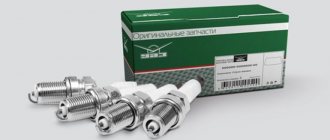
Replacing the air flow sensor
If after cleaning it is not possible to restore the VU meter’s functionality, the engine runs unstably and has lost acceleration dynamics, the sensor should be replaced. The manual for each vehicle describes in detail the replacement of a standard, exhausted air flow sensor with an identical sensor.
It is much more difficult for owners whose cars had discontinued filament sensors. Or the user decided to save money by choosing a cheaper film mass air flow sensor. When installing substitutes, you should consider the following nuances:
- together with the mass air flow sensor, you need to use a new wiring bundle;
- in the standard version of the firmware, the chick axles are removed from the items “Potentiometer CO” and “Max air flow sensor with burning”;
- reconnection consists of connecting contacts 1 and 4 on the sensor connector.
Rice. 15 Re-soldering the MIKAS controller for a new mass air flow sensor
Thus, diagnosing the mass air flow sensor is possible on your own without visiting a service station. But when switching to a VU meter of a different design, you should contact specialists, since it will require resoldering the controller or reflashing the ECU.
Diagnostics of mass air flow sensor
In principle, the mass air flow sensor is not as critical for starting the engine as, for example, the DPKV. It can be turned off by pulling out the connector, the ECU will go into emergency mode and will determine portions of air in the fuel mixture using another sensor - the TPS throttle position.
Therefore, the breakdown is determined in several stages according to the degree of complexity:
- visual inspection and disconnection of the sensor;
- determining the compliance of a specific modification of the mass flow sensor with the ECU firmware;
- diagnostics with a tester in voltmeter mode.
This will reduce the complexity of the process. For example, before checking the mass air flow sensor with a tester, you should make sure that the sensor is compatible with a specific MIKAS controller and that the original brains have not been flashed.
Visual inspection
The mass air flow sensor is checked after access to this sensor is provided. To do this, you will need to partially dismantle the air intake elements (usually the corrugation). Knowing how a VU meter works, you can visually detect mechanical damage or traces of liquids/dirt in the pipe.
Rice. 11 Inspection of the air sensor and corrugation
Oil gets inside the corrugation due to a clogged oil sump of the crankcase ventilation system or when the lubricant level inside it increases. If the machine's maintenance schedule is violated, dust and dirt get onto the walls of the pipe, as the air filter becomes clogged.
After removing the sensor from the air filter housing, the inlet mesh should be clean. If there is a build-up of dust, most likely the rubber seal was not installed tightly and unfiltered air was getting inside. In any of these cases, the operation of the mass air flow sensor is disrupted by default.
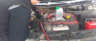
Diagnostics on the move
The following method for checking the air sensor allows you to determine its performance. You don’t need a tester or other tools for this:
- Diagnostics of the mass air flow sensor is carried out after disconnecting the ECU connector;
- the engine starts, Check lights up on the panel, indicating a sensor malfunction;
- however, the controller goes into emergency mode, ensuring the operation of the internal combustion engine;
- If the dynamic characteristics of the engine improve when driving with the air sensor turned off, then the mass air flow sensor is faulty.
Rice. 12 Disabling the mass air flow sensor
Compliance of the mass flow sensor with the ECU firmware
As necessary, owners reflash the computer's brains to improve performance, while getting side problems. For example, if the MIKAS controller has been updated with firmware, the mass air flow sensor may not work correctly.
In this case, it is fundamentally incorrect to talk about a sensor malfunction, but its signals are not intended for the new version of the MIKAS controller that was installed on it. In this case, the only way to identify signs of a malfunction in the mass air flow sensor is:
- change the angle of the throttle valve (usually a 1 mm shim near the throttle stop);
- disconnect the mass air flow sensor while the engine is running (pull the chip out of the connector).
Checking with a multimeter
If it was not possible to diagnose sensor malfunctions at the previous stages, and it is compatible with the version of the ECU controller used, the tester checks using the following technology:
- the multimeter switches to 2 V mode (voltmeter);
- a beam pinout diagram is placed in front of your eyes;
- The ignition is turned on, the black probe of the ground tester, the red to the yellow wire.
Rice. 13 Scheme for checking the mass air flow sensor with a tester
Then, with the engines turned off, the readings are taken with a multimeter, taking into account the following factors:
- the new device will show 0.99 - 1.01 V;
- within 1.02 V is considered a good sensor condition;
- 1.03 – 1.04 V indicates the end of the device’s service life;
- more than 1.5 V indicates the need for replacement.
The table below contains the beam pinout parameters:
| The wire | Entrance | Exit |
| green | – | weight |
| yellow | signal to sensor | – |
| darkest | – | to main relay |
| lightest (striped) | supply voltage | – |
These symptoms can be diagnosed by the on-board computer in the UAMV parameter group.
How to trick a broken mass air flow sensor using a resistor
Let's consider the “restoration” option using the example of a VAZ 2110. After an unreasonable increase in fuel consumption, you decide to check the mass flow sensor with a multimeter. The readings at rest significantly exceed the ideal “no higher than 1.02 V” and even the acceptable “1.05 V”.
Accordingly, the engine sees a lean fuel-air mixture and adds more gasoline to the ratio. The result is an increase in consumption without an increase in power.
How to reduce the voltage at the ADC output of a flow meter? We know that based on the calibration of the mass air flow sensor in the electronic engine control unit, each value in volts corresponds to the volume of air in kg/hour.
How to reduce tension? Any novice electrician will tell you that you need to add resistance (additional resistor). Of course, it will not be possible to guess (or even calculate) the required value, so it is better to use a variable resistor in the range from 1 kOhm to 2 kOhm. Old Soviet SP-1 alternators are suitable. They will not fall apart from moisture or temperature under the hood.
The resistor is connected to the break in the wire running from contact No. 5 of the VAZ mass air flow sensor to the engine ECU controller.
Important: All work on the wiring harness is performed with the battery disconnected.
After connecting, we check the flow meter at rest:
- connect the multimeter to contacts No. 3 (ground) and No. 5 (ADC signal) of the mass air flow sensor connector;
- turn on the ignition without starting the engine;
- By tightening the variable resistor regulator, we achieve a value of 1 volt.
After this, it is necessary to mechanically secure the resistor so that it does not break during movement. We carry out a test drive and make sure that gasoline consumption is reduced.
Cleaning the air flow meter
Since the manufacturers do not provide for repair of the mass air flow sensor, this electrical device is considered “consumable”. There is no consensus on the possibility of cleaning to restore performance, even among service station professionals. If the car owner nevertheless decides to clean the mass air flow sensor on his own, it is necessary to take into account the nuances of the technology:
- the cleaner should not contain acetone or ether;
- Cotton swabs and compressed air are prohibited;
- most often WD-40 or Air Senso Clean from CRC is used;
- After removing the device, the spray is applied to it evenly with a powerful jet, the dirt dissolves and flows off under its own weight.
Rice. 14 Cleaning the VU meter with spray
Installation of the mass air flow sensor in place is possible after drying the surfaces without using a hair dryer.
How to clean the mass air flow sensor
https://youtube.com/watch?v=L-_O3dXU6sM
It is not possible to repair the mass air flow sensor with your own hands, since the threads inside the sensor cannot be replaced. Therefore, you can only replace it with a new one or try to clean it. The air flow sensor is quite expensive, so it is advisable to try washing the threads. In half of the cases, this helps and after using the mass air flow sensor cleaner, the engine starts working normally. Under no circumstances should you use aggressive solutions to clean the sensor. If you apply acetone or carbocleaner, the threads will most likely be damaged and the sensor cannot be restored. It is advisable to use Liqui Moly air flow sensor cleaner. Also a fairly high-quality product is the Luftmassensensor Reiniger air flow sensor cleaner. Among folk remedies, formic alcohol is often used. To clean, the sensor must be carefully removed without touching the threads. Then a cleaner is applied to the threads inside. The liquid is applied several times at intervals of half an hour so that all deposits can dissolve. After washing, the sensor dries and is installed in the car. Do not use a hair dryer or other devices for drying. DMRV is one of the most important sensors in a car, as it is responsible for the formation of the fuel mixture and normal engine operation. If it breaks down, engine performance deteriorates and consumption increases greatly. Therefore, it is advisable not to delay repairs and replace or clean the sensor as quickly as possible.
Checking and repairing at home
There are eight ways to independently check amplitude and frequency mass flow sensors.
Method No. 1 - disabling the air flow meter
The method consists of disconnecting the sensor from the fuel system of the car and checking the functionality of the system without it. To do this, you need to disconnect the device from the connector and start the engine. Without a mass air flow sensor, the controller receives a signal to switch to emergency operation mode. It prepares the air-fuel mixture only based on the throttle position. If the car moves faster and does not stall, it means that the device is faulty and requires repair or replacement.
Method No. 2 - flashing the electronic control unit
If the standard firmware has been changed, then it is unknown what reaction of the controller is programmed in it in case of an emergency. In this case, you should try to insert a 1mm thick plate under the throttle stop. The turnover should increase. Now you need to pull out the chip from the air flow meter. If the power unit continues to work, then the cause of the malfunction is the firmware.
Basic faults
There is practically nothing to break in a film sensor, so they are considered “eternal”. The spiral of filament air flow sensors is less reliable, however, these electronic devices cannot be repaired in principle, with the exception of cleaning and replacement. The following symptoms will help determine the malfunction of this particular sensor:
- spontaneous decrease in engine power;
- decreased acceleration dynamics;
- engine not ;
- increase in fuel consumption unjustified by driving style;
- illuminated Check errors;
- change in XX speed in any direction, appearance of jerks;
- The car stalls when changing gears.
When diagnosing a low signal level, the following options are possible:
- the plug fell off;
- the power supply is broken;
- oxidation or loss of mass;
- signal wire break.
Rice. 10 Mechanical damage to the VU meter
Since the electrical device is not repairable, but has a simple design, diagnostics can be performed on your own according to the principle of increasing its complexity.
Replacement
It is not difficult to replace the mass air flow sensor with your own hands, even if you do not have any special skills in car repair. Having checked the condition of the device and determined that cleaning will not help, all that remains is to replace it.
- Place the car on a level surface, lift the hood and remove the negative terminal from the battery.
- Disconnect the sensor connector. We have already talked about its location, so there will be no problems with the search.
- Using a screwdriver, remove the clamping bolt of the clamp that secures the corrugation to the mass air flow sensor.
- The corrugation is removed.
- Using a 10mm wrench, unscrew the two bolts that hold the sensor to the air filter housing.
- After removing the failed oxygen sensor, install a new regulator in its place.
- Screw back a couple of bolts, secure the corrugation and secure it with a clamp.
- Reconnect the connector and return the negative terminal to the battery.
If everything is done correctly and the breakdown is correctly identified, then the engine will return to its previous performance and the error signal on the dashboard will disappear.
Replacing the device
To finally check the result of the repair, go out onto the road, do a test drive and be sure to try to press the gas pedal sharply. If the dynamics and power become the same as before the problems arose, you did everything correctly, and it was the mass air flow sensor that was the culprit of the malfunction.
How to deceive the mass air flow sensor using ECU firmware
The good thing about the previous method is that its implementation does not require complex equipment or painstaking work. If you were able to check the voltage at the output of the flow meter with a multimeter (which means you at least have one), and know how to hold a soldering iron in your hands, installing a resistor in the wire gap will not be difficult. However, the dependence of voltage on air flow mass is nonlinear. And when the throttle valve opens, the error of the signal corrected by the resistor at rest will increase. Accordingly, the fuel-air mixture will not be ideal.
This means that you need to adjust the MAF calibration in the ECU firmware.
Attention! If you do not have experience working with car software, it is better to entrust this operation to professionals.
- We install the specialized tuning program “DFID Corrector” on the laptop.
- We connect the car scanner to the OBD-II connector and establish communication between the ECU and the computer.
Important! During operations with the ECU controller firmware, the 12 volt power supply should not be lost. Therefore, you need to make sure that the battery is fully charged.
- We adjust the voltage of the MAF ADC at rest (air mass 0 kg/hour) to the required 1 V.
- Save the firmware changes.
After calibration, the data on mass air flow will be correct throughout the entire engine speed range.
Attention: After you install a new flow meter, you must return the calibration to the factory (standard) state.
Design of the mass air flow sensor
Car enthusiasts call the mass air flow sensor a flow meter; in specialized literature it is designated as a volume meter. What is actually measured inside this electronic device is not the volume of air passing through it, but its mass per unit of time, moreover, compressed.
Since Ohm's law is familiar to every school graduate, the design of the mass air flow sensor is understandable to 100% of car enthusiasts:
- the device is analogous to an anemometer that measures flow speed;
- inside a tubular housing with an air deflector and a mesh metal screen at the inlet, the sensor itself is inserted perpendicular to the flow with a connector extending outward;
- Apply a current of 500 - 1200 µA to the thread or film inside the sensor, remove the voltage value 0 - 1 V in reverse flow or 1 - 5 V in normal mode;
- when current passes, the element heats up, its resistance increases (500 - 700 Ohms), and the voltage changes accordingly;
- The air flow cools the wire, the resistance decreases, and the voltage increases.
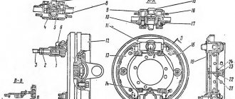
Rice. 4 Design of filament air flow sensor
The mass air flow sensor is connected according to the diagram below:
- green – to ground;
- white-gray – output voltage;
- yellow – input signal;
- dark – output signal.
Rice. 5 DMRV connection diagram
The film MAF has a built-in platinum resistor on a ceramic plate. In a filament sensor, the resistance is made of an alloy of iridium and platinum. The first VAZ models were equipped with sensors that controlled the flow rate based on the frequency of the output signal. Currently, domestic and foreign cars have mass flow sensors that determine fuel consumption based on voltage.
Rice. 6 Film mass air flow sensor
To increase functionality, the operating sensor uses two temperature-dependent elements. Since the difference in air temperature can introduce an error into the device readings, the second thread element compensates for it by measuring the temperature of the environment. Common to all devices is the presence of an adjusting screw, which is used to adjust the CO with your own hands. The designs of different manufacturers differ in the following details:
- thread thickness – 0.07 – 1 mm;
- method of fastening the thermally dependent element - laser welding, hooking with a loop on an elastic suspension;
- thread geometry – V-shaped or U-shaped;
- The design of the stand is square, eliminating errors when rotating the element around its axis.
Rice. 7 German sensor and Russian analogue
In addition to these differences, factors to consider:
- thread devices began to be produced by Bosch and General Motors, then interchangeable analogues appeared from the APZ and JSCB Impuls plants;
- introduced a film-based air flow sensor from Siemens, which was copied by the Kaluga Research and Production Enterprise AVTEL;
- the thread is heated to 140 - 170 degrees, the film to 100 degrees;
- the accuracy of measuring film modifications is lower - 4%, for thread modifications is higher - 1%;
- The devices are interchangeable with each other, but only together with a bundle of wires, since the pinout of the wires does not match.
Rice. 8 Sensor connector
Currently, thread sensors are discontinued in Europe for a number of reasons:
- low level of manufacturability of thread production;
- the presence of corrective lambda probes;
- automatic calibration of films in blowing units.
In other words, manufacturers sacrificed speed and high accuracy for the sake of significantly reducing the cost of film mass air flow sensors.
There is a domestically produced mass air flow sensor M with protection against overvoltage, short circuit and conducted interference.
Rice. 9 Modification of mass air flow sensor M
By default, thread sensors are based on the principle of self-cleaning of a temperature-dependent element. After stopping the engine, the ECU independently supplies current to the filament to warm it up to 1000 degrees for 1 second. The adhering dirt burns out completely.
Signs of a malfunctioning mass air flow sensor (MAF). How to check DMRV
In cases where the mass air flow sensor on a car fails, signs of a malfunction may appear in the form of the characteristic symptoms described below.
- “check engine” indication on the instrument panel;
- difficult engine starting;
- inability to start the engine when cranked by the starter;
- Unstable engine operation at idle speed;
- drops in speed when pressing the accelerator pedal;
- loss of power, difficulty gaining speed;
- increased fuel consumption.
Author: Raul_ HF and wheel alignment mechanic; experience - 3 years.
Service/repair consultant at Toyota DC; experience - 4 years.
Purpose of the mass air flow sensor
The mass air flow meter, or MAF sensor, also known as an air flow meter, is one of the components of the fuel-air system and measures the volume of air that enters directly into the combustion chambers of the engine. The amount of air taken in depends on the throttle position.
Based on the sensor data, the internal combustion engine electronic control unit calculates the required volume of fuel that needs to be injected into the cylinder chambers. Correct operation of the mass air flow sensor guarantees the optimal ratio of the components of the combustible mixture for its complete combustion during the engine cycle. In turn, the power unit produces the best ratio of power and fuel consumption.
The mass air flow sensor is present on all models of gasoline engines that are equipped with electronic fuel injection. Structurally located between the air filter and the throttle valve.
Reasons for failure of the mass flow sensor
The MAF sensor (mass air flow meter) measures the volume of air through the effect of air flow on a sensing element, which in some cases is a film, and in others a thread, which are made of platinum. A certain voltage is applied to the working element, as a result of which it heats up. The air flow cools the element. By measuring the rate of temperature drop, the computer calculates how much air has passed through the sensor per calculated unit of time. Based on the data obtained, a signal is sent to the injection system about the required amount of fuel to create a high-quality combustible mixture.
The weak point of the unit is the heating element. Over time, tiny dust particles settle on it, forming a coating that disrupts normal cooling. Calculations of the volume of air passing through the sensor do not correspond to real values, which causes failures in the injection system. The computer pours fuel based on false signals, which affects the overall efficiency of the engine.
In some cases, characteristic signs of a malfunction of the mass air flow sensor may appear not as a result of a breakdown of the sensor itself, but as a result of air leakage bypassing it. For example, if the air duct seal is broken. Thus, the correct functioning of the air supply system becomes impossible. Typically, mechanical damage is easily detected by dismantling and carefully inspecting the pipe. Especially often its integrity is violated in the area of connecting elements and at bends. In this case, the problem is solved by replacing or restoring the damaged part.
How to check the performance of the mass air flow sensor
If characteristic signs of malfunction and failure of the air flow meter (MAF) appear in the engine operation, there are simple methods to check its performance and determine the cause of the malfunction on your own. To do this, it is enough to understand the principles of operation of this sensor as a component of the system.
The electronic engine control unit regulates the fuel supply based on signals from the MAF sensor, and if it fails, it switches the system to emergency mode. Gasoline supply begins to be calculated based on the readings of the throttle position sensor and crankshaft sensor, however, the fuel injection parameters based on these data are very approximate. On some cars in this mode of engine operation, idle speed increases to 1500-2000 thousand.
To perform self-diagnosis, it is enough to disconnect the MAF sensor chip with the engine running. If this is accompanied by an increase in the speed of the power unit, the sensor is working. But on some car models this may not happen, so you need to do a test drive and pay attention to the car’s behavior. If the acceleration dynamics have noticeably improved, then the problem is really in the mass air flow sensor.
Additionally, it is worth carrying out control measurements with a high-precision multimeter, if available. The check is carried out with the engine not running and the ignition on. The voltage readings at the output of a working sensor should be within the limits of 0.9 to 1.4 Volts; exceeding this threshold usually indicates a malfunction of the unit.
DMRV service life
The service life of the mass air flow sensor directly depends on the purity of the air passing through it. The probable cause of flow meter failure as a result of contamination of the heating elements of the flow meter can be identified by removing the sensor and visually inspecting their condition. Deposits on working surfaces will indicate the need to replace the unit or attempt to clean the deposit.
You can extend the service life of the mass air flow sensor by independently monitoring the condition of the engine air filter element and promptly replacing it with a new one. For very dusty Russian roads, which is observed in most regions, the filter may need to be replaced several times in one year or every five to six thousand kilometers. At the same time, the official maintenance regulations for most cars specify a replacement interval no more often than a visit to the next maintenance. Depending on the production, the vehicle service interval can be 10,000 km or 15,000 km.
An air filter clogged with dust will inevitably accelerate the formation of destructive deposits on the sensitive elements of the air flow sensor and reduce its service life. Due to the obstructed passage of air and its insufficiency for normal engine operation, the combustible mixture will be enriched, and a side effect will be increased fuel consumption.
Methods for troubleshooting DMRV
In some cases, cleaning the mass air flow sensor is allowed, but this depends on the design features of the working sensitive elements of the unit. But even with a favorable outcome, this is a temporary measure and the restored sensor will not be enough for a long time. If a node fails, it is usually replaced entirely with a new one.
When purchasing a mass air flow sensor, you must take into account that the new sensor must exactly match the standard one. This must be an original part with the same catalog number. In other cases, normal operation of the internal combustion engine is not guaranteed, even if the external sensors are absolutely identical. The original flow meter is not cheap due to the complexity of its production and the need to use expensive components.
Problems with the power unit can be caused by malfunctions in a number of systems: ignition, fuel or air supply, camshaft position sensors, crankshaft and a number of others. However, one of the likely reasons for the appearance of the above signs of car malfunctions is the failure of the MAF sensor. You can try to avoid the costs of complex engine diagnostics at a car service center. To do this, it is enough to know how to check the mass air flow sensor (MAF) yourself, by applying the simple methods proposed above.
autoabra.com