How to deal with engine vibration
The power and speed of cars are growing in proportion to the public's needs for comfort. And increasing engine power is associated with a lot of problems that do not always coexist peacefully with comfort and other requirements for modern technology. This includes increased fuel consumption, uneven engine operation, increased noise and vibration. If for a sports car all these conventions can be written off, then a comfortable business-class car must fully meet the requirements for comfort.
Vibrations have always bothered designers and there is no escape from vibrations. It is possible to calm a vibrating part or shaft only by creating an anti-load, a counterweight. And this, naturally, increases the mass of the mechanism. For example, you can look at wheel balancing at a tire shop. If you do not hang a load of a certain weight on the wheel in a certain place, vibration cannot be avoided. But we will increase the sprung mass, which is harmful to the condition of the chassis. Almost the same story is observed with the crankshaft of a car. To avoid unnecessary vibrations, a special balancer or flywheel is used.
Physics[ | ]
The kinetic energy of rotation accumulated in a rotating body (flywheel) can be calculated by the formula:
Flywheel of a factory stationary steam engine E = 1 2 I ω 2 {\displaystyle E={\frac {1}{2}}I\omega ^{2}}
Where:
- I {\displaystyle I} - moment of inertia of the mass relative to the axis of rotation of the flywheel
- ω {\displaystyle \omega } (omega)
- angular velocity in radians per second
For simple flywheel shapes, finite expressions for the moment of inertia are known
- For a hollow cylinder I = 1 2 m ( r 2 + ro 2 ) {\displaystyle I={\frac {1}{2}}m(r^{2}+r_{o}^{2})} where m {\displaystyle m} is the mass of the hollow cylinder; r {\displaystyle r} is its radius; ro {\displaystyle r_{o}} — internal radius of the cylinder
- For a thin-walled cylinder I = mr 2 {\displaystyle I=mr^{2}}
- For a solid cylinder I = 1 2 mr 2 {\displaystyle I={\frac {1}{2}}mr^{2}}
By replacing the angular velocity ω {\displaystyle \omega } in the formula for a hollow cylinder with the rotation frequency f {\displaystyle f} according to the formula
ω = 2 π f {\displaystyle \omega =2\pi f}
we get
E = m ( π f ) 2 ( r 2 + ro 2 ) {\displaystyle E=m(\pi f)^{2}(r^{2}+r_{o}^{2})}
What is a dual mass flywheel
In the mid-80s, the use of springs to dampen torsional vibrations in the clutch basket completely exhausted itself. The spring could no longer guarantee the complete absence of vibrations due to the fact that the mass of the pistons, connecting rods, and all rotating and moving engine parts in the total volume exceeded the damping capabilities of the springs. The increase in torque at the crankshaft output flange also required more effective vibration control.
Vibrations in themselves are not very pleasant, but in addition, they destroy the bearings, shafts and gears of the gearbox, loosen the fastenings, and reduce the life of components and assemblies. Therefore, they designed a dual-mass flywheel, which, using a torsion-spring lever system, was able to absorb vibrations almost entirely. In general, the use of dual-mass flywheels gave the transmission and the car as a whole a number of advantages:
- more comfortable gear shifting;
- reduction of moment of inertia during switching;
- increasing the service life of the gearbox and clutch;
- significant savings in space in the clutch housing, which is important for a modern car, where every millimeter is worth its weight in gold.
Usage
Used in machines that have an uneven supply or use of energy, storing energy when the energy supply is higher than the consumption, and releasing it when the consumption exceeds the energy supply. Also used in a hybrid engine as energy storage and for regenerative braking.
Often the function of a flywheel is performed by a massive rotating element of the mechanism. Such as a potter's wheel, massive watermill wheels or massive gear wheels.
In addition to energy, a rotating flywheel (like any rotating body) also has angular momentum, which is associated with the observation of the gyroscopic effect, which consists in the precession of the rotation axis around its original direction when an external force appears that does not coincide with the direction of the rotation axis.
The first example of the use of the gyroscopic effect can be considered the invention of the spinning top (yo-yo).
One of the first applications of the gyroscopic effect was the transition from firing round cannonballs to oblong projectiles, the rotation of which made it possible to maintain their orientation in space, and the oblong shape significantly increased their mass (blank) or explosive charge.
The flywheel is also the rotor of the gyroscope, used in gyrocompasses and in general in gyroscopic devices for orientation in space, in particular torpedoes (Aubrey device), rockets and spacecraft. The most common examples of a flywheel are a bicycle wheel or the rotating disk of an electric vinyl record player.
The ability of the flywheel to maintain the direction of the axis of rotation is used in ship stabilizers.
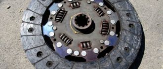
In everyday life, the flywheel is most often used in cars: any piston engine is equipped with a flywheel, often combining functions as part of the clutch and starting system (flywheels are equipped with a ring gear to transmit torque from the starter). In addition to bringing the crank mechanism out of its dead center, the flywheel in the engine reduces the unevenness of rotation to an acceptable level, which increases the service life of the transmission (the remaining unevenness is damped by the clutch disk springs or the automatic transmission clutch, then by torus rubber and viscous couplings).
How does a dual mass flywheel work?
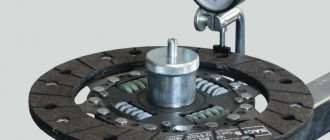
The unit is located between the motor and the clutch, and the principle of operation of the dual-mass flywheel is based not on increasing the mass of the counterweight, but on damping through a spring-torsion mechanism. Dual-mass flywheels come in several designs, but as a rule, they consist of two housings. On the first, main body, there is a starter gear, with the help of which the starter starts the engine. The 2nd body consists of standard clutch parts. The main trick and principle of operation lies in the ability to move these two elements relative to each other. They are connected by radial and thrust bearings, which ensure free rotation of the housings.
The damper-spring package, which is located between the two housings, works as a vibration damper, and in order for their operation to be clear and uniform, the internal space of the dual-mass flywheel is filled with grease. The design of the spring-damper package contains polymer separators; they prevent the springs from biting and jamming.
Operating principle
At the moment the internal combustion engine starts, rotation of the flywheel is ensured by the starter, the part receives an initial speed and gains inertia. Then the engine piston “hangs” at top dead center, and the shaft cannot rotate. However, due to the inertia of the flywheel, the crankshaft rotates slightly, which allows it to carry out the next compression cycle, ignite the fuel mixture, and obtain energy for the next rotation.
Rice. 12 The principle of operation of the flywheel with clutch
With a dual-mass flywheel the situation is slightly different:
- at the moment of start, one half of this assembly receives a high angular velocity, the second remains motionless;
- at the same time, the first half of the flywheel begins to compress the spring, which ensures smooth rotation of the transmission disk rigidly connected to it;
- then the speeds of both halves are aligned relative to each other and operate in a single mode;
- at the moment the driver slows down the gas pedal, the second half begins to overtake the first;
- however, a hard impact on the motor parts does not occur again, since another spring begins to compress in the opposite direction;
- the speeds of the halves are equalized again, the cycle repeats again.
Rice. 13 Operating principle of a dual-mass flywheel
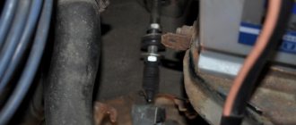
The DPKV sensor is still responsible for ignition, and the flywheel casing protects the unit from external influences. A similar damper is built into the clutch assembly, which becomes unnecessary when using a dual-mass flywheel.
Design and symptoms of a dual-mass flywheel malfunction
The spring-damper package operates on a two-stage principle. This means that the entire vibration load is absorbed in two stages and is absorbed virtually 100%. the first, softest stage, captures and dampens vibrations that occur during startup, at low speeds and when the engine is turned off. The second stage is more rigid and is designed to operate at high speeds; it resists torsional vibrations in normal mode.
Signs of a unit malfunction are obvious and are expressed in increased engine vibration at certain speeds. Before checking the dual-mass flywheel for malfunctions, it is necessary to completely dismantle the gearbox and place the flywheel on a special stand, where load curves will be measured, which will characterize the condition of the device. At ordinary service stations, such equipment is very rare, therefore, in general, flywheel restoration is not carried out. Either it is replaced with a conventional flywheel, taking into account the engine parameters, or a new one is selected. There are some strict limitations to consider before disassembling the flywheel. Firstly, any mechanical processing of flywheel parts is under no circumstances allowed. Secondly, all fasteners that were removed during dismantling must be replaced with new ones.
Only under such conditions will a restored dual-mass flywheel serve for a long time and reliably, and its service life is estimated at 350-400 thousand km with proper operation.
Super flywheel
Main article: Superflywheel
In May 1964, N.V. Gulia filed an application for the invention of a super flywheel - an energy-intensive and explosion-proof flywheel. Unlike a classic monolithic flywheel, a super flywheel is wound from thin tape, wire or synthetic fibers, which have significantly greater specific strength than a monolithic part (casting or forging), therefore the energy intensity of such a flywheel is much higher (according to the inventor, up to 1.8 MJ /kg). In addition, if the super flywheel ruptures, no large fragments are formed: the ends of the torn tape or fibers begin to brake against the casing, and the flywheel gradually stops.
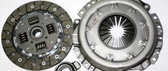
Clutch. Between engine and transmission
The car is constantly being improved. However, the goals, priorities and directions of its evolution change from time to time.Once upon a time, a “young” vehicle required reliability, comfort and ease of operation. Then security issues came first. After which, without rejecting what had already been achieved, they began to follow growing environmental requirements. Now to all this has been added the limitation of CO emissions (the level of standards for which they promise to only tighten).
It is important that every new step requires a radical revision
the previous design of a significant number of units, and to fulfill the last condition, each, without any exaggeration, component of the car has to be redesigned or redesigned at a completely different technical level.
Despite the abundance of companies involved in automotive components, there are, in general, few real experts, pioneers of new designs and technologies. But it is they who, through their joint efforts, make what we call the familiar phrase “modern car.” It is to them that honor, respect and glory, which very often do not come immediately, but all the “childhood illnesses” and “growing problems” throughout the program go to the pioneers.
Not everyone can lead the way; there are other ways of doing business. Some people find it more convenient to develop their own designs, based on principles already discovered and tested by someone else. Still others - and there are a lot of them - put
We are faced with the task of mass copying already known solutions, eliminating the shortage of spare parts in the global vehicle fleet. Everyone does their own thing, and any of these sinful paths has the right to exist with only one condition: someone must go first. Because without those who are looking for new ideas and designs, technologies and principles, this whole pyramid makes no sense. And, of course, only the former have complete information and see all the development trends of the units they specialize in. This means that to get an idea of these trends, you need to go to the experts.
Despite the abundance of companies engaged in automotive components, there are, in general, few real experts, pioneers of new designs and technologies.
Therefore, when the question arose about how the automobile clutch might change in the near future, the magazine turned to Schaeffler, which develops and produces the LuK brand clutch. The reader is offered a brief summary of the story of technical specialist Yuri Alexandrov.
The main modern trends in the development of the clutch unit, which is subject to particularly high loads in a car, according to LuK experts, can be briefly formulated as follows:
• development of the design of dual-mass flywheels and the emergence of dual-mass flywheels with a pendulum system;
• coordination of the service life of all clutch units and turning it into a single (non-separable for service stations) unit. At the end of its service life, such a clutch is replaced as an assembly;
• minimizing the size of the SAC and reducing the clutch release stroke;
• reducing the weight of the pressure plate due to changes in its production technology;
• development and supply to the secondary market of equipment and tools for diagnostics and guaranteed high-quality replacement of clutch units;
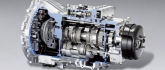
• further improvement of the dual-clutch transmission module of the DSG type.
Now let's talk about each of these areas in more detail.
From a dual-mass flywheel to a dual-mass flywheel with a pendulum system
The trend towards increasing engine power, with a gradual decrease in their displacement (and, as a consequence, a decrease in the number of cylinders), had already emerged by the 80s. last century. Small-volume engines fit well into the overall development strategy of the car, allowing it to meet many increasingly stringent requirements. However, their use threatens with a serious drawback - a significant increase in torsional vibrations, which in difficult cases even lead to the destruction of the transmission. To eliminate this phenomenon, back in 1980, BMW commissioned LuK to create a dual-mass flywheel. The task was completed brilliantly. Nowadays it is impossible to imagine any modern car without this unit. In addition to passenger cars, dual-mass flywheels are already installed on the entire European fleet of commercial vehicles; they are becoming widespread on buses, including tourist and intercity buses. There are prerequisites for the appearance of dual-mass flywheels in trucks.
This is a very successful, widely sought-after design that has become a sales locomotive and the company’s calling card for many years. The dual-mass flywheel is destined to have a long life under the hood of cars, because only more than 30 years after the development of this most important unit, some of its characteristics cease to satisfy manufacturers of the most modern engines. A number of consumers already want even greater efficiency in damping torsional vibrations at frequencies that are increasingly characteristic of modern engines. The desire (to meet environmental requirements and save fuel) to make the engine operating speed as low as possible forces engine builders to approach the zone of resonance phenomena. To eliminate these problems and effectively dampen low-frequency vibrations, LuK proposed a further design development of dual-mass flywheels - dual-mass flywheels with a pendulum system. In this design, 3 or 4 massive parts are added to the dual-mass flywheel, secured in such a way that they are free to oscillate around a central position. Moving in irotivophase, they help dampen low-frequency vibrations, reducing them to the values of client expectation.
Several options for placing the pendulum masses of the clutch assembly have been proposed:
• inside the flywheel they are movably riveted to a special flange;
• on the moving “mass” of the flywheel (this design does not require a flange);
• outside the dual-mass flywheel;
• on the clutch basket housing.
The “Big Three” German automakers not only became interested in this design, but have already begun producing cars, albeit the most expensive versions so far, equipped with a pendulum-type dual-mass flywheel.
Coordination of the service life of all clutch units and the requirement for a comprehensive replacement of the entire unit at the end of its service life
In accordance with the requirements of manufacturers and with the constant increase in engine power, the dual-mass flywheel has become noticeably more compact and lighter than the very first production designs, but its service life has also changed. Now, in accordance with the modern trend, a comprehensive replacement of the entire clutch assembly is increasingly being envisaged, the resources of all components of which (dual-mass flywheel, friction pressure plate, basket with diaphragm spring and hydraulic tire release bearing) are fully coordinated.
The clutch engagement system has also changed many times throughout its history. Following the mechanical, cable and hydromechanical drive, a hydraulic release bearing appeared, combining several components: a release bearing coupling, the bearing itself, usually with an automatic alignment system, a working cylinder and a guide sleeve. With this unit it has become much easier to control the clutch. Now they are going to take the next step in the development of the design - to integrate a hydraulic release bearing into the clutch basket housing, combining them into one unit.
It is believed that a comprehensive replacement is the most effective way to restore the operation of the entire clutch assembly. An example of such systems
The LuK design installed on one of the latest Volkswagen Golf cars can serve. The dual-mass flywheel and clutch basket are a single assembled unit, which is mounted to the crankshaft through special holes in the diaphragm spring.
Minimizing the automatic compensation system for wear of friction pairs of clutch parts and reducing the clutch release stroke
There seems to be some kind of paradox in reducing the size of clutch parts. Lotka says that in order to transmit more power, the size of the clutch must be increased, but the manufacturer demands the opposite, because this is the only way it can solve the broader problems facing it.
The problem is that when using a smaller diameter basket, the force of the diaphragm spring must be increased. But an increase in its stroke (as a result of operational wear of the friction pairs of the clutch parts) will lead to an unacceptable increase in the clutch release force. The driver simply will not be able to press the pedal.
To eliminate the increase in engagement force, LuK was the first in the world to create a system for automatic compensation of wear of friction pairs of clutch parts - SAC. In 1996, SAC was introduced on production commercial vehicles and then extended to all passenger cars. In addition to achieving driver comfort throughout the entire service life of the clutch, one of the distinctive advantages of the SAC system is an increase in clutch service life by one and a half times. This occurs thanks to a constant and optimal clamping force, which completely eliminates disc slippage.
It is for this reason that SAC first became widespread in commercial vehicles, where there are more stringent requirements for the life of clutch discs.
Now the development of the design of the automatic gap compensation system is moving towards achieving the smallest stroke when the clutch is disengaged and minimizing the dimensions of the entire assembly.
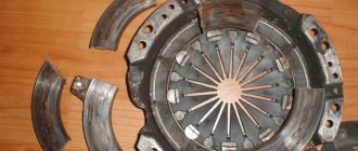
Lightweight pressure plate
The struggle to reduce weight leads to the appearance of a lightweight clutch pressure plate. LuK's replacement of the pressure plate production technology from casting to stamping from sheet material made it possible to obtain a pressure plate that is hollow inside, which is three times lighter than a stamped one.
Moreover, the thermal resistance of stamped pressure disks (this has already been proven) is higher than that of cast ones.
Device and tool for mounting and dismantling the clutch assembly
Schaeffler is practically the only company that offers the aftermarket all the necessary equipment for correct clutch replacement.
Firstly, the company’s assortment includes a set of special tools for checking and diagnosing the condition of dual-mass flywheels. The problem is that no one understands how to diagnose a dual mass flywheel. Even many dealers proceed from the instructions that say that if there is a suspicion that the dual-mass flywheel is not working properly, it should be replaced. The issue price can reach 2000 euros. However, the dual-mass flywheel is a fully digitally diagnosable unit, and the company can offer everything necessary for such diagnostics.
Secondly, the next most popular tool is the SAC installation tool. Now, on each package with a LuK clutch kit equipped with an automatic wear compensation mechanism, there is a red sticker indicating that if the clutch basket was installed without the use of special tools, then this kit of spare parts is not covered by any warranty.
Thirdly, we offer a tool for replacing the dual dry clutch module of Direct Shift Gearbox (DSG) transmissions. LuK is the only patent holder of such systems and in the aftermarket, offering all the necessary information and tools for these world's most efficient transmission systems. In terms of the engineering potential built into these units and the level of knowledge and required qualifications
LuK specialists are not of the opinion that the clutch is a conservative unit with an established design.
DSG gearboxes are the most demanding for maintenance. The company offers a special tool that completely eliminates the 9 risks that are included in the official tool. With the help of the tool offered by the company, you can do the work efficiently and take full responsibility for its results. We emphasize once again that the DSG gearbox is completely repairable. It can be restored for a reasonable price (with the necessary level of knowledge and special tools) to its ideal (original) condition.
Further improvement of the dual clutch module of the DSG gearbox
It is worth noting that the DSG gearbox has a module with two clutches (one for even gears, the other for odd gears), each of which is equipped with an automatic clearance adjustment system. This technology has a lot of interesting features. For example, clutches are in a nominally open state (clutches of other types of boxes are in a closed state). The DSG box makes it possible to consume 12% less fuel compared to a traditional type gearbox. The savings occur due to the fact that there is no torque gap when switching, and the control system allows you to always move in the most efficient mode, choosing the optimal one from seven short gears.
This greatest achievement of the company is now going through difficult times, but recently specialists have made serious design changes that eliminate a lot of childhood diseases of this design. In particular, the double clutch release unit was changed - release bearings with forks - and the software that controls the entire transmission was redesigned. These measures have made it possible to reduce the inherent defects of the first generation of DSG, which appeared back in 2007, to zero. The technology and design of the DSG will continue to be refined in the future. is not going to abandon DSG technology for a whole host of reasons. Among them, it is important that this transmission is recognized as ideal for future hybrids and electric vehicles. (In fact, Volkswagen has just unveiled the 10-speed KIII1 dual-clutch DSG in Vienna, as part of an overall strategy that aims to improve the performance of all vehicle systems that influence its movement by 15% by the end of the current decade.)
In conclusion, it is worth recalling that the strength of Schaeffler is that training on all types of transmissions is provided in Russia free of charge. Last year alone, 89 trainings were conducted, half of which were for the most promising auto centers across the country.
So, LuK experts are not of the opinion that the clutch is a conservative unit with an established design. It seems that the leader's tactics are that there is no component that he would not strive to improve, thus making his contribution to the creation of a modern car.
Alexander Shubin
History[ | ]
The flywheel effect has been used since ancient times. For example, in a potter's wheel, windmills. Probably one of the oldest examples of the use of a flywheel was an archaeological find from Mesopotamia (near the city) - a pottery machine with a disk of baked clay, about a meter in diameter and weighing at least a hundredweight. Similar inventions have repeatedly appeared in China.[1]
Flywheel from an old factory
According to the American medievalist Lynn White, the German monk Theophilus mentions in his treatise “On the Various Arts” several machines that use a flywheel[2].
During the Industrial Revolution, James Watt used a flywheel in a steam engine to smooth out motion and overcome piston dead ends[3], and his contemporary James Pickard used a flywheel in combination with a crank mechanism to convert reciprocating motion into rotational motion[4].
In the 20-30s of the 20th century, the Soviet inventor A. G. Ufimtsev was the first in the world [5] to use an inertial battery at the first wind power plant in Russia, which he built in Kursk.
The use of the flywheel as an energy accumulator is limited by the fact that when the permissible peripheral speed is exceeded, the flywheel ruptures, leading to great destruction. This forces the creation of flywheels with a very large margin of safety, which leads to a decrease in their efficiency.
The consequence of this is low (compared to other types of batteries) specific energy intensity.
Example[ | ]
The limiting value of the angular velocity of the flywheel ω {\displaystyle \omega } is determined by the tensile strength of the flywheel material. It is easy to show that for a flywheel in the form of a rotating disk 1 2 I ω 2 = V 4 S max {\displaystyle {\frac {1}{2}}I\omega ^{2}={\frac {V}{4} }S_{max}} , where S max {\displaystyle S_{max}} is the tensile strength of the flywheel material (tear force per unit area), V {\displaystyle V} is the volume of the disk. For fused quartz S max = 3 × 10 9 {\displaystyle S_{max}=3\times 10^{9}} N/m2. The energy intensity of a fused quartz flywheel with a volume of 0.1 m3 and a weight of 200 kg will be equal to the energy intensity of 13 liters of gasoline[6].