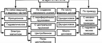
Transmission options
Today, cars use several types of transmissions: automatic, “robot”, “variator” and manual transmission (manual transmission, sometimes also called “manual”). The first has several types and is more technologically complex, but we will talk about it another time. Below we will talk about what mechanical transmissions and their automatic counterparts are.
By the way, one interesting fact needs to be mentioned here. Supercars and racing cars have a seven-speed gearbox. As experts say, it is this approach that allows you to get everything out of the car. They also say that what type of drive the car is equipped with will be of great importance: front or rear.
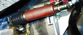
Clutch basket repair
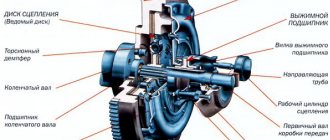
The clutch basket is the most complex component in the clutch.
It contains a pressure plate and a diaphragm spring, which are the main parts of a car's clutch.
If the clutch basket fails, the car may stop completely, or the clutch will slip, or it will be impossible to change gears.
Determining whether the clutch basket is faulty is difficult because it is impossible to diagnose it without removing the gearbox, which is an expensive and time-consuming procedure.
In the vast majority of cases, repairing the clutch basket is impossible, only replacing it with a new basket. Also, with the gearbox removed, you should inspect all components of the clutch and replace anything that causes even the slightest suspicion.
To install the clutch basket and driven disk in place, use a special centering tool so that the clutch basket and driven disk are aligned with the engine flywheel. If this is not done, increased vibration may occur while the vehicle is moving.
Location of the clutch in the car
If you drive a manual car, you may be surprised to learn that your car has multiple clutches. And cars with automatic transmission also have clutches. In fact, clutches are used in many devices we are familiar with. Cordless drills have a clutch, chainsaws have a centrifugal clutch, even some yo-yos have a clutch.
In this article we will talk about why a clutch is needed, how it works in a car, and where else a clutch is used.
The clutch is a rather useful device with two rotating shafts. One of the shafts is usually driven by a motor or pulley, while the other drives another mechanism. In drills, for example, the first shaft is driven by an electric motor, and the second rotates the chuck. The job of the clutch is to connect these two shafts so that they rotate at the same speed, and to separate them so that they rotate at different speeds.
In a car, a clutch is necessary because... The engine rotates constantly, but the wheels do not. In order to avoid having to turn off the engine every time you stop, it is necessary to somehow separate the wheels and the engine. The clutch allows you to gently connect a rotating engine and a stationary transmission, smoothly “grinding” the shafts.
To understand how a clutch works, you need to know what the force of friction is, which determines how difficult it is for one object to slide over another. There are irregularities on any surface, even on the smoothest you can see microscopic irregularities that determine the coefficient of friction. The greater the unevenness, the more difficult it is for one object to slide over another.
The clutch works thanks to the friction of the clutch disc and pressure plate. Next we will take a closer look at the clutch design.
Pressure plate, clutch disc and friction force
In a car clutch, the pressure plate is connected to the engine, and the clutch plate is connected to the transmission.
When you release the clutch pedal, springs press the pressure plate against the clutch disc. In this way, the engine and transmission drive shaft are connected, and they rotate at the same speed.
The force that the clutch can hold depends on the friction between the pressure plate and the clutch plate, as well as the force of the springs on the pressure plate.
How does the clutch work?
When you depress the clutch pedal, a cable or hydraulic piston pushes the fork, which moves the release bearing toward the diaphragm spring.
The petals of the diaphragm spring bend, and the outer edge of the spring moves away from the pressure plate, releasing it. The transmission of torque from the engine to the transmission is interrupted. Clutch disc
Pay attention to the springs located on the clutch disc. These springs are designed to absorb transmission shocks that occur if you drop the clutch suddenly.
This design works stably, but some problems may arise. Next we will talk about clutch related problems.
Common Clutch Problems
In the 1950s - 1970s.
I had to change the clutch every 80,000 - 100,000 km. The service life of modern clutches is more than 130,000 km with proper operation and maintenance. Otherwise, the clutch may fail at 55,000 km. Overloaded trucks and tractor-trailers that tow heavy loads may have problems even with a new clutch. The main problem is wear of the friction material of the disc. The friction material on the clutch disc is similar to the friction material on brake pads - it wears away over time. When most of the friction material wears out, the disc begins to slip and the clutch does not transmit power from the engine to the wheels.
Clutch wear only occurs when the discs rotate at different speeds. When the discs are pressed together, the friction material holds the discs together and they rotate at the same speed. Wear occurs when the clutch disc slips over the pressure plate. But if you drive with frequent clutch slippage, wear goes much faster.
Clutch problems can also occur if the clutch disc cannot come off the pressure plate. If the clutch is not fully depressed, it continues to rotate the drive shaft. This may result in the gear shifting "squeaky" or the gears jamming. This may happen for the following reasons:
- Clutch cable is stretched or damaged
- The cable requires sufficient tension to operate effectively. - Leaking or worn clutch master/slave cylinder
- Leaking prevents sufficient pressure from being maintained. - Air in the hydraulic line
- Air affects hydraulic performance because... takes up space and does not provide sufficient pressure. - Incorrectly installed clutch pedal lever
- Transmits little force to the cable or hydraulic master cylinder. - Incompatibility of clutch parts
- Not all parts available on the after-warranty market are suitable for your vehicle.
A tight clutch is another common problem. A certain amount of effort is required to completely disengage the clutch. A clutch pedal that is too tight may indicate a problem. There may be several reasons: the pedal lever, cable, transverse roller or clutch fork bearing is stuck. Sometimes worn seals and congestion in the hydraulic system can cause the clutch pedal to become stiff. Another common problem is wear on the release bearing, also called the clutch release bearing. This bearing presses on the petals of the diaphragm spring of the pressure plate. If you hear an unpleasant sound when you press the clutch pedal, this may indicate a faulty release bearing.
Clutch check
If you do not hear any extraneous noise during the check, then the cause of the malfunction is probably not in the clutch. If you hear a noise at idle that goes away when you press the clutch pedal, there may be a problem at the fork bearing contact point.
- Start the engine, put the car on the handbrake and shift to neutral.
- Listen for a hum when the engine is idling and the clutch pedal is not pressed. If you hear a noise, then most likely the problem is with the transmission. If there is no noise, move on to the next step.
- In neutral, start squeezing the clutches and listen. If you hear a grinding noise, then most likely the problem is in the release bearing or fork. If there is no noise, move on to the next step.
- Depress the clutch all the way. If you hear a squeaking noise, the bushing or control bearing may be faulty.
Next, we will look at spill types of clutches and where they are used.
Types of clutches
Car Air Conditioning Compressor with Magnetic Clutch
There are different types of clutches used in a car.
An automatic transmission includes several clutches. These clutches engage and disengage the planetary gears. Each clutch is operated by pressurized hydraulic fluid. When the pressure drops, the springs disengage the clutch.
The car air conditioner uses an electromagnetic clutch. It allows the compressor to switch off even when the engine is running. The clutch is activated by passing electric current through a magnetic coil. If the current supply stops (you turned off the air conditioner), the clutch is released.
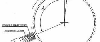
Many cars use a cooling fan powered by the engine. This fan is controlled by another type of clutch - a viscous clutch. It operates depending on the temperature of the liquid. The coupling is installed on the fan hub in the air flow passing through the radiator. This type of clutch is similar to a viscous clutch, which is used in all-terrain vehicles. When heated, the viscosity of the clutch fluid increases, causing the fan speed to increase to match the engine speed. In a cold car, the fluid in the clutch does not heat up and the fan rotates slowly, allowing the engine to warm up to operating temperature faster.
Many cars have limited slip differentials or viscous couplings, which are used to increase traction. When turning, one wheel rotates faster than the other, making steering difficult. The self-locking differential is operated using the clutch. If one wheel starts to spin faster than the others, the clutch is activated to slow down the rotation. Driving through puddles and ice can lead to slipping.
Chainsaws use centrifugal clutches to stop the chain without having to turn off the engine. These clutches operate automatically using centrifugal force. The input drum is connected to the engine crankshaft. The output drum drives the chain. As engine speed increases, the friction segments are pressed against the inner surface of the drum. Centrifugal clutches are also used in lawn mowers, go-karts and mopeds. Even some yo-yo toys have a clutch.
The clutch system is designed to connect the vehicle's engine to the transmission. In general, it can be called the connecting link between these two power units. In this article we will tell you what the principle of operation of the clutch is, what components the system consists of, and a visual video of the device’s operation.
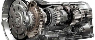
Manual transmission device
A manual transmission changes gear ratios using a combination of gears of different diameters mounted on the main and auxiliary shafts. The main drive rotates by the crankshaft, and the auxiliary drive rotates the cardan. The principle of operation of mechanical transmissions can be clearly observed on a bicycle derailleur. If a small gear on the drive and a large one on the secondary shaft are simultaneously engaged, then at the output we will get greater thrust, and if vice versa, then speed. As you can see, everything is extremely simple.
If we go deeper and disassemble the structure of a manual transmission in more detail, we can identify several main elements that mechanical transmissions have:
- input shaft;
- secondary shaft;
- clutch;
- final drive gears (often fourth speed);
- reverse gear;
- gears of other speeds;
- gear shift rods (there are three or four of them);
- gear clutches (also called gear locks);
- automatic gear shift blocker.
Manual transmission device
A manual transmission consists of a clutch basket and the gearbox itself.
The power unit includes:
- crankcase (housing);
- primary, secondary and intermediate shafts;
- stage selection device;
- driven and driving sets of gears;
- synchronizers;
- bearings, couplings and seals.
All these components are located in the housing and interacting with each other transmit torque.
Clutch
The clutch is an integral component of a manual transmission, which disconnects the engine and gearbox at the moment of gear shifting without consequences for the units. To exaggerate, the clutch turns off the torque, while both the engine and the wheels of the car spin at idle.
The clutch is designed to neatly connect the motor and wheels. It consists of two disks, one of which is connected to the car’s motor, the second to the wheels of the vehicle. The transmission of torque is carried out through the input shaft of the transmission.
The activation (release) and disengagement (squeezing) of the clutch is controlled through the pedal.
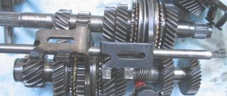
Gears and shafts
In standard manual transmissions, the shaft axes are located parallel, and gears are located on them.
The drive (primary) shaft is connected to the engine flywheel through the clutch basket; the longitudinal projections located on it move the second clutch disc and transmit torque to the intermediate gear through a rigidly fixed drive gear.
In the shank of the drive shaft there is a bearing, to which the end of the secondary shaft is adjacent. The absence of a fixed connection makes it possible for the shafts to rotate independently of each other in different directions and at different speeds.
The driven shaft has a whole set of different gears, both rigidly fixed and freely rotating.
The movement and selection of the required pair of gears for the distribution of torque corresponding to the conditions of movement is carried out by shift forks using a two-way control mechanism.
The gear shift rod consists of a lock, a gear shift clutch, drives, sliders with forks that move lengthwise and crosswise using the gearshift handle located inside the car, and a drive.
The gear selection mechanism can be located either in the transmission housing or on the body of the vehicle and, in rare cases, on the steering column. In most cases, a rocker mechanism is used to drive the gear rod.
Synchronizers
The angular velocities of the primary and secondary shafts are equalized with the assistance of the synchronizer and a stage change becomes possible. Synchronizers provide more gentle operation of the gearbox and reduced noise.
Special equipment and some sports cars are not equipped with synchronizers.
Operating principle of the gearbox
A manual transmission works on the following principle: the gear shift lever moves rods, which move the clutches. They, in turn, block certain gears on the input shaft (those are in a free position when the neutral position is turned on). A locked gear transmits rotation to the output shaft. Due to the fact that all the gears are of different diameters, the gear ratio changes, which makes the wheels rotate with more force or faster. The greater the effort, the lower the speed and vice versa. Therefore, the first gear in a manual transmission is called “traction” - it transmits more force to the drive, although it cannot provide a high speed to the car.
The “robot” with the “automatic machine” is not far from the previous one in terms of device. But with a CVT transmission everything is a little different. Here, to transmit rotation, a belt is used, which is placed over rings of different diameters attached to the drives. The advantages of this gearbox are convenience (no need to change gears manually) and efficiency (although it is far from a manual transmission). There is only one drawback: its use is pointless on powerful engines and heavy vehicles, the belt will wear out quickly, the drive will rotate, but the wheels will not.
Composition of the clutch assembly
Pressure plate
This element, popularly called “basket,” is the base of a convex round shape. The release springs are connected to a pressure pad (also round).
Driven disk
It also has a round shape, and its design consists of the following components: base, splined clutch, friction linings, damper springs. The latter are located around the coupling and serve the purpose of vibration damping. The friction linings are based on a carbon fiber composite; in addition, they can be made of ceramics, Kevlar, etc. They are attached to the base using special rivets.
Release bearing
One of its sides is a rounded pressure pad. It is located on the input shaft protruding from the gearbox and is mounted on the shaft protective casing. The drive fork drives the bearing by pressing on the latter's mandrel. The principle of operation of the bearing can be either pull-back or push-pull.
Drive system
It can be mechanical, electrical and hydraulic.
- In a mechanical system, the force exerted by pressing the pedal is transmitted to the release fork by a cable located inside the casing.
- The electrical system includes an electric motor to which a cable is connected and activated by pressing the pedal.
- The hydraulic system consists of a master and working cylinders connected to each other by a high-pressure pipe. Pressure on the pedal activates the master cylinder rod, at the end of which there is a special piston. The latter presses on the brake fluid, creating pressure that is transmitted to the working cylinder through the tube. The design of the working cylinder is similar: there is also a rod and a piston. Due to the pressure, the piston pushes the rod, which presses the release fork.
Clutch pedal
It is located near the gas and brake pedals and is always on the left. In cars with an automatic transmission, this element is absent, but the clutch mechanism itself does exist.
How does the five-step work?
The operation scheme is designed in such a way that the five-speed gearbox has a primary shaft, which rotates with the help of the engine crankshaft. The gears mounted on it are in a free position. The secondary shaft does not rotate. When a gear is engaged, the clutch is pushed by a special rod, which puts it on one of the gears. At this moment, the gear is locked and begins to rotate along with the input shaft. This rotation is transmitted to the secondary shaft gear, after which it also begins to rotate. As a result, the force is transferred to the wheel drive, and the car begins to move.
A five-speed manual gearbox operates on this principle. Its beauty lies in the fact that it allows significant fuel savings (compared to automatic transmissions), and an experienced driver will be able to “squeeze” better acceleration dynamics from a car with this type of gearbox.
Most often, “mechanics” are installed in budget cars due to their cheapness and in sports cars - this way pilots will be able to better control the movement of their car.
But in this case, not an ordinary five-speed gearbox is used, but a seven or even eight-speed gearbox. Although a four-speed gearbox was used quite widely in the past, it was later abandoned.
Five-speed gearbox
Five-speed gearbox (longitudinal section)
1 – input shaft; 2 – bearing cover; 3 – cuff; 4 – input shaft bearing; 5 – retaining ring; 6 – roller bearing of the secondary shaft; 7 – breather; 8 – blocking ring; 9 – clutch for engaging III – IV gears; 10 – synchronizer block; 11 – hub of the clutch for engaging III - IV gears; 12 – third gear gear; 13 – needle bearing; 14 – retaining ring; 15 – half ring; 16 – 2nd gear gear; 17 – needle bearing; 18 – switch rod; 19 – 1st gear gear; 20 – secondary shaft; 21 – reverse gear; 22 – fork for 5th gear and reverse gear; 23 – clutch hub for engaging 5th gear and reverse; 24 – retaining ring; 25 – bolt securing the retainer plate; 26 – fifth gear gear; 27 – thrust washer; 28 – secondary shaft bearing; 29 – protective seal; 30 – shift lever; 31 – retaining ring; 32 – speedometer sensor drive gear; 33 – shift lever housing; 34 – rear housing; 35 – steel-babbit bushing; 36 – cuffs; 37 – rear bearing of the intermediate shaft; 38 – intermediate shaft; 39, 44, 45 – gears V, II, III intermediate shaft gears; 40 – bolt; 41 – crankcase gasket; 42 – drain plug; 43 – front crankcase; 46 – filler plug; 47 – intermediate shaft drive gear; 48 – adjusting gasket; 49 – front bearing of the intermediate shaft; 50 – axis of the reverse intermediate gear; 51 – reverse intermediate gear; 52 – roller bearing of the gear; 53 – bolt securing the bushing of the idler gear axis of the reverse gear.
Description of design
The cars are equipped with a mechanical, five-speed, three-shaft gearbox with a fifth overdrive gear. Some cars with a ZMZ-402 engine can be equipped with a four-speed gearbox, previously installed on Volga cars GAZ-24, GAZ-3102 and -31029. See below for its description and repair.
The five-speed gearbox is unified in most parts with the gearbox installed on cars of the Gazelle and Sobol families. The differences between the Volga car’s gearbox are smaller gear ratios in all gears except fourth, as well as a smaller shift lever housing and a shortened lower end.
The gearbox housing consists of two parts - front and rear housings, cast from aluminum alloy and connected through a gasket with ten bolts in a plane perpendicular to the axis of the shafts. To ensure alignment of the bearing housings and the holes for the shift mechanism rods, the crankcases are centered with each other through mounting sleeves. The primary, secondary and intermediate shafts with helical gears of constant mesh are installed in the bores of the crankcases on radial ball bearings. The gears of the secondary shaft are placed on roller (needle) bearings with plastic cages. The gears of the second, third, fifth gears and the intermediate shaft drive are pressed onto the intermediate shaft and form a gear block. The teeth of the gears of the first gear and at the same time the reverse gear are cut directly on the intermediate shaft. The reverse helical idler gear receives constant rotation from the idler shaft when driving in all gears and in the neutral position of the shift lever. It is supported by a roller bearing on a fixed axis attached to both crankcases. All gears are equipped with inertial synchronizers. Their ring gears are connected to the gears through small splines. The switching mechanism consists of rods with forks and heads, in the grooves of which the lower end of the shift lever is located. The engaged gears are locked using spring-loaded balls. A locking device consisting of two plungers and a locking pin prevents two gears from being engaged at the same time. The shift lever is equipped with a damping device that prevents it from shaking (resonance) at high crankshaft speeds. The rear splined end of the secondary shaft is connected to the sliding yoke of the driveshaft. The fork shank fits into the steel babbit bushing of the rear gearbox housing extension and, moving in this bushing and along the splines of the secondary shaft, compensates for the axial travel of the cardan transmission when the rear suspension is operating. The drive helical gear of the speedometer sensor drive is installed on the secondary shaft. To fill and drain oil, filler and drain plugs with conical self-sealing threads are used. The drain plug has a magnet to catch transmission wear debris. Filler plugs are located on both sides of the crankcase.
Changing the oil and flushing the gearbox
We install the car on an overpass or inspection ditch. Drain the gearbox oil immediately after the trip, before it cools down.
Use a 12mm hex wrench to unscrew the drain plug...
...and drain the oil into a wide container with a capacity of at least two liters.
If the used oil is dark in color or there are visible metal particles in it, wash the gearbox by replacing the drain plug, clearing its magnet of steel shavings. Then…
... use a 12-point hex key to unscrew the filler plug on the right side of the crankcase (for a car with a ZMZ-406 engine) ...
...or on the left (with the ZMZ-402 engine).
Using an oil syringe, pour approximately one liter of a mixture of transmission or motor oil with 20-30% kerosene or diesel fuel into the box and replace the filler plug.
Having placed stops under the front wheels, we hang the rear wheel or the entire axle. Having engaged first gear, start the engine for 2-3 minutes. Having installed the car on wheels, completely drain the flushing oil (draining time is at least 5 minutes). Having cleaned the drain plug again, screw it into place with a key. Having unscrewed the filler plug, use an oil syringe to fill the gearbox with fresh transmission oil to the level of the filler hole (1.2 l). Having installed the filler plug in place, turn it with a key. Instead of a syringe, you can use a funnel with a hose.
Replacing the speedometer sensor
Having released the wire from the bracket...
...disconnect the speedometer sensor connector.
Using a 10mm wrench, unscrew the bolt and remove the sensor locking plate.
Using the “22” key, unscrew the speedometer sensor. Install the new sensor in reverse order.
Replacing the reverse light switch
After removing the protective rubber cover, disconnect the wires from the switch terminals.
Using the “22” or “24” key (depending on which sensor is installed), turn off the switch.
If necessary, replace the O-ring on the new switch and install it in the reverse order.
Replacing the front input shaft bearing
Remove the gearbox and clutch (see relevant sections).
We press the spacer sleeve of the puller into the bearing.
Holding the puller with a “15” wrench and a “22” socket, tightening the bolt,...
...press out the bearing. If there is no puller, remove the flywheel and knock out the bearing through a mandrel.
Having selected a suitable head, bushing, etc., we press in a new bearing.
We assemble all the nodes in reverse order.
Replacing gearbox seals
There are three cuffs installed in the gearbox: one in the input shaft bearing cap and two in the rear housing extension. Remove the gearbox and clutch (see relevant sections). Remove the bearing cover (see Disassembling the gearbox). If you need to replace the cuffs of only the rear crankcase, remove the cardan transmission (see Removing and installing the cardan transmission), leaving the box on the car.
Using a screwdriver, remove the cuff from the cover.
Having filled the cavity between the working edge and the boot of the cuff with Litol-24, we press it in using the “36” head as a mandrel.
Using a screwdriver, we sequentially remove both cuffs from the rear housing extension.
Having lubricated the working edge of the new cuffs with Litol-24, we press them through a suitable head or an old cuff.
We install the dismantled units (see the relevant sections). After replacing the rear cuffs in the box without removing it from the car, check the oil level and add it if necessary.
Removing the gearbox
We work on a lift or inspection ditch, preferably together. Drain the oil from the gearbox and disconnect the electrical connectors from the reverse light switch and speedometer sensor (see Changing the oil and flushing the gearbox and other relevant sections). Remove the decorative plastic ring and lift the rubber seal of the gearbox lever (see Removing the instrument panel).
Using sliding pliers, unscrew the cap nut securing the lever to the gear shift mechanism...
...and remove the shift lever from the housing.
We take out the rubber floor seal.
We remove the cardan transmission and exhaust pipes (see the relevant sections).
The gearbox weighs about 32 kg, so it is better to remove it with two people. If there is no assistant, to be on the safe side, support the box with a hydraulic stop or a reliable stand.
To prevent the engine from moving backwards, a suitable sized block of wood can be inserted between the cylinder block and the body panel.
Using a 19mm wrench, unscrew the four nuts securing the gearbox to the clutch housing.
While holding the box, use a 14mm wrench to unscrew the four bolts securing the rear support of the power unit to the body.
Supporting the box, remove the stop and tilt the engine back.
We move the box back and remove it from the car.
It is recommended to install the gearbox with an assistant, since it is necessary to hold the heavy unit above your head and align the holes in the clutch disc and flywheel bearing with the input shaft, and the bearing cover with the hole in the clutch housing. The installation sequence is the reverse of removal.
Gearbox disassembly
We unscrew the speedometer sensor (see the corresponding section).
Using a 12mm wrench, unscrew the four bolts securing the gear shift mechanism cover.
Remove the cover with the sealing gasket.
Using a 12" wrench, unscrew the three bolts securing the bearing cover...
...and remove the cover along with the gasket.
Use two screwdrivers to remove the retaining ring of the input shaft bearing.
Using a 13mm wrench, unscrew the bolt securing the reverse intermediate gear axis to the gearbox housing.
Using a 10mm wrench, unscrew the ten bolts connecting the front and rear gearbox housings.
We disconnect the crankcases by tapping with light blows of a hammer through a wooden mandrel on the lugs securing the gearbox to the clutch housing.
Do not strike the input shaft, as this will damage the synchronizer. Also, do not lose the adjusting shims located in the crankcase bore, under the secondary shaft bearing.
Using a 13mm wrench, unscrew the two bolts securing the rod clamp plate.
After removing the plate, use tweezers to remove the clamp springs.
Using a 10mm wrench, loosen the three bolts securing the forks to the rods.
To unscrew the bolt securing the last fork, move the fifth gear and reverse rod forward.
Using a copper hammer we knock out the rods of I-II and V gears. The last thing we knock out is the rod of III-IV gears.
Having removed the rods from the holes in the crankcase, we remove the gear shift forks from the grooves of the couplings. It is recommended to immediately put the forks on the rods of the corresponding gears, so as not to confuse them during subsequent assembly.
In order not to lose the retainer balls, use a screwdriver to push them inside the crankcase, first placing your palm under it.
To prevent the rod locks from falling out, we fix them with any grease.
Using a 13mm wrench, unscrew the second bolt securing the reverse intermediate gear axis to the gearbox housing.
Using pliers, we open the retaining ring of the outer bearing of the secondary shaft and, applying gentle blows to the end with a brass hammer, press out the secondary shaft,...
...at the same time removing the shaft and axis of the reverse intermediate gear from the rear gearbox housing.
We separate the primary and secondary shafts. When doing this, be careful not to lose the 14 rollers of the front output shaft bearing.
Having installed the secondary shaft vertically in a vice, use pliers to open the retaining ring of the hub of III-IV gears.
Remove the retaining and spring rings.
Using two screwdrivers, we move up the third gear gear together with the clutch and hub of the fourth gear.
Remove the 3rd-4th gear clutch from the shaft along with the hub.
Remove the blocking ring and the 3rd gear gear.
Remove the needle bearing.
Remove the retaining ring of the two thrust half-rings of the secondary shaft...
...and remove both thrust half-rings.
Using a thin screwdriver, we remove the locking ball from the secondary shaft.
Remove the 2nd gear gear.
In the same sequence, we continue to disassemble the entire set of gears and secondary shaft couplings up to and including removing the first gear. We continue further disassembly of the secondary shaft from the other end.
Using two large screwdrivers, press the intermediate shaft bearing.
When disassembling the shafts, we recommend that you lay out all the parts in the order in which they were removed - this will make subsequent assembly easier. Parts that have not been replaced must be installed in their original places, maintaining, as far as possible, their relative position relative to other parts. Before assembly, check the condition of the gearbox parts. Cracks of any shape and length are not allowed on crankcase parts. The bearing housings, the holes for the shift rods and the steel babbit bushing of the rear housing extension must be smooth, without nicks, signs of scuffing or noticeable wear. The bearings should fit into the sockets tightly, by hand force or by lightly tapping through the spacer. The crankcase gaskets must be intact, without ruptures, delaminations or breaks. We check shafts, axles and rods for cracks, noticeable signs of wear, scuffing and metal envelopment. This also applies to the splined parts of the shafts; the mating parts should move easily on the shafts, without noticeable play or jamming. Remove minor traces of scoring, as well as possible corrosion (on the splines), with a velvet file and very fine sandpaper, and polish the shaft journals with thin GOI paste or diamond paste. On the teeth of gears and synchronizer couplings, chips, traces of jamming and chipping are not allowed; on the cones of synchronizers there should also be no traces of jamming, severe wear and enveloping of bronze on steel. Ball and roller bearings must be in perfect condition. Their rotation should be easy, without jamming, clicking, play or vibration. Fatigue chipping (pitting), noticeable wear and chips are not allowed on raceways, balls and rollers (needles). Ball bearing cages must not touch the rings or have cracks or breaks. In general, after a run of about 120 thousand km, it is better to replace ball bearings with new ones, regardless of their condition. We also replace the cuffs of the sliding fork of the propeller shaft and the cuff of the input shaft, regardless of their condition. Before assembly, thoroughly wash all parts in kerosene or diesel fuel, and degrease the crankcase threaded holes with acetone or solvent for nitro paints. We coat the rubbing surfaces of the gear shift mechanism, the steel-babbit bushing, cuffs and splines of the secondary shaft with CV joint-4 lubricant, and the rest with transmission oil. Bearings and their seats should also be lubricated with transmission oil before assembly. We assemble the box in reverse order. To ensure the assembly of full complement bearings, generously coat their needles and rollers with any grease.
During assembly, we install all the shafts into the rear gearbox housing at the same time. To facilitate this operation, the shafts can be tightened with a belt.
The thickness of the gasket between the gearbox housings determines the amount of axial clearance in the intermediate shaft bearings. Therefore, we must install it, lubricating it with a thin layer of sealant for reliability. All other gaskets between the crankcase parts should also be lubricated with sealant.
During assembly, the crankcase connection bolts should be degreased and the threads should be coated with sealant. After installing the unit on the car, do not forget to fill the box with 1.2 liters of transmission oil (to the level of the filler hole).
Why is it impossible to engage two gears at the same time?
Physically this cannot be done, because the shift lever can only be in one position. But this problem was present until a speed blocker was invented. The blocker is very simple - it is a small ball that rolls between the rods in a special chamber and when one is turned on, it completely blocks the movement of the other. As they say, everything ingenious is simple, and such an important thing as a blocker is also an elementary thing.
Mechanical box for dummies. 9 important details
A beginner who has purchased a car with a manual transmission needs to become familiar with the important nuances in handling the transmission and understand some points. Let's start in order. What are the transfers for? In order to choose which one and under what conditions will be best for use in the situation you require (weather conditions, quality of road surface, etc.)
1. Start the engine. Scheme: “neutral” - clutch - engine start. And nothing else.
2. Correct use of the clutch. Squeeze strictly until the end and no more than 2 seconds. We take care of the car.
Synchronized and non-synchronized gearbox
From the very beginning, the mechanical transmission was designed in such a way that all the gears in it were constantly rotating. Otherwise, the car driver simply would not be able to change gears. Under the influence of rotation of the drive, the teeth of the gears in the gearbox would not touch each other. But even this approach could not save them from frantic wear and the appearance of very loud sounds when switching, since the teeth rubbed against each other at the moment of switching, and the metal made heartbreaking groans.
In 1952, Porsche decided to take a different approach: the gears were locked at the moment of gear shifting. And the synchronization of the teeth was carried out using an additional gear with bevel teeth, which helped to better align them. It was then that a five- and six-speed type of gearbox appeared, since this innovation made it possible to increase the number of steps in the gearbox, and the designers were able to move away from the usual four speeds.
By the way, without moving away from the topic of history, let us thank the genius who thought of drawing a decoding of the location of the gears on the shift handle itself. By doing this, he saved many beginners from serious damage on their very first trip.
The design and principle of operation of a car clutch[ | ]
Automotive single-plate clutch design
1
- flywheel
2
- linings made of friction material
(ferodo) 3
- driven clutch disk
4
- springs pressing the drive disk to the flywheel
5
- clutch release fork
6
- push clutch
7
- clutch pedal
8
- clutch pedal
9
- drive (pressure) disk
10
— engagement lever (or release lever, 3 pieces in the figure)
11
— release (thrust) bearing
12
— drive (input) shaft of the gearbox
Single disc clutch[ | ]
Operating principle:
When you press the pedal 8
Shaft
7
is rotated, first the gap (
free play of the clutch pedal
) is selected between the clutch release fork
5
and the push clutch
6
.
Then the clutch with the release bearing 11
moves and the release bearing presses on the inner ends of the levers
10
, which with their outer ends move the pressure disk
9
from the driven disk
3
.
In this case, the pressure springs 4
are compressed - the clutch is disengaged, and torque is not transmitted from the engine to the transmission.
After releasing the pedal, the clutch release clutch with the release bearing returns to its original position under the action of springs. Under the action of pressure springs, pressure plate 9
is pressed against flywheel
1
, while squeezing driven disk
3
- the clutch is engaged, torque is transmitted from the engine to the gearbox.
The driven disk 3
has splines and moves along the mating splines of the input shaft of the gearbox
12
. Smooth transmission of torque when the clutch is engaged is ensured by damper springs mounted in the driven disk.
All clutch parts are covered with a casing (clutch basket), which is bolted to the flywheel; The axles of the release levers are attached to the casing through eyes.
The clutch of motorcycles with a longitudinal engine is not fundamentally different.
- The release bearing is usually a special thrust ball bearing; On some cars, thrust bearings (graphite) are used, in this case the term thrust bearing
(Zaporozhets cars; Moskvich-412, except for later releases).
Diaphragm spring clutch[ | ]
Diaphragm type clutch. 1
- crankshaft
2
- flywheel
3
- clutch driven disc
4
- pressure plate
5
- diaphragm spring
6
- gearbox input shaft 7 - push clutch and release bearing
8
- clutch housing (clutch basket)
9
- connections
10
- studs
11
- stops
Passenger cars typically use a diaphragm spring clutch instead of a large number of engagement levers and coil springs. The clutch spring is flat or has the shape of a truncated cone; petals (about two dozen) are stamped in its central part, which simultaneously serve as release levers. When you press the pedal, the clutch release fork moves the pressure clutch and release bearing 7
, the inner edge of the spring moves forward, the spring bends and its outer edge retracts the pressure plate
4
, the clutch is disengaged. When the pedal is released, the parts move in the reverse order, the diaphragm spring returns to the shape of a truncated cone, and the clutch is engaged. A diaphragm spring clutch is lighter and cheaper than a lever clutch and requires fewer adjustments during repairs.
Double-disc clutch[ | ]
Diagram of a double-disc clutch
On heavy trucks, tractors, armored vehicles, on some heavy motorcycles (Ural, Dnepr), as well as on some sports cars, double-disc clutches are used.
Double-disc mechanisms are installed to increase clutch life, due to the high power of engines and the need to transmit increased torques.
General design of a double-disc clutch[ | ]
- Engine flywheel friction surface - blue color on the left
- Two driven discs - brown
- Intermediate drive disc - blue
- Pressure drive disk - green color
- Compression Springs - Gray
- Housing - blue color on the right
Not shown in the figure[ | ]
- Forks
- Clutch release levers
- Release bearing
- Clutch release fork
- Release springs
Operating principle of a double-disc clutch[ | ]
The release bearing pushes the release levers, they pull back the pressure plate. The pressure plate moves away from the first driven one and releases the release springs. They release the intermediate drive disk, and due to other release springs it moves away from the second friction one, as much as the pressure one moves away from the first friction one. During the reverse movement, the release springs help to uniformly press the intermediate disk against the second driven one and the pressure disk against the first driven one.
The pressure plates move along studs screwed into the flywheel, and the clutch basket is also attached to them. Release springs are placed on the studs.
Pneumatic clutch booster[ | ]
Heavy trucks, for example MAZ, have a clutch drive with a pneumatic booster - designed to reduce the force applied to the clutch pedal.
Device: pedal, rod, spool (control valve), hoses, pneumatic chamber, levers, brake, input shaft with brake drum. Operating principle: when the pedal is released, the inlet valve of the spool is closed and the outlet valve is open. When you press the pedal, the force is transmitted through the rod and spool to the clutch release fork. At this time, the inlet valve in the spool opens and the outlet valve closes - the spool body slides onto the outlet valve, the outlet valve is pressed against the inlet valve and closes, and the inlet valve opens with this movement. Air enters the pneumatic chamber through the inlet valve, which, due to pressure, helps to press the clutch release fork.
Conical clutch[ | ]
The oldest type of clutch, widely used on many cars of the early 20th century. The friction surfaces had a conical shape. It transmitted more torque with the same dimensions compared to a single-disc one; it was simple in design and maintenance. However, the heavy disk of such a clutch had high inertia, and when changing gears after depressing the pedal, it continued to rotate at idle, which made engaging the gear difficult or simply impossible. To brake the clutch disc, a special unit was used - the clutch brake, but its use was only a half-solution to the problem, as was the replacement of one cone with two less massive ones. In addition, the clutch was heavy and bulky. As a result, it was abandoned in the 1920s.
There was also a reverse cone clutch that worked to release.
Transmission synchronizers are essentially bevel clutches that operate by rubbing bronze (or other high-friction metal) against steel.
Why is the shift lever long and short, and why is it sometimes placed on the steering wheel?
We are sure that you have repeatedly seen that in addition to the usual long lever, a short one is also used. Have you ever wondered why it was done this way? It's all about which wheels the car has that are driving. As a rule, in cars with rear-wheel drive, the manual transmission is located directly under the shift lever and the latter enters directly into it. For cars with front-wheel drive, everything is a little different: the gearbox is not installed under the passenger compartment, so an extension cord is stretched to it, which connects the shift lever and the box itself.
In American films, we have all repeatedly seen that in old pickup trucks, gear shifting is carried out by one of four levers on the steering column. It is placed there for ease of switching, and the gearbox is located in the engine compartment under the hood and an extension cord is attached to it. It's that simple.
By the way, about the length of the manual transmission lever, it must be said that it differs depending on how much force you need to apply to change gears. In cars with a short lever, shifting occurs with less effort, so there is no need to use a lever to make shifting easier for the driver.
Operating principle of clutch actuators
The principle of operation of the car's clutch drive, with which the force from the pedal is transmitted to the shift mechanism, can be mechanical, hydraulic or electric.
Mechanical
The clutch drive is structurally the simplest: it is a steel cable connecting the pedal rod and the clutch lever. There is usually a threaded connection on it, which can be used to adjust the length of the cable. The disadvantage of this drive is that it requires more force when pressing the pedal.
Hydraulic
the drive is more comfortable to operate, especially if you have to use the clutch frequently. Its operating principle is similar to the operation of the brake system: when you press the pedal, the piston presses on the fluid, which, moving in the cylinder, sets the clutch lever pusher in motion. In this case, the pedal stroke is softer, but you need to monitor the condition of the hydraulic hoses and control the level and quality of the hydraulic fluid poured into the system.
Electric
The drive differs from a mechanical one in that the clutch release cable is driven by an electric motor, which is activated when the pedal is pressed. Otherwise, its design is not much different from a mechanical drive.
In practice, working with a car’s clutch is mainly expressed in developing the skill of properly starting off, especially on an uphill slope. In busy city traffic, skillful use of the pedal will allow the car to move smoothly and not stall during sudden braking.
When starting to move, you need to release the clutch pedal, catch the moment of contact of the discs, balance the speed of their rotation, and then smoothly release the pedal. The reference point is the engine speed. If the engine runs smoothly, the clutch engages correctly.
The clutch should only be used when starting, changing gears and when stopping the vehicle. Compliance with this requirement will extend its service life.
- A sharp or, conversely, slow release of the clutch pedal at start leads to accelerated wear of the working surface of the discs.
- Stopping at a traffic light with the pedal pressed and the gear engaged will not have the best effect on the operation of the pressure springs, bearing and release fork.
The two main malfunctions of the clutch mechanism are insufficiently tight contact of the discs and insufficiently complete separation of them.
- In the first case, the clutch slips, and the car will experience poor acceleration dynamics. This is usually the result of wear on the driven disk and its friction linings.
- In the second case, as a result of incomplete separation of the disks when the gear is engaged and the pedal is pressed, the car tries to move.
If these malfunctions cannot be eliminated by adjusting the drive, then repair of the mechanism itself is necessary under stationary conditions.
Why do manual transmissions break down?
Let's give a couple of tips for dummies:
- Speeds are switched on “by force”. Most likely, either the clutches or synchronizers are worn out. The teeth are no longer cone-shaped, which prevents them from entering the hook normally.
- Speeds turn on independently. The blocker is faulty. The ball, which serves as a blocker, begins to move freely in the grooves, which allows the gears to engage spontaneously.
- “Knocks out” the scenes. The problem is still in the same blocker.
- The gearbox is noisy. You urgently need to check the parts for wear. Pay special attention to the gear teeth, but it is also worth checking the bearings.
- Oil is leaking. Gaskets are often to blame. In addition, you need to check all the bolts on the gearbox housing cover, and when screwing them in, be sure to coat them with a thread locker.
Start
To move the car, you must first of all put the gear in the desired position and open the fuel supply for more efficient acceleration. It turns out that everything is not so complicated - clutch, first gear and gas. When a car starts to take off, it spends a lot of effort moving from a standstill, which is why the engine often stalls. The basis for smoothly starting a car is to simultaneously press the gas and clutch pedals. This is not about how to use the pedals, but about the use of the gearbox. Motorists prefer to start in first gear; this is very important, because the likelihood that the engine will stall is minimal. To engage the gear, you need to fully depress the clutch pedal, while moving the lever smoothly. If the resistance is very sharp and the transmission makes strange sounds, return the manual transmission lever to its original position. Release the clutch again and press the pedal, preferably repeat. When you turn on the desired position, the force of the lever will decrease slightly, and then its movement will stop. This will happen because at the end of the puzzle he will collide with a limiter. For driving in the cold season or during frosts, it will be very useful to learn how to start in second gear. This process will help prevent the wheels from slipping and skidding or burying themselves in the snow. There aren't that many differences. On a manual transmission, you need to select second gear so that there is no increase in the load on the engine; balancing with the gas and clutch pedals should be relatively subtle. The gearbox is negatively affected by: 1) abrupt shifting of the gearshift lever 2) sudden removal of the foot from the clutch pedal 3) high fuel supply. Such actions can very quickly lead to malfunctions.
Types and types of mechanical gearbox
There is its own classification of manual transmission. Let's look at everything in more detail. According to the method of engagement, boxes can be divided into:
- cylindrical gears. They have such advantages as reliable operation and long service life. In turn, they can be chevron, oblique and straight-toothed. Straight teeth are easy to manufacture, but cause considerable noise during operation. All this leads to rapid wear. Helical gears are characterized by particularly smooth shifting, low noise and high performance characteristics. Chevron gears are particularly smooth in operation;
- bevel gears. Their axes of the input and output shafts intersect, which allows you to change the direction of kinetic energy;
- worm-type They have low efficiency, but high gear ratio;
- wave They are wear-resistant with a high gear ratio;
- chain;
- screw.
According to friction, a manual gearbox can be either belt or friction.
Positive and negative points when using a car with a manual transmission
The advantages of a manual transmission include the following:
- Saving. Firstly, “mechanics” allows you to save on oil, the consumption of which is half that of a car equipped with an automatic transmission. Secondly, it saves fuel, but under one condition: you must know some of the nuances of driving such a car. On the section of the road where the descent begins, you need to put the gear in neutral so that the car rolls on its own. Only, unfortunately, such a technique is considered illegal and contrary to traffic rules. Well, and thirdly, this is the difference in money that will have to be spent when forced to repair the box. Almost any service station will be able to repair your manual transmission, since the simple design with the absence of complex components that an automatic transmission is equipped with does not require special in-depth knowledge (and, as a result, a small price for faulty parts). This fact, undoubtedly, allows you to independently understand the breakdown and fix the problem yourself (numerous videos on the Internet will come to the rescue here). And the “mechanics” itself is considered quite reliable, unlike the “automatic”;
- A simple principle of operation that even a driver without experience can comprehend;
- “Mechanics” allows you to accelerate the car faster, due to the fact that you yourself decide when it is better to change gear. “Automatic”, on the contrary, switches it to a certain speed automatically (although modern “automatic” ones are not inferior in dynamics to manual transmissions);
- In the winter season, it is easier to start a car with a manual transmission - a small volume of oil in severe frost does not have the same viscous properties as the same oil, but in double volume, accordingly, the resistance will also be less;
- Slipping will not affect the condition of the car as a whole, while a car with an automatic transmission really does not like to slip, since this causes increased overheating of the oil, so drifters prefer “mechanics”;
- Having learned to drive a manual transmission, the driver can easily switch to an automatic transmission. If you learn directly from an automatic transmission, then driving a manual transmission will be difficult.
This is interesting: A few words about 2AR-FE and its “brothers”
Naturally, manual transmission also has its disadvantages:
- Sometimes (especially on domestic cars and light trucks) in order to change gear, you need to apply quite a lot of force. Although in foreign cars the gears are easily changed, constant use of the lever is tiring, especially when driving in traffic jams;
- You have to be distracted by changing gears (although experienced drivers don’t notice this), with an “automatic” nothing interferes with the driving process;
- Novice drivers can burn out the clutch when driving a manual transmission (especially if they start uphill). A damaged clutch will have to be replaced, and this is not a cheap pleasure;
- Many people do not know this nuance, but the overall service life of the engine directly depends on the type of gearbox installed on the car. The automatic transmission changes gears more smoothly, which has a positive effect on the condition of the engine.