Table of torque for 402 engine. You can watch from the phone.
Why do I need a wide range of torque?
In order that all dynamic keys have an error. Better to take a moment in the middle of the range. The minimum allowable maximum torque. For example: 100-110 N · m.
Warning! Deliberate inaccuracy.
Since — 1 kilogram-force meter (kgf m) = 9.80665 newton meters (N m) In places with large moments, more accurate values are given. An example of more accurate calculations: 8.5 - 9.0 kgf m = 83 - 88 N m
List of tightening torques (table):
— Bolt mounting bracket front engine mounts. 2 points. M10. 25-32 N · m — A nut of fastening of an arm on a forward support of the engine. 4 points. M10x1. 28-36 N · m — Bolt of fastening of a cover of distributive gear wheels. 3 points. M8x1. 11-16 N · m — Nut of fastening of a cover of distributive gear wheels. 6 points. M8x1. 12-18 N m - Nut of fastening of a cover of a box of pushers. 2 points. M8x1. 12-18 N m
— Nut mounting cylinder head (cylinder head 402). 10 points. M12x1.25. – first stage 40-45 N · m – the second stage 83 — 88 N · m
Clean the oil tapped holes. Degreased surface. Better to break into more stages. There is no hurry.
Since I have not dealt with a 402 engine, I quote from the Internet: “After two or three starts and the engine is warming up to operating temperature, the head 402 will have to be pulled again. And after a run of 5000 km, perform the third train."
— Bolt of fastening of a cover of an opening of a water shirt of a head of the block of cylinders. 4 points. M8. 11-16 N · m — Nut fastening brackets for lifting the engine. 1 point M10x1. 28-36 N m - A nut of a bolt of a rod (A nut of fastening of a cover of a rod). 8 points. M10x1. 67-74 N m — Lock nut fastening the connecting rod cap. 8 points. M10x1. 3-5 N · m — Nut of fastening of a flywheel. 4 points. M11x1. 76-81 N · m — Bolt of fastening of a pulley of a cranked shaft. 6 points. M8. 11-16 N m - A nut of fastening of the holder of a back epiploon. 2 points. M8x1. 12-18 N m - Bolt fastening thrust flange camshaft. 2 points. M8. 11-16 N m - Bolt fastening gears camshaft. 1 point M12x1.25. 55-60 N · m — Bolt of fastening of a tube of lubrication of distribution gears. 1 point M6. 4.5-8 N · m — Nut of fastening of a rack of an axis of yokes. 10 points. M8x1. 35-40 N m - Bolt fastening cover rocker. 8 points. M6. 4.5-8 N m
— A nut of fastening of a collector to an inlet pipe. 4 points. M10x1. 44-56 N m - Gasket mounting nut. 9 points. M10x1.25. 40-56 N · m — Nut of fastening of the pallet of an oil case. 21 point. M8x1. 12-15 N m - Bolt of fastening of a cover and branch pipe of the oil pump. 4 points. M8. 11-16 N · m — Nut of fastening of the oil pump. 2 points. M8x1. 18-25 N m - Bolt mounting drive sensor-distributor. 1 point M6x1.25. 6-8 N · m — Nut of fastening of the oil filter. 4 points. M8x1. 12-18 N m — Nut carburetor mounting. 4 points. M8x1. 18-25 N · m — Bolt of fastening of the fuel pump. 2 points. M8. 12-18 N m — Nut filter mounting fine fuel. 1 point M8x1. 12-18 N · m — The bolt of the thermostat housing cover. 3 points. M6. 4.5-8 N m - Nut fastening distribution pipe. 2 points. M8x1. 11-16 N · m — Bolt of fastening of a cover of a case of a pump of a cooling liquid (water pump). 1 point M6. 4.5-8 N · m — Nuts of fastening of the water pump. 5 points. M8x1. 18-25 N m - Bolt fastening pulley water pump. 4 points. M8. 12-18 N · m — Bolt of fastening of the bottom of the clutch housing. 4 points. M8. 11-16 N · m — Bolt fastening the upper part of the clutch housing. 2 points. M10. 28-36 N · m — Nut fastening the top of the clutch housing. 6 points. M10x1.25. 40-56 N m - The clutch bolt to the flywheel. 6 points. M8. 20-25 N · m — A nut of fastening of an arm of the generator. 2 points. M12x1.25. 44-62 N m — Generator mounting nut. 2 points. M10. 44-56 N · m — Bolt of fastening of a lath of the generator. 1 point M8. 12-18 N m - Spark plug. 4 points. M14x1.25. 30-40 N m - Starter mount nut. 2 points. M12x1.25. 44-62 N m - Ratchet. 1 point M24x2. 14-16 N · m — Nut of fastening of covers of radical bearings. 10 points. M14x1.5. 98-108 N m - Nut carburetor mounting. 4 points. M8x1. 5-10 N m - Air filter mounting nut. 3 points. M6. 7.5-10 N m - Nut mounting screen heating air. 2 points. M8x1. 12-16 N m - Fan mounting bolt. 4 points. M8. 14-18 N · m — Bolt for mounting the bracket to the head cover (to the rocker cover). 2 points. M6. 5.5-8 N · m — A nut adjusting a cable tip. 2 points. M12x1.25. 40-56 N m
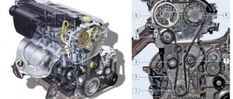
List of fuel injection and ignition control system components
| No. | Name | Designation | Manufacturer |
| 1. | Nozzle | 0288150560 or ZMZ 9261 DEKA ID | F. Bosch F. Siemens |
| 2. | Idle speed control | РХХ 60. or .9E2.573000 РХХ 60 | RF RF |
| 3. | Throttle position sensor | 0.280122001 or 406.1130000-01 | F. Bosch RF |
| 4. | Absolute pressure sensor | ATRT SNSR-0239 or А2С5325796 | F. Siemens RF |
| 5. | Phase sensor | 406.3847050-01 SMV 2.030-00 or 406.3847050-03 | RF RF |
| 6. | Knock sensor GT305 | ABKZH 402152.006 | RF |
| 7. | Timing sensor | 23.3847 or 406.3847060-01 | RF RF |
| 8. | Coolant temperature sensor | 234.3828 | RF |
| 9. | Throttle with sensor | 4062.1148100-30 | RF |
| 10. | Ignition coil | 406.3705, 3012.3705 or 405.3705 | RF RF |
| 11. | Spark plug | LR 15YC | F. Brisk (Czech Republic) |
Appendix 2
Depressurization of valves
Drying the valves Before attempting to remove the crackers, be sure to lightly tap them by passing a hammer over the valve plates (for example, through the long head) so that the crackers come off both from the plate and from the valve.
.. next we take a desiccant and tweezers or a ruler with a magnet (in our case there was a medical clamp) and a nut, screw the nut onto the nearest stud
We install the desiccant, resting one end of it against the nut screwed onto the stud. We compress the valve spring with a desiccant and pick out the crackers.
It is more convenient to desiccate the cylinder head when it has not been removed from the engine, because it will not go anywhere under the pressure of the desiccant.
List of electrical equipment
| No. | Name | Designation | Manufacturer |
| 1. | Generator | 94023701-17 TU 37.460.113-2001 or 33.3771010 TU 37.463.158-99 | RF |
| 2. | Starter | 4216.3708000-01 TU 37.003.1341-87, 5732.3208000 TU4573-016-05808959-2005 or 422.3708000 TU 37.003.1306-86 | RF |
| 3. | Oil pressure indicator sensor | 234.3829 TU 37.459.179-95 | RF |
Removing the cylinder head
Remove the front coolant flange
Inner timing case
Remove the connectors from the sensors Remove the right coolant flange
Fuel hoses
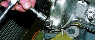
Unscrew the cylinder head mounting bolts
Removing the cylinder head
It is recommended to replace the cylinder head bolts with new ones!
Cylinder head with manifolds:
Rolling bearings
| No. | Name | Designation | Qty |
| 1. | Ball Roller Water Pump | 6-5НР17124ЭС30 | 1 |
| 2. | Ball Tensioner Roller | 60203A | 2 |
| 3. | Guide end of the gearbox drive shaft, (in the crankshaft socket) | 60203 | 1 |
Cylinder head assembly
We assemble the cylinder head in the reverse order. We put the valves in place, observing the correct location, install the lower valve support washers, oil seals, valve springs, upper support washers and dry the valves.
It is convenient to place a nut under the valve to be dried so that it does not fall down.
We install the collector, having previously cleaned the mating surfaces of the parts
New exhaust manifold gaskets.
Next we put the camshaft in place.
13. Installation of new valve stem seals
Soak the caps in engine oil
We put a protective cap on the valve (included with the MSK), put a new valve stem seal in the MSK puller and hammer it into place
Cuffs and seals
| No. | Name | Designation | Qty |
| 1. | Front crankshaft cuff | 53-1005034 | 1 |
| 2. | Rear crankshaft cuff | 2108-1005160 | 1 |
| 3. | Water pump seal | 2101-1307013-01 or 2108-1307013-03 | 1 |
| 4. | Intake and exhaust valve oil seal | 417-1007036 or 402.1007026 | 8 |
Removing the valve cover and camshaft
Unscrew 8 nuts
The valve cover gasket must be replaced
Removing the oil shield
The lid is covered with a layer of tar. They didn't wash it too hard. We soaked it in solvent and went through it with a carpet brush.
Removing the camshaft:
We loosen the nuts of the shaft bed covers diagonally and evenly:
We remove the bed covers, remembering their location and orientation:
We remove the shaft.
Tightening torques for critical connections of the 4216 engine
| Compound | Torque, N×m (kgf×m) |
| Main bearing cap nuts | 122,6-133,4 (12,5-13,6) |
| Nuts of connecting rod cap bolts | 66,7-73,5 (6,8-7,5) |
| Nuts for fastening rocker arm axle structures | 34,3-39,2 (3,5-4,0) |
| Oil filter mounting fitting | 78,4-88,2 (8,0-9,0) |
| Spark plug | 29,4-34,2 (3,0-3,5) |
| Oil filter | 19,6-22,5 (2,0-2,5) |
| Cylinder head stud nuts | 88,3-93,2 (9,0-9,4) |
| Oil crankcase nuts | 9,8-11,8 (1,0-1,2) |
| Flywheel to crankshaft bolts | 79-88 (8,0-9,0) |
| Bolts securing the clutch disc to the flywheel | 20-29 (2,0-3,0) |
| Fuel rail mounting nuts | 13,7-17,6 (1,4-1,8) |
Replacing the cylinder head gasket for UAZ 31519
The cylinder head gasket is replaced if damaged.
The main signs of damage to the head gasket:
– insufficient compression – below 1 MPa (10 kgf/cm2) in one or more cylinders;
– breakthrough of gases into the cooling system (seething, foaming of liquid in the radiator, rapid drop in the liquid level in the expansion tank in the absence of external leaks);
– coolant entering the lubrication system (emulsion on the oil level indicator, stratification of oil drained from the crankcase, which is especially noticeable in a transparent container);
– oil getting into the cooling system (oil film on the surface of the liquid in the expansion tank).
To replace the gasket, you need to remove the cylinder head with the receiver and exhaust manifold. If the cylinder head is removed from an engine installed on a vehicle, the coolant must first be drained (see “Replacing the coolant”).
You will need: keys “12”, “13”, “17”, hexagons “6”, “12”, screwdriver.
1. Disconnect the wire from the negative terminal of the battery.
2. Drain the cooling system (see “Replacing the coolant”).
3. Remove the generator (see “Removing and installing the generator on cars with a gasoline engine”).
4. Unscrew the four pairs of nuts securing the exhaust pipe to the exhaust manifold.
5. Remove the bolt securing the exhaust pipe to the bracket on the gearbox and move the exhaust pipe away from the exhaust manifold.
6. Disconnect the wiring harness connectors from the mass air flow sensors.
7. . throttle position.
8. . and crankshaft position.
9. Loosen the clamp securing the air supply pipe, remove the pipe and move it to the side.
10. Disconnect the end of the cable from the throttle drive sector.
11. Loosen the fastening of the end of the cable braid to the bracket.
12. ...remove the end of the cable braid from the bracket and move the cable to the side.
13. Remove the cylinder head cover (see “Replacing the cylinder head cover gasket”).
14. Remove the upper chain hydraulic tensioner (see “Removing and disassembling hydraulic chain tensioners”).
15. Remove the camshafts (see “Removing, troubleshooting and installing camshafts”).
16. Disconnect the engine harness blocks from the injectors.
17. Unscrew the front nut securing the receiver and remove the ground wires from the studs.
18. Disconnect the wiring harness connector from the idle speed control.
19. Unscrew the rear nut securing the receiver, remove the holder 2 of the fuel supply hose and the second “mass” wire 1 of the harness from the stud, and then move the wiring harness to the side.
20. Loosen the hose clamps on the throttle assembly and disconnect the hoses.
21. Unscrew the nuts of the fuel supply and drain lines and move the lines to the side.
22. Remove the camshafts (see “Removing, troubleshooting and installing camshafts”).
23. Unscrew the bolts securing the upper chain damper and remove it.
24. Remove the oil level indicator.
25. Disconnect the wiring harness connector from the air temperature sensor.
26. Unscrew the rightmost exhaust manifold nut.
27. ...and remove the cooling system pipe holder from the stud.
28. Remove bolts 1 securing the cylinder head in the reverse tightening sequence.
29. Remove the cylinder head.
30. Remove the gasket.
31. Thoroughly clean the mating surfaces of the head and cylinder block from carbon deposits, remnants of the old gasket and sealant.
32. Lubricate the new gasket on both sides with a thin layer of graphite grease, and at the point of contact with the front cover of the unit - with heat-resistant adhesive-sealant.
33. Place the gasket on the cylinder block, making sure that the block mounting sleeves fit into the corresponding holes in the gasket.