what sensors are used in the automatic transmission device
A hydromechanical automatic transmission is the most common type of automatic transmission. This unit works due to the fact that the working transmission fluid ATF is redistributed in the valve plate (valve block).
Simply put, shifting gears and activating various modes is made possible by supplying transmission oil under pressure through special channels of the valve body. In this case, the distribution of ATF flows occurs under the control of the electronic unit through the opening and closing of special valves (automatic transmission solenoids).
In order for the entire system to work correctly and gears to be engaged in a timely manner, the ECU constantly receives information from a group of sensors that take into account the position of the gas pedal, vehicle speed, engine load, ATF temperature, transmission oil pressure, etc. Next, we will look at the main automatic transmission sensors, their purpose and operating principle.
Read in this article
Sensors in the automatic transmission
So, the main task is the smooth operation of the automatic transmission, speed of response, minimizing wear of loaded automatic transmission elements, etc.
Simply put, the electronic system must change gears at the most appropriate moment.
It is quite obvious that to implement such a task it is necessary to take into account a number of individual parameters. For this reason, the automatic transmission control unit is programmed in such a way as to dynamically select the most suitable transmission operating mode, taking into account the readings that are recorded and transmitted by the sensors.
In an automatic transmission, the main sensors are:
- speed sensor. This sensor is necessary to determine the rotation speed of the input and output shaft of the box;
- Automatic transmission oil pressure sensor, transmission fluid temperature sensor;
- automatic transmission selector position sensor, which is also called automatic transmission inhibitor or automatic transmission shift sensor;
- The automatic transmission control unit is closely connected to the ECM of the entire vehicle, which allows it to receive information from other sensors.
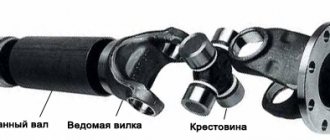
The automatic transmission speed sensor is one of the main elements. Often there are two such sensors, one “reads” the speed of rotation of the primary (input) shaft, while the other transmits to the ECU data on the speed of rotation of the output shaft or differential gear on automatic front-wheel drive cars.
As for the automatic transmission ECU, information from the first sensor allows the controller to determine the degree of load on the internal combustion engine and select the most suitable gear. Readings from the second sensor are needed in order to monitor the operation of the gearbox (how the ECU command is executed, whether the desired gear has been engaged, etc.)
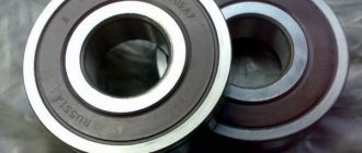
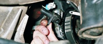
If we talk about the speed sensor and its design, such an element is a well-known Hall sensor. Frequent problems include damage to the housing and problems with contacts. However, it will not be possible to quickly check the speed sensor with a multimeter, so during diagnostics it is recommended to install a known-good element.
Let us also add that on some cars you can also find an inductive speed sensor. The sensor works on the principle that when a gear tooth of the gearbox passes through the magnetic field of the sensor, voltage appears in the coil. This voltage forms a signal and is transmitted to the ECU.
The block takes into account the total number of gear teeth, which allows you to calculate the current speed. It is important to understand that the Hall sensor is visually similar to an inductive one, but the second option is very different in operating principle, it generates an analog signal, does not use a reference voltage, etc. By the way, the inductive sensor can be checked with a multimeter.
- The automatic transmission selector position sensor is necessary for the control unit to “switch on” the appropriate operating mode of the box. In other words, this sensor allows the unit to determine how to operate the hydraulic system, taking into account the position of the automatic transmission selector (PNRD-2-1, manual control M +/-, etc.).
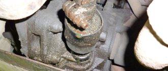
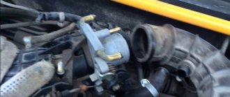
Often the specified sensor is called an automatic transmission inhibitor. This sensor is usually located on the gearbox selector shaft. Also, on some automatic transmissions it can be connected to the mode selection spool valve drive in the valve body itself.
The automatic transmission selector position sensor is also responsible for turning on the reversing lights and controls the operation of the starter drive in the selector positions P and N. If we talk about the device, such sensors may differ, but they are often based on a potentiometer that changes the resistance depending on the position there is a selector.
In a nutshell, the sensor consists of resistive plates and a movable slider directly connected to the selector. Taking into account the position of the slider, the resistance of the sensor also changes, which also leads to a change in the output voltage.
As a rule, over time, this sensor may become unusable or begin to work incorrectly. In some cases, disassembling the closed case and carrying out preventive maintenance helps, but after this further malfunctions are possible. For this reason, experts recommend immediately replacing the automatic transmission selector position sensor.
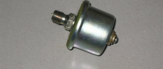
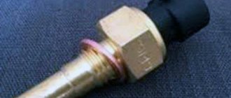
- Temperature and pressure sensors record parameters directly related to ATF. An automatic transmission temperature sensor is necessary because the operation of friction clutches greatly depends on the properties of the working fluid, oil level and temperature.
In simple words, to protect the clutches and gearbox from overheating, a thermistor is installed that can change the resistance when the temperature changes. It turns out that the sensor voltage changes depending on the ATF temperature, and the corresponding signals are transmitted to the ECU.
The automatic transmission temperature sensor is installed in the gearbox housing or integrated into the wiring inside the automatic transmission housing. If, according to sensor readings, the ECU detects significant overheating, the automatic transmission usually goes into emergency mode.
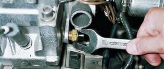
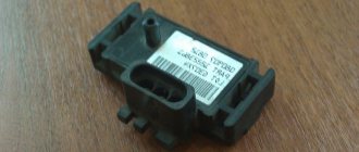
As for the automatic transmission pressure sensor, indicated sensors are usually installed in the valve body channels, measure pressure readings and transmit electrical signals to the automatic transmission electronic control unit.
We also recommend reading an article about how an automatic transmission works and works. From this article you will learn about the design and operating principles of a hydromechanical automatic transmission, as well as the design features of the automatic transmission.
Such sensors can be discrete and analog. The first type registers deviations from certain parameters during automatic transmission operation. Normally, the sensor contacts are closed; if the pressure drops at the location of the sensor, the contacts will be open, the ECU receives a signal and increases the pressure.
An analog sensor takes into account changes in pressure more flexibly by sending different signals. This allows the unit to more accurately make the necessary adjustments, affecting the operation of the automatic transmission.
- In the list of sensors that are used to control the automatic transmission, the electronic control unit of the automatic transmission also receives signals from other ECM sensors. For example, the unit receives signals from the brake pedal sensor to lock the selector when turning on the “parking” mode, the accelerator pedal position sensor (if the gas pedal is electronic), the TPS to determine the current load on the internal combustion engine and select the most suitable gear, etc.
Let's sum it up
As you can see, a group of various sensors and ECUs make it possible to implement dynamic changes in parameters during automatic transmission operation, thereby controlling the operation of the unit, preventing critical loads on the box, etc.
We also recommend reading the article about what an additional automatic transmission radiator is. From this article you will learn why the automatic transmission overheats, and also why it is recommended to improve the cooling of the automatic transmission by installing an automatic transmission add-on radiator.
If the gearbox itself and the control system are in good working order, maximum comfort is achieved when operating a car with an automatic transmission. Gears shift quickly, promptly and smoothly, there are no jerks or jolts during shifts, the gearbox does not slip, etc.
If malfunctions occur in terms of hydraulics, mechanics or electrics, the automatic transmission may go into emergency mode, and an automatic transmission error or “check” lights up on the instrument panel. At the same time, further operation of the car in this case is not recommended, that is, urgent diagnostics of the automatic transmission in a specialized service is necessary.
What are the symptoms of a P0715 code?
The main symptom of a P0715 code is the presence of problems when shifting gears, such as hard or incorrect gear shifting.
The driver can recognize signs of automatic transmission malfunction in three ways:
- Hear: extraneous noises, grinding, crunching while driving.
- Feel: vibrations, loss of dynamics, slipping in all modes, delays when switching, an increase in speed to 3500 - 5000.
- See: oil leak, chips in the pan, abnormal fluid level, errors on the panel.
DSG problems have similar symptoms:
- buzzing and crunching while moving;
- slow acceleration with increasing engine speed;
- clutch slip;
- jolts and jerks when changing gears;
- fluid leak.
Automatic transmission shift sensor | Operating principle, possible breakdowns and their elimination
This is all one mechanism responsible for transmitting information to the gearbox controller about the position of the gearshift lever, displayed on the dashboard, as well as for turning on the reverse lights and controlling the starter drive. Almost all car manufacturers with automatic transmission place it on the selector shaft.
Signs of a broken gear shift sensor
What can cause a sensor to fail? The reason may be abrasion of contacts due to constant use of the lever, or water getting inside due to a leak, especially if the crankcase protection is not installed. If the gear shift sensor fails, the control unit stops receiving information about the position of the selector. There are several signs that the sensor is faulty:
• the “HOLD” light on the dashboard is active, the automatic transmission goes into emergency mode. Turning off the engine and starting it again does not solve the problem.
Read more about what HOLD is in an automatic transmission
• There is only a shift to first speed, there are no other shifts.
• When driving, there are no gear changes, either up (from 2 to 3, from 4) or down (from 4 to 3, from 3 to 2).
This is not a complete list of symptoms of a faulty transmission shift sensor. As already stated, the lack of information causes the car to react differently. The issue can be resolved by computer diagnostics of the automatic transmission. How to replace this sensor?
Sensor replacement technology
We move the selector lever to “N”, remove everything under the hood that may interfere with access: battery, air filter, etc. We disconnect the rod to the gear selection rod and fix it to avoid spontaneous gear shifting.
Article: How to remove and install an automatic transmission
Slightly loosen the rod nut, reducing the fit on the shaft. And now, carefully, with swinging to the sides, we remove the rod from the rod. Disconnect the electrical connector of the sensor. We free the sensor body from extraneous “overlays” that prevent its removal. This could be an oil level dipstick guide, an electrical connector casing, etc., it all depends on the design features of the car. Now use the appropriate heads to unscrew the pin and bolt securing the sensor. Rocking from side to side, remove the automatic transmission gear shift sensor . All. The old one is for disposal, the new one is in its place. Assembly is carried out, as you might guess, in the reverse order.
akpphelp.ru
Removal and disassembly of Selespeed CFC328
It is not difficult to remove the “robot”.
The standard for this type of work is only 1.2 hours. To do this, there is no need to remove the gearbox itself. It is enough to carefully disconnect the electrical wiring and ground, unscrew 10 bolts - and the “robot” is free. The official manual recommends removing it through the bottom of the car (1), as if bypassing the gearbox counterclockwise, but by removing the interfering units, you can pull the entire “robot” (2) assembly up without resorting to a lift (3). Warning: After removing the “robot” block, it is not recommended to touch the gear shift rods on the gearbox (5), and on the mechanical “robot” block you should remember or mark the position of the selection mechanism (4) and gear shift. The default is neutral.
Only in this position of the mechanisms during assembly will the unit work correctly. It can be assembled with other positions of the rods and their corresponding parts, but after such incorrect assembly it is not immediately possible to understand why self-calibration does not occur. In this case, the self-test run by the scan tool ends with error code 00 (Automatic calibration failed).
Diagnosticians begin to sin on everything except incorrect positioning during assembly. In order to make sure that the unit was installed incorrectly, you need to use a diagnostic tool to look at the readings of two position sensors in millimeters (6) - the differences from the tabulated data (7) when a particular gear is engaged should not be more than a millimeter.
Neutral sensor on a manual transmission: types, autostart, installation, adjustment
The neutral sensor on the manual transmission installed in the car will start the engine at the right time with neutral speed and the brake raised. A small device in the gearbox will save you from repeating unnecessary actions.
About autorun
Autostarting the engine in winter is a common and not troublesome task for owners of cars with an automatic transmission. Car alarms provide a special arming algorithm with auto start for vehicles with manual transmission.
Security with start is activated only when the engine is running, and in 30 seconds you need to leave the cabin, close the door and have time to press the remote control button. Otherwise, the car will stall and the engine will not start after a certain time interval, despite the alarm working. When you open the doors again after setting the alarm, the algorithm is also broken and the car will no longer start automatically.
Negative effects of soft neutral
In the alarm settings, especially for cars with a manual transmission, you can select the “Automatic transmission” mode - program neutral. In this case, forgetful and inattentive drivers, out of habit, leave the car at the speed at which they parked. However, many people neglect the handbrake. The alarm starts the engine to warm up. The speed is already set, the handbrake does not work - and an uncontrollable car can lead to unforeseen events and tragedies.
Car owners, after 30 seconds of manipulation with automatic engine start, remember things forgotten in the car. And they are forced to take repeated actions that they took 2 minutes ago. And there are many examples of the fact that a motorist, after “entering” the car again, forgets to turn on the ignition so that the engine starts, and is left the next morning with a frozen engine.
Neutral sensors
Sensors that start the engine come to the rescue when the gear lever is in neutral and the brake handle is raised.
Types of sensors
There are several types of sensors, which will be discussed below.
Reed switch
According to many users, this is one of the best sensors that does not require additional power to operate. A device that opens and closes an electrical network under the influence of a permanent magnet generating an electromagnetic field. The name of the device comes from the merger of two words, since the contacts are sealed in a vacuum glass tube, or in a tube with an inert gas, which prevents a spark from occurring.
The scope of application of the reed switch is wide, despite the fact that it is now being replaced by the Hall sensor, which is simpler in design, but requires an electrical network. Reed switches are used in household meters, security and control systems, in devices related to underwater and water works, in complex medical equipment, and in high-voltage electrical installations.
Divided by:
- closed – the magnetic field opens the circuit;
- switchable - the magnetic field closes and opens the contacts depending on the absence or presence of a magnetic field;
- open – the magnetic field affects the operation of the circuit.
Kinds:
- gas - a glass flask filled with an inert gas;
- mercury - mercury applied to the contact plates improves communication quality, eliminates vibration and reduces resistance.
Disadvantages of using a reed switch:
- short service life.
- contacts become unusable.
- signals arrive at a poor speed, which causes alarms to be triggered once again.
Slit optical device
Using this sensor in a gearbox as a regulator is a reasonable solution. Since the device, consisting of two parts: an emitter and a receiver, connected in the shape of the letter U, is easy to use. The slot in the sensor body is the working area. An opaque object or part that falls into this zone opens the circuit.
The receiver is an LED, photodiode, phototransistors or Darlington transistor. Used in high-speed installations, conveyors, and produced for installation in the ignition key of racing motorcycles. Installing and replacing the sensor does not require much time. May react to dust, gas, water and smoke. This circumstance can lead to serious problems when starting the engine if the lever is in speed.
Inductive non-contact device
Its purpose is to control the position of metal objects or objects. Other materials do not respond to the inductive device. A reliable, high-quality device is used in industries related to the manufacture and production of machinery, transport, and food products. There are cylindrical and box types.
The device consists of:
- a generator that creates an electromagnetic field and interacts with an object;
- a Schmitt trigger that switches different parts of the sensor;
- signal amplifier;
- LED helps monitor switch status and performance;
- compound for protection from external influences;
- housing that protects against mechanical impact. Equipped with fastening parts.
How it works: The generator is the main sensor assembly. The electromagnetic vibrations it causes affect metal objects. When the position of this object changes, the signal changes and the rest of the device reacts. This leads to a short circuit or open circuit. Installed to the manual transmission lever, it will react to the neutral position and signal to the security system that the car can be started.
Hall controller
A sensor on the gearbox protects against auto-starting the engine when the brake lever is in a non-working state and the speed is in any gear. Under the influence of a magnet, a signal is sent to the device, which makes it possible to close or open the network. The compactness and simplicity of the device is used in various fields of industry.
Kinds:
- analog converter;
- digital.
- optic.
How to make a neutral and handbrake adjuster
Craftsmen install sensors that are affordable and of high quality, simplifying the driver’s task. Having started using a reed switch, over time they switch to more modernized and stable types of sensors. The Hall device is in first place in this list, followed by optical, then reed switch, inductive.
The operating principle of neutral sensors is as follows:
- The handbrake is not raised - the alarm blocks the engine from starting.
- The handbrake is raised, the speed lever is in neutral - the controller responds to the brake and speed position. The car alarm blocking is removed. The engine starts.
- The parking brake is raised. Speed lever at any speed. The alarm blocks the engine from starting.
- The LED indicator gives a bright light when the “correct” actions are performed sequentially - brake raised, neutral speed.
- If any sequence is violated, the indicator dims to barely visible light.
- The sensors are installed directly to the gearbox lever. And on the handbrake there is a wire on the alarm.
How to install a reed switch yourself
- The main components of the future engine starting device are a homemade printed circuit board of a suitable size. Reed switch. Magnet.
- Etch with iron chloride along the board marks.
- Solder the reed switch with wires.
- Attach the reed switch board closer to the gearbox lever, which is at neutral speed.
- A magnet is attached opposite the reed switch to activate the neutral sensor, and at other speeds the circuit should open.
- Connect the neutral speed to the security alarm according to the “native” instructions.
- The same response device can be placed on the parking brake wire.
Conclusion
Radio enthusiasts can easily make such a device for cars with a minimum of cost and knowledge. Installing an alarm with a switch to an automatic transmission can one day play a bad joke and start the car at speed and with the brakes down.
Simple manipulations for autostart carried out at the gearbox and on the parking (hand) brake with a neutral sensor will save the car from hypothermia and the driver from frayed nerves.
prodatchik.ru
What does P0715 mean?
Trouble code P0715 is a generic trouble code that indicates there is a problem with the signal between the engine control module (ECM) and the transmission control module (TCM). When this error occurs, the automatic transmission input shaft speed sensor cannot determine the engine speed (torque converter turbine) and sends an erroneous or incorrect signal to the car computer, which does not allow determining the correct gear shift strategy.
Rotation speed sensors for drive (gearbox) control
Application
Drive control sensors take readings of the shaft speed in AT, ASG, DSG and CVT drives. These are indications of the number of revolutions of turbines and drives in AT drives with a hydrodynamic torque converter, the number of revolutions of the primary and secondary pulley in CVT drives, and the speed of both shafts and the drive shaft in DSG drives. If there are high requirements for the dynamics of acceleration control, readings of the engine speed expected at the acceleration element are taken.
To optimize clutch control and prevent the vehicle from rolling back, a sensor may be required to detect the direction of rotation. Both stand-alone sensors and models integrated into electronic modules are used, which are installed both inside the drive and outside.
Requirements
Drive speed sensors are subject to high loads due to
- extreme temperatures from -40 to + 150°C;
- aggressive environment caused by the use of gear oil;
- high mechanical loads with accelerations up to 30g, as well as
- formation of metal particles due to wear of parts in the gearbox.
These loads place high demands on the electronics used in the sensors. With modern oil-resistant housings, gear oil life can reach more than 15 years.
Due to the very compact design of gearboxes, it is usually not possible to standardize the geometric dimensions of the sensors. Thus, each transmission requires special sensor models that vary in length, reading direction and mounting flange in integrated modular types. In stand-alone sensors, another variable is the position of the mounting sleeve and the plug model.
Rice. Sensor models:
- a Bottom reading
- b Lateral reading
- with Oblique reading
- Reading direction
To implement the entire range of functional requirements, Hall ASICs (Application Specific Integrated Circuits) of varying degrees of complexity of data processing algorithms are used.
Rice. Complexity of requirements
If a ferromagnetic trigger wheel or trigger zone (toothed, knurled or stamped) on rotating drive components (transmission) is used to sense RPM, the magnetic field required for the Hall effect sensor to operate is generated by a magnet with a negative bias voltage. It is located in the sensor just behind the application specific integrated circuit.
Compact transmission models increasingly require the ability to read speed readings over long distances (magnetic air gaps) through rotating non-magnetic components or the housing wall. For such operating conditions, multipole rings (magnetic rings) are used; the sensor does not use a magnet with a negative bias voltage.
Design
Rice. Hall sensor with two-wire interface
Special Hall integrated circuits used in drive speed sensors, depending on the magnetic interface, are fixed in a holder in the presence of a magnet with or without a negative bias voltage, electrical contact is created by welding, then the chips are installed in the housing, filled with epoxy resin or - in models , which are installed outside the drive (gearbox) - are installed in an oil-impermeable shell by coating with a seamless shell on the extruder. The sensor has a two-wire interface that combines optimal diagnostic capabilities with a minimum number of electrical connections. Two connectors serve both for power supply of Hall integrated circuits and for signal transmission.
Automatic transmission selector
The gear lever is a unique way of communication between the driver and the car. With each new car model, it is becoming more and more improved and, in addition to the main handle, it is slowly acquiring additional buttons and indicators.
The location of the lever differs depending on the machine model. In modern cars, it is common to have a steering column arrangement in the center of the dashboard (if the driver’s seating position is high, then on the console).
To prevent accidental switching between modes, there is a button on the selector. It is located on the side, top or front. Until it is pressed, the range of the lever cannot be changed. The stepped selector slot also prevents unnecessary range changes.
In the steering column version, the lever can be moved after the driver pulls it towards himself.
Causes
The most common causes of the P0715 code are:
- Malfunction of the automatic transmission input shaft speed sensor
- Damage to sensor wires
- Poor electrical connection in the sensor circuit
- Faulty shift solenoid valves
- Damage to the gearbox valve housing
- Low or contaminated transmission fluid
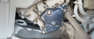
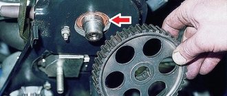
Failure of the gear selector position device can be caused by simple high humidity. That's how it happened for me.
After I opened this device with a screwdriver, I found oxidized contacts, dirty internal surfaces and dried grease. There was no point in repairing it for me, so I replaced it with a new one.
Moisture enters due to loss of tightness. To prevent water from getting in, it is necessary to install the crankcase on the bottom of the car, which protects the selector shaft, automatic transmission ECU and engine from dust, water and dirt. It also protects these devices from impacts that may occur while driving on uneven dirt roads.
In addition to water, a malfunction can occur due to contact abrasion. Erasing occurs if there is constant operation of the selector lever, especially in traffic jams.
A short circuit can also cause the device to fail. Incorrect adjustment of the selector lever, damage to the gearbox valve body are also causes of device malfunctions.
It is possible to determine the reason why the automatic transmission does not work only after collecting the main signs and deciphering the error codes. The following are examples of typical automatic transmission faults, which, if ignored, can lead to an accident.
Lever link
The selector link is the connecting mechanism between the gear lever and the automatic transmission. The unit fails due to lack of lubrication, dirt, or mechanical failure. Incorrect operation of the mechanism may be due to misadjustment.
The main symptom of a malfunctioning link is difficult switching of transmission operating modes. If you do not move the selector to the lower stages for a long time, then over time the rubber bands will dry out and the lever will become covered with corrosion.
The appearance of play when the selector moves left and right can cause accidents, as it interferes with clear gear shifting. The automatic transmission lever dangles most often due to misadjustment or loosening of the cable bracket connection.
Read more: External signs of a timing belt failure
Oil leak
A drop in ATF level can cause a breakdown of the entire automatic transmission, as the unit begins to run dry. Lack of pressure leads to clutch slipping and incorrect gear shifting. Jerking, jerking, and slipping appear. Possible error codes are P070A - P070F.
Oil leakage occurs due to the following problems:
- wear of oil seals, gaskets, O-rings;
- loose drain plug;
- a wet spot at the junction of the internal combustion engine and automatic transmission indicates wear of the oil pump bushing or a crack in the torque converter;
- bottom breakdowns.
Control block
A faulty automatic transmission control module puts the box into emergency mode: when the engine is running, the modes switch incorrectly or do not respond at all to the movement of the selector. The electronics generate errors U0101, P0700 - P0702 and stop working for the following reasons:
- there has been a power surge;
- contacts have oxidized;
- cables are damaged;
- an electronic component has broken down;
- the box has overheated;
- Water has entered the module.
Signs of a faulty automatic transmission valve body: shocks and jolts when shifting gears, slipping when hot. In advanced cases, oil starvation, overheating, and deterioration in vehicle dynamics may occur. Possible error codes are P0700 - P0702, P0729 - P0736, and other errors indicating problems with the solenoids.
Malfunctions and errors in the automatic transmission valve body appear due to old oil and high loads:
- the hydraulic plate channels become dirty;
- the solenoid channels become clogged;
- the geometry of the separator plate changes;
- valve body valves get stuck;
- seals wear out;
- Wiring burns out.
Clutch basket
The clutch in the robot “turns off” the torque so that the gearbox safely changes gear. A common problem with the unit is slipping. This could mean that:
- the driving or driven clutch disc is worn out;
- the clutch “burned out” due to sudden starts and prolonged overloads;
- the damper springs of the driven disk have weakened;
- The friction linings have delaminated.
If while driving the car goes into emergency mode and there is no movement either forward or backward, you need to check the release bearing and its guide. A part broken due to high loads leads to breakage of the entire basket, “gnawing” the pressure petals. You can understand that the automatic transmission is dying by shifting the lever: at first it will be difficult to engage a certain gear, and when the transmission dies, it will be impossible.
A crunching sound when engaging forward or reverse gear indicates that the clutch is not fully engaged. The problem may be hidden in the actuator, release bearing or deformed clutch disc. Possible error code is P0810 - P0813.
A malfunction of the automatic transmission torque converter manifests itself in the form of knocking, rustling, vibrations, poor dynamics, and increased fuel consumption. The car will move with difficulty and pick up speed slowly. If the unit is completely out of order, the car will stall or will not budge. Possible error codes are P0740 - P0744.
The automatic transmission fluid coupling does not work and displays errors for the following reasons:
- the plain bearings are worn out;
- the wheel hub fell apart;
- seals are destroyed;
- the friction clutch of the locking clutch is worn out;
- case neck broken;
- wheel blades are destroyed.
“Donut” is the main pollutant and heater of automatic transmission oil. Deterioration of the properties of the liquid leads to a drop in pressure and overheating of the box. The liquid can heat up to 120 - 150℃, “burning” the machine parts. To reduce the load on the torque converter, additional ATF cooling radiators are installed.
Brake clutch
The brake clutch smoothly fixes the planetary mechanism of the machine. Wear of the brake band causes jolts, jerks and other troubles when shifting gears. If the car slips in place, or one of the gears does not work, the brake band piston cuffs may have broken.
The brake clutch does not work in automatic transmissions, usually with high mileage; in simple boxes, such as Toyota A131L, VW 010, Chrysler 31TH, the band is replaced in a completely worn out state. By this time, the clutch is completely saturated with burnt oil and adhesive resins from the “eaten” clutches.
Basics of proper inspection of an automatic transmission
Before making a decision to repair an automatic transmission, the technicians collect the history of the “patient” and remove error codes for automatic transmission faults. You can diagnose an automatic transmission using the ELM327 scanner. To make a diagnosis yourself, you will have to study the device and the characteristic breakdowns of your box, and stock up on manuals.
Error codes help to find the problem area, but this method does not give accurate results. Further further research is carried out:
- check the operation of the automatic transmission “cold”, “hot”, in different modes;
- check the fluid level;
- change dirty oil and filter;
- inspect the pallet for the presence of chips, large metal particles and plastic debris;
- check the voltage in electrical circuits.
Read more: Renault Logan 2020 2017 in a new body equipment and prices photos technical specifications video test drive
If the problem is not identified, the automatic transmission is disassembled for inspection and testing:
- check the integrity of friction discs, brakes, bushings, bearings;
- check the pressure in the valve body channels;
- measure the resistance of the solenoids;
- measure gaps on bushings, washers, and clutch packs;
- disassemble the torque converter.