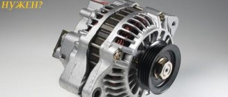
What is a three-level voltage regulator and what is it for? This is a device that automatically maintains alternating current voltage at the vehicle's alternator terminals. It is located in the side panel. This device is needed to allow the car battery to charge normally.
The three-level unit itself is installed on board the car, and its panel or brush-type unit (depending on the modification of the device) is installed directly into the generator. The voltage levels it regulates are switched using a three-position toggle switch built into the generator generator, depending on the following conditions:
Minimum - voltage level no more than 13.6 Volts. It is installed when the car is operated at air temperatures from minus twenty to plus twenty, for example, during long climbs.
Normal is a voltage level of no more than 14.2 Volts. Installed when the vehicle is operated at air temperatures from zero to plus twenty degrees Celsius.
Maximum - voltage level 14.7 Volts. It is necessary to install when the car is operated at sub-zero temperatures, after the car has been idle for a long time, and also if additional electricity consumers are turned on or the battery has been significantly discharged when connecting a TV, refrigerator and car radio.
The use by the owner of a vehicle of such a device as a three-level voltage regulator makes it possible not only to completely solve all problems with it, but also to significantly increase its service life.
A standard voltage regulator built directly into the generator, which has negative thermal compensation, is simply not able to control the ambient temperature outside the generator, so the air temperature inside the generator itself can sometimes exceed 100ºC. Here it is also worth mentioning the fact that when additional loads are turned on, namely headlights, stove, glass heaters, etc., the battery may discharge even with a working standard voltage regulator and a running engine.
In order to save the driver from such unpleasant situations, a three-level voltage regulator was developed. This device has proven its reliability and, of course, efficiency many times. All products from companies that produce such devices provide a company guarantee from the date of sale. The three-level voltage regulator for automobile vehicles is packaged by the manufacturer in personal branded packaging and has detailed installation and operating instructions. or rather, even a beginner can install such an irreplaceable device as a three-level voltage regulator - there is no need for special knowledge or equipment. A three-level voltage regulator is used as an alternative to the standard one.
Three-level voltage regulators are an assembly of semiconductor elements that change the voltage on the excitation windings of the generator. At different loads on the on-board electrical network, the generator produces current with different characteristics. Voltage regulators are quite useful devices: at a low price, they increase the service life of the battery and prevent the occurrence of emergency situations associated with its discharge.
Operating principle of the voltage regulator
The voltage of a generator without a regulator depends on the rotation speed of its rotor, the magnetic flux created by the field winding, and, consequently, on the current strength in this winding and the amount of current supplied by the generator to consumers.
The higher the rotation speed and the excitation current, the greater the generator voltage; the greater the current of its load, the lower this voltage. The function of the voltage regulator is to stabilize the voltage when the rotation speed and load changes by influencing the excitation current. Electronic regulators change the excitation current by turning on and off the excitation winding from the supply network, while changing the relative duration of the on-time of the excitation winding. If to stabilize the voltage it is necessary to reduce the excitation current, the switching time of the excitation winding is reduced; if it is necessary to increase it, it is increased.
It is convenient to demonstrate the operating principle of the electronic regulator using a fairly simple diagram of an EE 14V3 type regulator from Bosch, shown in Fig. 5.6:
The voltage sensor is a zener diode VD2. When the specified voltage value is reached, the zener diode “breaks through” and current begins to flow through it. The voltage is supplied to the zener diode VD2 from the output of the generator “D+” through a voltage divider on resistors R1 (R3 and diode VD1, which performs temperature compensation. When the voltage is low, the zener diode does not pass electric current and through the bulb HL the current passes to the excitation winding of the generator. When the voltage reaches its maximum value , the zener diode breaks through and the electronic unit stops supplying current to the excitation winding (Fig. 5.7).
From Fig. 5.6 clearly shows the role of the HL lamp for monitoring the operating condition of the generator set (charge monitoring lamp on the car’s instrument panel). When the car engine is not running, closing the contacts of the ignition switch SA allows current from the battery GA to flow through this lamp into the excitation winding of the generator. This ensures the initial excitation of the generator. At the same time, the lamp lights up, signaling that there is no break in the excitation winding circuit. After starting the engine, almost the same voltage appears at the generator terminals “D+” and “B+” and the lamp goes out. If the generator does not develop voltage while the car engine is running, the HL lamp continues to light in this mode, which is a signal of a generator failure or a broken drive belt. The introduction of resistor R into the generator set helps to expand the diagnostic capabilities of the HL lamp. If this resistor is present, in the event of an open circuit in the field winding while the car engine is running, the HL lamp lights up.
Currently, more and more companies are switching to the production of generator sets without an additional excitation winding rectifier. In this case, the generator phase output is fed into the regulator. When the car engine is not running, there is no voltage at the generator phase output and the voltage regulator in this case goes into a mode that prevents the battery from discharging to the excitation winding. For example, when the ignition switch is turned on, the regulator circuit switches its output transistor into an oscillatory mode, in which the current in the field winding is small and amounts to fractions of an ampere. After starting the engine, the signal from the generator phase output switches the regulator circuit to normal operation. In this case, the regulator circuit also controls the lamp for monitoring the operating condition of the generator set.
Checking the generator voltage regulator
may be necessary when problems with the battery begin to occur. In particular, it began to recharge. When such a malfunction occurs, it’s time to check the generator voltage regulator relay.
The task of this simple device is to regulate the voltage of the electric current to the battery. When it fails, the battery is either not charged enough or, on the contrary, overcharged, which is also dangerous, since this significantly reduces the battery life.
Agree that this prospect is not very good because of one small detail.
This is why it is so important to monitor the operating condition of the voltage regulator (it can also be called a pill or a chocolate bar). But in order to properly check the voltage regulator, you need to know its type and several important features.
Characteristics of the voltage regulator
What is a DC regulator, what role does it play in a car alternator, what voltage should the alternator produce? Is it possible to raise and increase the number of output parameters using a simple three-level device? First, let's look at what the design of the element is and what its purpose is.
Purpose
So, what is an electronic car generator voltage regulator used for? When starting a power unit, as is known, the crankshaft begins to rotate first; this occurs as a result of the influence of direct current on it. The current in amperes initiates the movement of the rotor mechanism, after which the generator unit begins to function. A constant voltage regulator is used to control all processes.
If the voltage is not high, and due to the failure of the generator voltage regulator there is no power to the mechanism, the unit will not be able to start. If there is no generator power, the current in amperes will simply not be supplied to the equipment. A simple voltage regulator makes it possible to keep the current in amperes in the specified range; this is its main purpose.
Design
Now let’s look at the issue of the device: any increasing pH, even simple and homemade, will consist of:
- Rectifier block. This element includes several diode components, usually their number is six. All components of this block are connected to each other via a special bridge.
- Rotary mechanism with winding. This device rotates around an axis; its purpose is to generate a magnetic field inside the unit.
- Stator mechanism. On the body of this device there are three windings connected to each other. Thanks to these windings, it is possible not only to provide a higher charge, but also to increase power for the car battery. They also make it possible to supply current to the entire electrical network of the vehicle.
- Impellers. This element is installed on the outer part of the mechanism. The impeller is used to blow and cool the winding; without it, the latter may overheat.
- Case cover. Its purpose is to hide all the constituent structural parts of the unit, thereby ensuring reliable protection of the device from dirt and dust. Depending on the model, the lid may have a special casing - if the design implies its presence, then the regulatory element will be located immediately behind it.
- And the relay itself. If the generator produces a high voltage that is not typical for the on-board network, or is too low, then the relay will stabilize this parameter to the desired level. The stabilizer must provide exactly the optimal voltage, not increased or decreased (video author - Vitaly Galankin).
Principle of operation
If you decide to connect a winding without a regulator to a power source, then the DC value after connection will, of course, be increased. Using this device, the value is equalized, which helps prevent equipment breakdown. The control device of an asynchronous generator unit is, in fact, a switch. If the voltage at the generator terminals is not normal, the mechanism adjusts the parameter to the desired value.
Checking the relay regulator
How to check the fuel pump with your own hands
It is recommended to check the relay regulator on a special stand. In this case, the relay-regulator must be cooled to ambient temperature and installed on the stand in the operating position (vertical position with terminals to the right). The relay regulator can also be checked directly on the car. To do this, you must have the following instruments: a DC voltmeter with a scale of up to 20 V with a division value of 0.1-0.2 V and a DC ammeter with a scale of 20-0-20 A with a division value of 1 A.
Checking the reverse current relay
The reverse current relay is checked with battery 4 connected (Fig. a).
To do this, you need to disconnect the wire from terminal B of the relay-regulator and connect ammeter 5 between this wire and terminal B of relay-regulator 1 using an additional conductor. Voltmeter 2 must be connected between terminal I and the ground of the relay-regulator.
By slowly increasing the number of revolutions of the generator armature, the voltage at which the relay contacts closes is determined. The relay switching voltage should be in the range of 12.2-13.2 V.
Rice. Diagram of connection of devices for testing the relay-regulator: a - diagram of connection of devices for testing the reverse current relay, b - diagram of connection of devices for testing the voltage regulator and current limiter; 1 - relay regulator; 2 - voltmeter; 3 - generator; 4 - battery; 5 - ammeter; 6 - rheostat
The moment of closure is easy to notice by the deflection of the ammeter needle. Then, by reducing the number of revolutions of the generator 3 armature, it is necessary to determine the amount of reverse current at which the relay contacts open. The reverse current should be in the range of 0.5-6 A.
If, when the generator armature speed increases, the increase in voltmeter readings stops and the relay does not turn on (the ammeter needle does not deviate, the relay contacts do not close), you must first check and adjust the value of the regulated voltage, and then the value of the relay turn-on voltage.
Checking the voltage regulator
The circuit diagram for connecting devices for testing the voltage regulator is the same as for testing the reverse current relay. It is only necessary to disconnect the battery (in a car, the battery is disconnected after starting the engine, for stable operation of which it is necessary to maintain the speed of the generator armature above the speed of turning on the reverse current relay) and connect voltmeter 2 between ground and terminal B of the relay-regulator (Fig. b) . The generator armature is rotated at a speed of 3500 rpm. Consumers or rheostat 6 are connected to terminal B of relay-regulator 1 so that the generator load is 10 A (measured according to the ammeter readings).
If the regulator is working properly, the voltmeter should show a voltage of 13.8-14.8 V.
Checking the current limiter
When checking the current limiter, the device switching circuit remains the same as when checking the voltage regulator (Fig. b). The generator armature is rotated at a speed of 3500 rpm. Then gradually increase the generator load with a load rheostat and observe the ammeter needle. The ammeter readings at the moment when, despite the decrease in the resistance of the rheostat, the needle stops, correspond to the value of the maximum regulated current.
Types of relay regulator
For any car, including VAZ, you can buy RRNG of various types. And although semiconductor models have become especially popular lately, we will look at all existing ones.
- Two-level - despite the fact that this type of relay is considered obsolete, many motorists continue to use it. The “foundation” of such devices is an electromagnet connected to the sensor by a winding. The springs perform the function of a setting device, and a small movable lever acts as a comparison device, which carries out the switching. The constant resistance is the control unit, the contact group is the actuator. The main disadvantage of two-level sensors is their short service life, as both car enthusiasts and experts say.
- Electronic - as you probably already understood, they are also called semiconductor. These are more advanced and durable devices, we have already talked about them earlier.
- Three-level regulator - the design of the mechanism is not much different from those described above, only in that there are several additional resistances.
- Multi-level - mechanisms equipped with 3, 4 and even 5 additional resistances; there are options that can operate in tracking mode. Such models are one of the latest creations of developers, hence the slightly corresponding price.
On average, a semiconductor relay-regulator will cost you at least 300-400 rubles. And my advice to you is to buy two at once, let it be in reserve, because this is one of those parts that will not interfere with the driver on the road.
AUTO ELECTRICIAN - Checking the relay
Relay test
Making your own battery charge indicator controller
Many electrical circuits contain relays. If a consumer is turned on manually, the relay is ordered to supply power to the consumer. You can supply power to the consumer directly from the battery. When significant current consumption occurs, a relay is switched into the circuit so as not to overload the switch. In addition to the switch relay, there are also functional relays, such as the windshield washer relay.
Checking the turn-on relay
When the corresponding consumer is turned on, a signal is sent to the relay. In this case, the electric control current, acting on the electromagnetic coil, closes the operating current circuit, providing power to the consumer.
The easiest way to check the functionality of the relay is to replace it with another, working one. For example, they go to a service station. If there is no spare relay, it is recommended to check as follows. The terminal designations below may differ from those shown.
1. Remove the relay from the holder.2. Turn on the ignition and the corresponding switch.3. Using a voltage tester, check if there is voltage at terminal 30(+) of the relay holder
To do this, connect the device to ground (-), and carefully insert the other tip of the device into terminal 30. If the device LED lights up, there is voltage
If the device shows no voltage, check the diagram to see if there is a break in the path from the positive pole (+) of the battery to terminal 30.4. Prepare a jumper from insulated wire with stripped ends.5. Connect a jumper between terminal 30 in the relay holder (+ battery, always supplies voltage) with the output of the relay NO contact (terminal 37). This simulates the operation of a working relay. Where the terminals are located in the relay holder is indicated on the relay.6. If the consumer operates when the jumper is on, we can conclude that the relay is faulty.7. If the consumer does not work, find out whether the ground connection to the consumer is OK. Then check the connection from terminal 87 to the consumer. If there is a break, fix the problem.8. If necessary, insert a new relay.
| If the malfunction appears intermittently, the cause is usually the relay. In this case, sticking of contacts may occur. In this case, lightly tap the relay body with your finger. If the relay operates, replace it. |
Video. Generator in a car
Do-it-yourself flashing brake light in a car
The voltage regulator occupies one of the key places in the car circuit. It is necessary to constantly monitor the condition of the device, carry out scheduled inspections in a timely manner, and clean the contacts (to prevent malfunctions). Because The part is located on the lower side of the engine compartment, not protected from dust and moisture; regularly clean the surfaces from dirt.
If there are external defects or damage, you should not use such devices, because in this case, a rapid discharge of the battery or complete failure of the car generator, as well as the electrical part of the car (due to a sharp increase in voltage in the on-board network), is possible.
The regulators maintain the generator voltage within certain limits for optimal operation of electrical appliances included in the vehicle's on-board network. All voltage regulators have measuring elements, which are voltage sensors, and actuators that regulate it.
Modern cars use semiconductor contactless electronic regulators, which, as a rule, are built into the generator and combined with the brush assembly. They change the excitation current by changing the time the rotor winding is switched on to the supply network. These regulators are not subject to misadjustment and do not require any maintenance other than monitoring the reliability of the contacts.
Voltage regulators have the property of thermal compensation - changing the voltage supplied to the battery, depending on the air temperature in the engine compartment for optimal battery charging. The lower the air temperature, the greater the voltage must be supplied to the battery and vice versa. The thermal compensation value reaches up to 0.01 V per 1°C.
Car alternator output voltage problem
The list of functions of the generator necessarily includes recharging the on-board battery, which is carried out with a certain current to ensure a long service life. The simplest way to set its value is to slightly exceed the voltage taken from the output of the relay-regulator over the current value of the battery voltage. In this case, a serious problem immediately arises, which is due to the fact that, depending on the ambient temperature, the value of this excess should be different.
An obvious and fairly easily implemented solution to obtain a given output voltage using temperature correction of the regulator response threshold by installing an appropriate sensor is of low efficiency. The reason for this is that the temperature in the engine compartment, due to its proximity to a heated engine, differs from the air temperature, and it is not possible to determine the degree of this difference by simple means.
Another problem in determining the set value of the charging current is due to the fact that even at a constant ambient temperature, the load on the on-board network varies within wide limits. This leads to a “failure” in the battery charge level and difficulty starting a cooled engine after parking.
A good way to solve these problems is to switch to a relay-regulator, which makes the necessary adjustments by discretely changing the voltage that the generator creates. The specified value of the response threshold of this device is set by the driver independently using a three-position toggle switch. Some regulators connect automatically and contain an internal sensor that monitors the instantaneous value of the on-board network voltage. In both cases, the selection of the cutoff threshold is carried out taking into account external factors, primarily the current temperature and operating conditions of the vehicle.
How to check a relay in a car
For many car owners, the relay turns out to be a very incomprehensible thing. Its malfunction may affect the failure of various equipment, so you need to know how to check the functionality of the relay.
To understand the operating principle of this device, it is worth reading the very detailed article How relays work in a car. In short: there is a small electromagnet installed inside the relay housing. When voltage is applied to its contacts, it attracts the jumper, and it closes the contacts of the power line - the equipment turns on. Based on this, there are certain relay malfunctions that can lead to its failure.
When troubleshooting any equipment connected via a relay, you need to check whether it is working. In modern cars, relays are installed in mounting blocks, so it will be based on this. If you have a “free-standing” relay, the testing principles are the same.
Checking the presence of power at the control contacts
When certain conditions occur that are necessary to turn on the equipment powered through the relay (for example, turning on the headlights from the interior), the relay should click. If there is a click, then we immediately move on to the next section of the article about power contacts. If there is no click, you need to check the presence of voltage at the control contacts. You can determine the presence of voltage with a regular test light or a multimeter. Moreover, the multimeter is able to show low voltage, which the light bulb “will not notice.”
To measure the voltage at the relay contact, in some cases it is enough to slightly pull it out of the mounting block socket and touch the probe of a test lamp or multimeter to one of the control contacts. The second dipstick, accordingly, needs to be leaned against the metal of the body. However, it is safer and easier to pull out the relay completely and insert the probe into the desired socket of the block.
If there is no voltage at any control contact, it means that the relay will not turn on and most likely it is not to blame for the equipment failure. You need to look for the reason why current does not flow to the relay.
In order for the magnet located inside the relay to work, in addition to the “plus”, there must also be a “ground”, that is, a connection to the body. You can check its presence using the same “control”. Place one lamp probe on the positive terminal of the battery, and the second in the “mass” socket of the mounting block. Just do not connect these places with a regular wire - this will lead to a short circuit! A light bulb or multimeter will eliminate this danger and show whether there is a mass connection in the corresponding socket.
We check the presence of voltage at the power contacts of the relay
If the relay clicks, it means that the control electrical circuit is working, the magnet is activated and the jumper moves. In this case, you need to check the presence of voltage at the power contacts of the relay. There is always voltage on one contact, and on the second it should appear when the relay is turned on. With the equipment connected through the relay being tested turned off, locate the power contact that is energized. To do this, insert the test lamp or multimeter probe into the corresponding socket of the mounting block, and the other end into the car body.
If there is no voltage at any power contact, it means that the power line is faulty and the relay has nothing to do with it either. The reasons for power line failure can be different, but first you should check the fuse. If there is voltage at one of the power contacts of the relay, then when the relay is turned on (the relay clicked, there is voltage at the control contacts), there should be voltage at the second power contact.
If the relay is turned on, and there is voltage on only one power contact, it means that current does not pass through the relay contact group. This usually happens due to burnt contacts of the jumper that closes the power line. It is easier to replace such a relay with a new one, since disassembling this structure and trying to clean the jumper is a rather difficult and unreliable task. Moreover, the cost of most relays is low.
Checking the functionality of the regulator
On almost all car models, the regulator relay is diagnosed in the same way. To carry out diagnostics, you need a constant voltage source (battery, batteries), a 12 V lamp or a voltmeter.
The minus contact is connected to the device plate, the plus contact is connected to the regulator relay connector.
After removing the regulator from the body, it is necessary to check the functionality of the brushes. If they are less than 5mm in length, then the brush assembly must be replaced.
An incandescent lamp must be included in the circuit between a pair of brushes:
- the extinguishing of the light bulb as the voltage increases indicates the serviceability of the device;
- Constant lighting of the light when changing parameters indicates a malfunction of the voltage regulator.
Soldering new brushes will not bring results, because... the reliability of the design will be significantly reduced. It is unacceptable to use LED products for testing, because Carrying out diagnostics according to this scheme will not give real results.
Test without stress relief
It consists of measuring the on-board voltage in the car. The presence of surges in the network is also determined by the blinking of the lamps during the trip. To check, you will need a multimeter (or a regular incandescent lamp). A multimeter allows you to get more accurate results.
Procedure:
- Start the engine, turn on the headlights.
- Connect the measuring device to the battery.
- The operating voltage ranges from 12 to 14.8 V. If the voltage regulator goes beyond this range, it is considered faulty.
Testing under voltage does not determine the condition of the brush assembly. Exceeding the operating voltage parameters may be associated with weakening or oxidation of contacts.
The operation of control systems in cars is being improved. For modern cars there is no point in using two-level regulation. More advanced systems have 2 or more additional resistances. In new models, instead of the traditional additional resistance, the principle of increasing the frequency of operation of the electronic key is used.
Along with the classical ones, automatic servo control systems are used, in which there is no electromagnetic relay.
The most common method is a three-level frequency modulation control circuit to control logic elements.
Checking the combined relay-regulator
If the brush assembly is combined with the relay, the generator will need to be removed for inspection. First, you need to check the combined relay-regulator circuit, which is used today on many foreign cars and even domestic cars.
To do this, you will need to remove and disassemble the generator, since the unit we need is attached to the generator shaft along which the brushes run. We look for a “window” for the brushes on the generator, unscrew the fastening bolt, remove the brush assembly and clean it. It's usually covered in graphite dust.
Now we need to build a custom circuit using a power supply with a regulated load. We also need a battery, because the power supply or charger will not work without it. So, we connect the charger to the battery and in parallel to the relay-regulator, and to the latter we also connect a 12 V light bulb.
With this connection, the light bulb will light up - this is normal, since the brush assembly is a conductor, and in a quiet state the voltage here is 12.7 V. Now we need to raise the voltage on the charger to 14.5 V. The lamp should go out when this indicator is reached. After all, 14.5 V is the “cutoff” for voltage growth. And if the lamp goes out, it means that the relay has worked, and in principle it is working.
Otherwise, if the voltage reaches 15-16 V and the light is on, it means that the relay does not cut off. In this case, it must be replaced with a new one.
Now you know how to check the relay regulator with a multimeter, and you can do it yourself.
A relay is a separate device (as opposed to integrated circuits) used to control high power signals with low power signals. The relay separates and protects the low voltage circuit from the high voltage circuit by means of an electromagnetic coil. This article will tell you how to test both the relay (solid state) and the coil.
How to test the generator regulator relay. Do it yourself, using a multimeter. Very simple
Problems of “undercharging”, as well as “overcharging” of the battery in principle, can be caused by many reasons, but the very first and most common on many cars (our VAZs are no exception here), as well as on many motorcycles, is the output of the generator relay-regulator from building. This device, despite its compactness, will protect your battery and make its service life much longer. However, if they fail, it can simply kill the battery in a matter of weeks, so if you see white streaks, and also, the engine does not start after night, even the starter does not “turn” - it’s time to check the relay regulator of your car, and here’s how it works do it yourself, and today I’ll tell you in detail...
THE CONTENT OF THE ARTICLE
To begin with, the definition
A relay regulator is a device that regulates the current from the car's generator, preventing the battery from overcharging, protecting it from overcharging, which is detrimental to the battery. Thus, this device greatly extends the battery life.
Essentially, this is just a voltage stabilizer that prevents the voltage from the generator from exceeding the threshold of 14.5 Volts; it is a very accurate device and is required for all types of cars. However, it can be distinguished into two types.
Types of relay-regulator
To exaggerate, there are only two types, but each works on the same principle, namely, “cuts” or increases the voltage to the desired level.
- Combined with brush assembly. Usually it is mounted on the generator itself, in the housing where the brushes are located, there is also a relay regulator.
- Separate. Usually it is mounted on the car body, the wires go from the generator to it, and only then to the battery.
The housings are non-separable and tight and of a different type (often filled with sealants or special adhesives), that is, they cannot be repaired. To be honest, they are quite cheap, especially for our VAZs, so it’s easier to buy a new one than to tinker with an old one.
These are the most common types, of course, previously there were so-called ones combined with terminals, but they didn’t catch on because the device is not very convenient, so I won’t talk about them.
If your relay is “broken” and is constantly recharging, then it’s worth changing it, but first you need to make sure that this is the problem. Now there are only two ways to check: - without removing it on the car itself, and checking an already removed relay. Let's look at both options.
How to check the relay - regulator without removing it from the car?
Indirect signs
If your “regulator” is out of order, you will notice it very quickly, especially if it is winter and frost outside. The fact is that there will be either an “undercharge” or an overcharge of the battery. If the charge is under-charged, you simply won’t start your car - you come to the parking lot, insert the key, and the car barely turns the engine, or doesn’t start at all, sometimes even the lights go out.
When recharging, almost the same thing will happen, only the reason will be boiling away of the electrolyte from the battery cans. It can be indirectly determined by the rapid decrease in electrolyte in the banks, and a white coating on the top of the battery, as well as on parts of the body underneath it. It’s worth thinking about it and checking the regulator relay.
However, this is not our method, we need to make sure more precisely.
Correct Method
To do this, we will use our voltmeter; we need to measure the voltage at the battery terminals with the engine running. To begin with, I would like to note that when the engine is not running, the normal voltage should be within 12.7V, perhaps a little less, but if you already have 12V, then the battery needs to be recharged! Or look for reasons for undercharging.
SO:
- Start the engine
- We set the multimeter to a value of up to 20 Volts
- Connecting the probes to the terminals
- If the voltage is approximately 13.2 - 14V, this is normal.
- We increase the speed (say to 2000 - 2500), the voltage will begin to increase, from about 13.6 to 14.2 V, this is also normal.
- Next, we try at maximum speed (more than 3500), the voltage should be from 14 to 14.5V, but no more!
If you have deviations, up or down, namely at any speed the voltage remains at 12.7V, or even drops to 12V, then this indicates a malfunction of the relay regulator.
Also, if the voltage is higher than 14.5V, for example - 15 - 16V, again the relay regulator is faulty and needs to be replaced.
To be completely honest, it is not always the relay that indicates a malfunction; often the generator itself fails. If the “regulator” is located separately, then you need to change it first; if nothing has changed, remove the generator and completely check the system. If the brush assembly is combined with the relay, then the generator must be removed!
Checking the combined relay-regulator of the car
First we will check the combined relay-regulator circuit together with the brush assembly. These are now installed on many foreign cars, and by the way, on many domestic cars (often labeled Y212A).
As you understand, it is necessary to remove the generator and disassemble it, since this combined unit is attached at the back next to the generator shaft, along which these brushes run. For this:
- We look for a special “window” on the back of the generator where the brushes are immersed.
- Unscrew the fastening bolt.
- Remove the brush assembly.
- We clean it - as a rule, it will be covered in graphite dust; the brushes are made of graphite, using special carbon.
Then we need to check it, but for this we assemble a certain circuit, it is advisable to use a power supply with an adjustable load or a charger. We also need to take a regular 12V light bulb from a car, for example from a “dimensions”, we will need wires to assemble the entire system.
We may need a battery, because many chargers do not work without it. But from the wire from the battery we connect the relay-regulator, to the brushes of which we connect a 12V light bulb, this can be done with small alligator clips, the main thing is not to break the graphite elements. A small diagram for understanding.
If you connect everything in a calm state, the light will simply light up and stay lit, this is normal, since the brush assembly is a conductor of electricity from the shaft. Let me remind you that in a calm state, the voltage on the brushes will be approximately 12.7V.
Now we need to raise the voltage on the charger to 14.5 V, the lamp will light, but when this threshold is reached it should go out! That is, 14.5 V is a kind of “cutoff” for a further increase in voltage! If you lower the value, the lamp should light up again. Then your relay-regulator is working, it passed the test.
If the voltage reaches 15 - 16V and the light is on, this means the relay has failed and needs to be replaced! It does not cause a “cut-off” and will help recharge the battery. Here's a simple check. Now a short video on the topic.
Testing an Individual Relay
Similarly, you can check a new type of regulator, that is, a separate one, here the verification process is much easier. For example, let’s take a model like Y112B; they were installed on many domestic cars before (VAZ).
This is a separate element, so we simply unscrew it from the body (sometimes from the generator cover) and attach it to our stand. Once again, I would like to remind you that it is advisable to have a 12V power supply, then the testing process will be much easier. If not, we use a charger (with adjustment modes) and connect it according to the lower diagram.
The check is the same, we increase the voltage to 14.5 V, the lamp should go out, if not, or turns off at a voltage much higher, then the relay has failed and needs to be replaced.
Old type or check 591.3702-01
This is a very old type of relay; it was installed on “penny” cars, as well as on many rear-wheel drive cars. It has also always been separately mounted on the body, but the check here is slightly different in terms of contacts.
If you take their markings, then there are only two of them - “67” and “15”. The first contact “67” is a minus, as is the relay body itself, but “15” is a plus. The principle of operation is the same, we connect our charger - we start checking, increase the voltage to 14.5V, then look at the lamp. If it turns off well, no, it’s bad, replace it.
There is another “life hack” - if you connect a light bulb, bypassing the regulator relay, to the wires that went to pins 15 and 67, then remove the wire from the positive terminal of the battery - if the engine does not stall, then the generator is “live”.
What else could it be?
Often, the culprit for charging problems may not be the regulator itself, but its terminals; over time, like many on a car, they oxidize - which prevents the generator from working normally and recharging our battery, so first, before changing this unit, try to clean it, remove oxides and other deposits. By the way, this also applies to the battery terminals; they need to be cleaned and protected at least once a season.
Therefore, first of all, if the multimeter gives you 11 or slightly below 12V at the terminals of the machine, try cleaning the terminals and contacts first, then measure again. It is quite possible that this is the reason.
This is where I end the article, I think it was useful, read our AUTOBLOG.
auto-blogger.ru
How to check the voltage regulator
Home » Repair and service » How to check the voltage regulator
When the voltage relay breaks down, problems arise in the operation of electrical equipment.
There can be many reasons for a failure in the voltage regulator, but the most common of them is boiling off of the electrolyte in the battery. The voltage regulator (VR) cannot be repaired; it is simply replaced with a new one.
However, before you change it, you need to make sure that it is the one that is faulty. You can check the generator relay regulator yourself.
The purpose of the current regulator in a car
In a car and other vehicles, a direct current of -13.5–14.5 V is required for the normal functioning of electrical equipment and other systems.
If the voltage does not reach the norm or, on the contrary, exceeds it, electrical appliances will begin to fail, and the battery will shorten its service life due to excess charge.
The relay-regulator acts as a stabilizer of this on-board voltage within specified limits, depending on the electrical load, generator rotor speed and ambient temperature. It passes the permissible voltage into the vehicle’s on-board network, thereby providing it with the required parameters.
Voltage regulator relay
Types of voltage relays and their design
To exaggerate, there are two types of devices and they both work on the same principle:
individual or contact. Installed on the vehicle body under the hood using brackets. First, the wires come from the generator, and then go to the battery. This type is less common, as it was released about 30 years ago. There are also modified models that are just coming into use. Their key design elements are:
- Two resistance blocks;
- Magnetizing coil;
- Contact Group;
- Metal core.
combined or electronic with a brush assembly. Mounts directly onto the generator. Location of the relay in the housing with brushes.
What both have in common is that they have non-separable housings; often they are simply filled with sealants or special glue. Since they cannot be repaired, their price is low. Previously, there was another type - combined with terminals, but it was not widely used, so it is not worth talking about them.
Old and new relay regulators
External signs of damage
Signs of a faulty relay may include:
- recharging the battery (there is not enough released charge or the electrolyte boils away);
- the brightness of the headlights (changes during a breakdown, when the shaft speed is 2 thousand/min. The voltage level is higher than normal);
- burning smell inside the cabin.
Voltage regulator for a car instead of PP-310V
Voltage regulator for a car instead of PP-310VThe proposed voltage regulator is intended for installation in Zaporozhets cars, instead of the spring PP-310V. The regulator can also be installed on cars of other models. In cars, the main sources of energy are the battery and the generator. The generator operates when the engine is on, it recharges the battery and generally determines the voltage in the vehicle's on-board network. At different engine speeds, the voltage in the vehicle's on-board network will change, since the generator will develop more power with increasing speed and the voltage on it will increase. To ensure that the voltage in the vehicle's on-board network does not exceed the permissible limit, a voltage regulator (VR) is provided. The LV limits the supply of current to the stator winding of the generator when the voltage in the on-board network exceeds the set one.
In ZAZ vehicles, a spring-loaded two-position LV of the PP310-B type is installed. When the relay contacts of this regulator are closed, the generator operates at full power; when the relay contacts are open, the current flows into the generator stator winding through a limiting resistor, which leads to a decrease in the voltage generated by the generator. The response threshold in PP310-B is regulated by changing the tension of a special spring. During operation, the spring tension may change and the activation of the LV when the voltage in the on-board network is less than 11 V will lead to discharge of the battery. Triggering of the LV at a voltage above the permissible limit will lead to increased wear of lamps and other electrical equipment. In addition to the inconvenience of adjustment, the disadvantages of the PP310-B regulator include significant energy consumption by the relay winding. The owners of “Zaporozhets” are offered an electronic voltage regulator (Fig. 1), devoid of these disadvantages. It can be placed in a housing from PP310-B. It is quite simple and economical. Tested and operated on a ZAZ-968 M.
Operating principle of the regulator. When the voltage determined by resistor R2 in the on-board network is less than the specified one, the zener diode VD1 is locked, therefore, transistor VT1 is also locked. In this case, based on transistor VT2, the voltage relative to the emitter is negative and VT2 will be open, just like transistor VT3. In this case, the current into the stator winding flows directly through VT3. As a result, the voltage in the vehicle's on-board network increases. At high engine speeds, the voltage in the vehicle's on-board network may exceed the set value. Then transistor VT1 opens, which leads to the closing of transistor VT3. In this case, current flows into the stator winding through resistor R3, its resistance decreases and reduces the voltage in the vehicle’s on-board network. The LED indicates the functionality of the regulator and helps set the desired voltage. It lights up when transistor VT3 is open and does not light up when it is closed. Resistor R2 is calibrated according to the response voltage from 11 to 15.5 V. To do this, a 100 Ohm resistor with a power of 2 W is connected between the housing and the “and” terminal. The designation of the RN terminals (see Fig. 1) corresponds to the designation of the terminals of the industrial regulator PP310-B on the circuit diagram of electrical equipment for ZAZ-type vehicles. So “+U” is the supply voltage supplied after turning on the ignition, “W” is the output going to the generator stator winding, “M” is to the vehicle ground.
The regulator wiring diagram is shown in Fig. 2. Transistor VT3 is equipped with a radiator, which consists of three duralumin plates 2 mm thick, 50 mm wide and 35 mm high. The plates are connected to each other with MZ screws in two places; between the plates there are duralumin washers with a thickness of 2...3 mm. The transistor is attached to the middle plate, which is bent from the bottom for easy fastening of the radiator to the board with M3 screws through special holes on the board. After debugging, the regulator is inserted into the housing from a standard PP310-B regulator. Resistor R2 and the LED are output to the front side of the case. The circuit uses KM6 type capacitors C1 and C2 and MLT type resistors. Instead of the D818E stabilizer, you can use D818B, D818V. You can use KT203A as transistor VT1. KT203B. Instead of the KT814G transistor, transistors with other letter indices, as well as transistors of the KT816 type, are suitable. To make sure that the LV is working after installing it on the car, you need to turn the knob of the variable resistor R2. In this case, the LED will indicate the switching of the pH at the moment the resistor dial passes the mark corresponding to the voltage in the vehicle’s on-board network. After this, resistor R2 is set to the voltage that should be maintained (usually 14.2 ... 15.0 V).
S. Nalimov VRL, issue 112
Source: shems.h1.ru
How to check the relay regulator yourself
To check the proper operation of the regulator relay, you can remove the device from the car. The second way would be diagnostics directly on the car. To perform the work you will need a test lamp and a multimeter tester.
It is also necessary to prepare a special power supply or charger, wires in advance, and also make sure that the battery is in working condition.
One of the sure signs of a malfunction is an undercharged or overcharged battery. In the first case, the battery efficiency decreases; in the second, increased boiling of the electrolyte from the cans can be observed.
- To check the relay regulator, you need to set the voltmeter mode on the multimeter to be able to measure direct current in the range from 0 to 19 volts.
- Next, connect the multimeter probes to the “poles” of the battery with the engine turned off. Record the data that the voltmeter shows. The voltage should be between 12 and 12.5 volts. After this, the engine starts, and the voltmeter readings are recorded again. Normally, there should be an increase in values after starting the internal combustion engine to an average of 13-13.5 volts.
- Additionally, it is worth considering that as the engine speed increases, the voltage should also increase. In the middle range this figure is about 14 volts, at high speeds it reaches 14.5.
The main sign that indicates a malfunction of the regulator relay is the same voltage both before and after starting the engine. For example, when the engine was turned off, the battery produced 12 volts and this figure did not change when the engine was running. We add that it is necessary to exclude other possible reasons for the lack of charging of the battery, after which the relay regulator is removed from the car for further testing.
Removing the regulator relay for testing
Let's start with the fact that in modern cars, alternator brushes are often structurally combined with the relay itself. It turns out that the relay regulator acts as an integral element of the brush assembly and is mounted in the rear part of the automobile generator (in the area of the armature slip rings). To remove the relay, the mounting bolts are unscrewed and the terminals are removed, after which the relay is removed.
- The test is carried out using a tester, a 12-volt light bulb with a socket and several wires that have terminals. Additionally, you will need the above power supply, which produces up to 20 volts. Also, instead of a unit, you can use a charger that has a current control function. It is necessary to separately take into account that the charger may not provide constant current when there is no load. In this case, you need to additionally connect the battery to it, that is, put a load on the charger.
- Next, the wires and the lamp are connected through a relay to the “plus” and “minus”, respectively, after which the charger is turned on. The indicator light should light up. Then the voltage is increased using the current regulator on the charger, and the tester readings are recorded in parallel (or monitored using a voltmeter on the charger itself, if available).
- The light bulb should continue to burn until the voltmeter shows a voltage of more than 14.5 volts. Once this mark is exceeded, the light should go out. A decrease in voltage will cause the warning lamp to come on again.
If the light goes out earlier or later than the specified limits, then there is a high probability of the relay failing. The control lamp clearly indicates the presence of undercharging or overcharging as a result of problems with the relay regulator.
https://youtube.com/watch?v=ZaP6tCyY67c
Installation of a three-level generator relay-regulator and repair of the Niva generator brush assembly
Installation of a three-level generator relay regulator for Niva
The generator has stopped working. No charging. Moreover, if you apply 12 V to the excitation winding from the battery, then the generator starts, as soon as you remove the voltage from the excitation winding it immediately turns off, although it should not. And the contact that comes from the panel didn’t turn on at all, although the charging light was off, the voltage from both the panel and the battery was the same. As a result, I had to remove the generator and examine it for malfunction. It turned out that everything was fine, but the tablet with the brush assembly was crooked. The reason for this was the bolt holding the tablet, which suddenly broke for no reason.
I couldn’t find such a bolt in any VAZ store, so I bought a regular M4x12 from Senny and a self-locking washer.
But this did not solve the problem! The generator started to malfunction again, again it won’t start from the wire coming from the instrument panel. I decided to change the relay regulator... it didn’t help. Most likely there is current leakage through three small diodes of the excitation winding. But I installed a three-level regulator. I really wanted to try this device.
The tablet inside is empty. It only has leads and two soldered wires.
This is how the wire comes out
This is the regulator itself with a switch. It needs to be screwed onto the body so that there is mass on the body.
Internal. The board is hermetically sealed with something like epoxy.
For now I attached it to the mudguard. Then I’ll take it to the salon. The advantage is that now the transistor is in gentle conditions. And now, unlike the original one, there is protection against short circuit in the field winding.
Instructions from the box. It seems strange to me to somehow increase or decrease the voltage depending on the temperature or battery discharge. But it is written that it seems to extend the life of the battery.
I didn't notice any differences in performance. Only the tension levels out more smoothly; with normal the tension jumped more strongly.
But back to our sheep. Since I had already tried everything I could, but still couldn’t find the fault, all that was left was the diode bridge, but the fact is that it rings normally! Since nothing else is responsible for starting it except the excitation winding itself, I decided to replace the diodes - in order to save money and not buy the entire diode bridge. My father brought 3 imported Schottky diodes from work. I cut off the old ones and soldered in new ones. I put the generator in place and... Lo and behold, it started working!
Repair of the brush assembly of the Niva generator
It was necessary to replace the front bearing of the generator, and at the same time I inspected the brush assembly. One brush was broken off at the base where the wire was embedded. The brush assembly is not sold separately; everything is sold assembled with a relay regulator for 550 rubles.
In this post I will tell you how to repair the brush assembly. To disassemble the brush assembly, you need to drill out two rivets and unsolder the leads. Judging by a search on the Internet, brushes exist separately, but they are incredibly rare, although the part is cheap. In any case, I could not find the original brushes. I bought a wide two-lead brush at the market, which I sawed and made 2.
Sawing the brush
I received 2 of these brushes.
2 new brushes
but their wire thickness is very thick. I loosened the wire and cut off the excess wires with side cutters.
Finished brushes
I solder them to the brush holder plates.
With soldered plates
The terminal board was oxidized, I cleaned it with 600-grit sandpaper and coated the capon with varnish.
The board has oxidized.
Aluminum has oxidized.
Covered with heron
One pin going to the ground of the generator on the board does not fit anywhere, so you can safely bite it off, which is what I did.
The extra contact was bitten off.
Using a soldering iron, I melted 2 nuts into the lid.
Fused nuts.
And on the back side I screwed in 2 screws.
Assembled.
That's all, actually. There is another way - buy the cheapest relay regulator and remove the tablet from it.
https://www.drive2.ru/l/288230376152399767/, https://www.drive2.ru/l/9799464/
next article:
Installation of mono-injection and electric fuel pump in Niva engine
Contents of the article: Mono injection for Niva Installation of an electric fuel pump on mono injection for Niva 1. Mono injection
Rating 0.00 [0 Vote(s)]
Generator operating principle
When the rotor moves, an EMF occurs at the output of the car generator, which is directly connected to the battery. With the help of adjustment, it is transmitted to the stator field winding. As the rotor speed increases, the voltage begins to change.
Voltage on the winding is always present.
To stabilize the voltage value, a voltage regulator relay is installed, where processing and comparison (in the analytical unit) of the input signal takes place. If there is a deviation from the norm, the control unit sends a signal to the actuator, where the current decreases. After this, the voltage at the output of the car generator stabilizes. If the current value is too low, the regulator increases the output voltage.
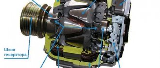
Generator structure
Regardless of the make and model of the car, the type of car generator, a voltage regulator is always included in the design, allowing it to maintain operation regardless of the rotor speed. The adjustment is carried out by changing the strength of the electric current on the rotor winding.
Generator components (diagram):
- The stator (housing) is the stationary part of a car generator.
- There are three windings, they are connected into one by a star, which generates a three-phase alternating voltage.
- A rotor on the blades of which a magnetic field and EMF are formed.
- Three-phase rectifier - semiconductor diodes that convert voltage. One side of the diodes is conductive, the other has an insulated surface.
- Automatic voltage regulation device.
Car generator rotor
Three windings can significantly reduce ripple due to phase overlap.
Two-level regulation scheme
It consists of three main elements: a generator, a battery, and a rectifier. There is a magnet inside the device, the winding of which is connected to the controller. Metal springs are used as setting devices, and movable levers are used as comparing devices. The contact group is used as a measuring device, and a constant resistance as a control device.
Two-level voltage regulator
Operating principle of a two-level regulator
When voltage and electromagnetic field occur, the signals are compared. A spring is used as a comparison device, which acts on the lever arm. The magnetic field acts on the lever in several directions (closes, opens, remains unchanged), after which the regulator circuit operates depending on the voltage value.
When the signal goes beyond the operating range, the contacts open.
A constant voltage is connected to the circuit.
In this case, less current is supplied to the winding and the voltage is stabilized. If the contacts initially short, indicating low voltage, the current increases and the generator continues to operate normally.
Disadvantages of mechanical models:
- rapid wear of parts;
- use of electromagnetic relays.
Electronic regulators
They work identically to analog models, except that the mechanical elements are replaced with digital sensors. Instead of electromagnetic classical relays, thyristors, triacs, transistors, etc. are used. The sensitive element is a system of constant resistors installed on a voltage divider.
Electronic regulator circuit
The principle of operation is as follows: when voltage is applied to the thyristors, the output signals are compared. The executive body, depending on the received data, closes or opens, if necessary, including additional resistance in the circuit.
Advantages of electronic models:
- high adjustment accuracy;
- the regulator is installed in a single unit with brushes, which saves space and simplifies diagnostics, repair and replacement of equipment;
- increased reliability and durability;
- finer tuning of the device;
- Semiconductor diodes are used as rectifiers, which ensure stability of the output voltage;
- the driving element is made in the form of a zener diode.
For new car models, it is advisable to use more advanced control systems due to a more complex technical device.
Stories from our readers
“Fucking basin. "
Hi all!
My name is Mikhail, now I’ll tell you a story about how I managed to exchange my two-wheeler for a 2010 Camry. It all started with the fact that I began to be wildly irritated by the breakdowns of the two-wheeler, it seemed like nothing serious was broken, but damn it, there were so many little things that really started to irritate me. This is where the idea arose that it was time to change the car to a foreign car. The choice fell on the melting Camry of the tenth years. Yes, I had matured morally, but financially I just couldn’t handle it. I’ll say right away that I am against loans and taking a car, especially not a new one, on credit is unreasonable. My salary is 24k a month, so collecting 600-700 thousand is almost impossible for me. I started looking for different ways to make money on the Internet. You can’t imagine how many scams there are, what I haven’t tried: sports betting, network marketing, and even the Vulcan casino, where I successfully lost about 10 thousand ((The only direction in which it seemed to me that I could make money was currency trading on the stock exchange, they call it Forex. But when I started delving into it, I realized that it was very difficult for me. I continued to dig further and came across binary options. The essence is the same as in Forex, but it’s much easier to understand. I started reading forums, studying trading strategies. I tried it on a demo account, then opened a real account. To be honest, I didn’t manage to start earning money right away, until I understood all the mechanics of options, I lost about 3,000 rubles, but as it turned out, it was a precious experience. Now I earn 5-7 thousand rubles a day. I managed to get the car buy after half a year, but in my opinion this is a good result, and it’s not about the car, my life has changed, I naturally quit my job, I have more free time for myself and my family. You’ll laugh, but I work directly on the phone)) If If you want to change your life like me, then here’s what I advise you to do right now: 1. Register on the site 2. Practice on a Demo account (it’s free). 3. As soon as you get something on the Demo account, top up your REAL ACCOUNT and go to REAL MONEY! I also advise you to download the application to your phone, it’s much more convenient to work from your phone. Download here.
2. MAX - both diodes are used 3. MID - only diode D2 is used. In such a scheme, any switching is painless - in intermediate states of the toggle switch there will be mode No. 2.
I connected the red wire to the “In” terminal, and the black wire to the “Out” terminal.
- When toggle switch S1 is in position “1” , the generator operates in normal mode.
- In position “3” of toggle switch S1, one Schottky diode is connected. The voltage at the generator output increases by 0.3-0.4V.
- When toggle switch S1 is in position “2” , two Schottky diodes connected in series are connected to the generator circuit. The generator output voltage increases by (0.3-0.4V)*2.