Features of the operation of dimensions on the VAZ 2114
Being the ideological heir of the first generation, the “fourteenth” inherited from it many technological solutions, including external lighting devices. Thus, the dimensions on the VAZ 2114 are located in the corner areas of the body at the front and rear, which, according to technical regulations, are included in the general blocks of lamps and headlights.
At the same time, there are several features that should be noted when describing the side lights on the VAZ 2114:
- on/off is carried out by a button in the exterior light control module;
- when the lights are on, the switch is illuminated by a green indicator diode;
- The rear lights of the VAZ 2114, unlike the front ones, light up in red, in accordance with Russian road safety standards.
A dedicated fuse block is responsible for the correct operation of the side lamps on this Lada, which can be found in the engine compartment next to the engine. Accordingly, most often motorists who notice non-functioning dimensions on the left or right side of the car are faced with a failed fuse.
The easiest way to diagnose the failure of fuse F10, since it simultaneously acts as a warning lamp, whereas if a pair of dimensions on the left side of the car is not working, fuse F11 will most likely have to be replaced.
Causes of malfunctioning rear lights
Troubleshooting a situation with non-working side lights is the primary task of the car owner, as this not only creates a dangerous situation on the road, but also, in the end, is fraught with a fine from the traffic police.
To find out why the dimensions of the VAZ 2114 do not light up, you need to focus on three main factors:
- Burnt out lamp.
- Loose contact of the power wire.
- Broken wiring leading to the gauge.
The first case is the most common, and the problem is solved by simply replacing the light bulb, fortunately, they are sold everywhere and cost little money.
You can confirm the second reason without disassembling the device by simply tapping on the size: the moment you press it to the contact, the lamp will light up, and vice versa, it will go out in the free position. If disassembling the device did not reveal any oxidation with carbon deposits, a burnt-out lamp or a loose terminal, but the rear marker of the VAZ 2114 still does not light up, we can talk about faulty wiring.
Heated rear window, what is it for?
Rear window heating for any car will be appropriate not only in the cold season, but also during rain. The performance of this element is a guarantee of comfortable movement at any time of the year.
The following two tabs change content below.
- About the expert:
Renault car expert
I own a Renault Megane 2, before that there were Citroens and Peugeots. I work in the service area of a dealership, so I know the car inside and out. You can always contact me for advice.
Replacing a broken light bulb
To repair the rear lights of a VAZ 2114, you need to follow a number of simple recommendations:
- turn off the vehicle's power supply;
- open the trunk, remove the decorative trim;
- Squeeze the latches and remove the contact panel of the entire flashlight;
- press down the faulty lamp and turn it counterclockwise to remove it.
Next, it is advisable to “ring” the lamp with a tester to make sure that it was its malfunction that was the cause of the problem, after which it should be replaced with a new analogue, and you can begin assembling the lamp in the reverse order.
Fiat Albea. Knocking and clicking noises when turning the car
| Possible causes of malfunction | Troubleshooting |
| Worn outer drive joint | Remove the drive and check the joint. If necessary, replace the hinge or drive assembly |
| Lack of lubrication in the joint | Inspect the case. Remove the drive and check the hinge. Apply sufficient new lubricant to the joint and replace the damaged joint cover. If there is play, replace the hinge or drive assembly |
| The intermediate bearing is severely worn | Remove the intermediate support bracket and check the play in the bearing. If necessary, replace the intermediate bearing |
Additional Tips
Sometimes VAZ 2114 owners are faced with the opposite situation, when the rear lights themselves work, but the indicator on the power button does not: this is almost always a sign of a faulty wiring in the interior panel. You can deal with the problem by removing the entire key block and thoroughly wiping its contacts.
In general, the side lights on this VAZ model should not often fail, since the contact pads for their fuses were specially increased in width in order to ensure a tight connection.
In addition, experts advise that in frequent breakdowns of dimensions there is a malfunction in the mounting block itself or its electrical circuit. Such a problem must be eliminated as soon as possible to eliminate the risk of a wiring fire.
Finally, you should pay attention to the tightness of the entire rear light unit and prevent moisture from getting inside, which can easily cause the lamp contacts to sour.
Fiat Albea. Vibrations when accelerating and decelerating
| Possible causes of malfunction | Troubleshooting |
| Worn inner joint | Replace the hinge or drive assembly |
| The intermediate shaft is deformed | Replace the drive assembly |
| Worn intermediate bearing | Remove the intermediate support bracket and check the play in the bearing. Replace the faulty bearing |
Fiat Albea.
Battery faults
| The battery is discharged. The starter does not turn the engine crankshaft or turns it slowly, the lamps are dim. | |
| Cause of malfunction | Elimination methods |
| The car has not been used for a long time | Charge the battery using a charger or in another vehicle |
| Belt tension is loose | Tighten the generator drive belt. |
| When the engine is turned off, many electrical consumers are running (head unit of the sound reproduction system, etc.) | Reduce the number of consumers running on battery power |
| Damage to the insulation of electrical circuits, current leakage across the battery surface | Check the leakage current (no more than 11 mA when consumers are disconnected), clean the surface of the battery. Beware of acid! |
| Generator faulty | See Generator Troubleshooting |
| Short circuit between the plates (“boiling” of the electrolyte, local heating of the battery) | Replace the battery |
Fiat Albea.
The low battery indicator light is on
| The battery low charge indicator is on. The vehicle's on-board voltage is below 15 V. | |
| Cause of malfunction | Elimination methods |
| The generator drive belt tension is loose | Tighten your belt |
| The voltage regulator is faulty. | Replace regulator |
| The diodes of the rectifier unit are damaged | Replace the rectifier unit |
| The connection of the excitation winding terminals with the slip rings is broken, there is a short circuit or a break in the winding | Solder the leads, replace the generator rotor or generator assembly |
| Open circuit or short circuit in the stator winding, shorting it to ground (when shorted, the generator howls) | Check the winding with an ohmmeter. Replace the stator or generator assembly |
Fiat Albea.
The vehicle's on-board voltage is higher than 15.1
| The vehicle's on-board voltage is higher than 15.1 V | |
| Cause of malfunction | Elimination methods |
| Damaged voltage regulator | Replace voltage regulator |
Dimensions do not work on VAZ 2114
According to these Rules of the Road, on any moving vehicle, including the VAZ-2114, the headlights must be turned on, along with which the side lights must also be turned on. In addition, they must be turned on when the car is stopped or parked on the road in the dark and in conditions of insufficient visibility. Therefore, they must always be in good working order.
The electrical circuit of the side lights of the VAZ-2114 is not so complicated and, if desired, any self-respecting driver will be able to find a malfunction associated with the failure of its operation. To do this, you need to know that terminal No. 1 of the side light switch is always supplied with positive voltage from the battery, bypassing the ignition switch. If the side light switch key is in the on position, then electric current flows to two fuses F10 (7.5A) and F11 (7.5A), which respectively protect the electrical circuits of the left (F10) and right (F11) side lights. The further path of the current lies to relay K4 (lamp health monitoring relay), and then to the front and rear side lamps.
Removal and installation of transmission Ford Focus 2 2005-2008
- Repair manuals
- Ford Focus 2 2005-2008
- Removing and installing the gearbox
The main malfunctions, to eliminate which it is necessary to remove the manual transmission from the car, are the following:
– increased (compared to usual) noise;
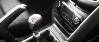
– difficult gear shifting;
– spontaneous shutdown or unclear gear shifting;
– oil leakage through seals and gaskets.
In addition, the gearbox is removed to replace the clutch, flywheel and engine crankshaft rear oil seal.
An automatic transmission is removed for almost the same reasons as a manual transmission, with the exception of the need to replace the clutch and flywheel, which are absent in this case. The methods for removing and installing manual and automatic transmissions are almost the same and are described using the example of a manual transmission. The difference lies in the size and number of transmission control drive cables, as well as in the presence of hydraulic hoses in the automatic transmission that connect the box to the cooling radiator.
| Useful tips The work of removing and installing the gearbox is very labor-intensive, so first make sure that its malfunctions are not caused by other reasons (insufficient oil level, defects in the clutch drive, loose gearbox, etc.). The gearbox is quite heavy and its shape is awkward to hold, so we recommend removing it with an assistant. |
You will need: keys “8”, “10”, “13”, “15”, a socket “13” with a ratchet, a screwdriver with a flat blade.
1. Place the vehicle on a lift or inspection ditch.
2. Remove the air filter (see “Removing and installing the air filter and intake silencer”).
3. Remove the engine splash guard (see “Removing and installing the engine splash guard”).
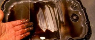
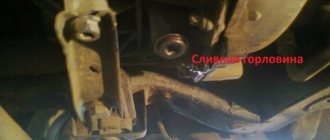
4. Drain the oil from the gearbox (see “Changing the oil in the gearbox”).
5. Remove the front wheel drives (see “Removing and installing the front wheel drives”).
6. Disconnect the gearbox control cables from the gearbox (see “Replacing the gearbox control cables”).
7. Remove the air filter mounting bracket (see “Replacing the left power unit suspension support”).
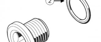
8. Disconnect the wiring harness block from the reverse light switch (see “Checking and replacing the reverse light switch”)…
| 9. ...pry it out with a screwdriver... | 10. ...disconnect the holder of the reverse light switch wiring harness from the gearbox housing and move the harness to the side. |
11. Disconnect the wiring harness block from the speed sensor (see “Checking and replacing engine control system sensors”).
| 12. Using a screwdriver, remove the spring clamp of the tip of the hydraulic clutch release hose... | 13. ...and disconnect the hose from the hydraulic drive tube. |
| Note Take measures to prevent hydraulic fluid from leaking out of the clutch release hydraulic tube (for example, by plugging the hole in the tube with a rag or a wooden plug). |
| 14. Remove the bolt securing the hose brackets to the gearbox housing... | 15. ...and move the bracket along with the hoses to the side. |
| 16. Remove the bolt securing the ground wires to the body bracket... | 17. ...disconnect the wires from the bracket and move them to the side. |
18. Unscrew the fastening bolts and remove the starter from the clutch housing without disconnecting the wires from it (see “Removing and installing the starter”). Move the starter to the side and secure it in any way so that it does not interfere with further work.
19. Place a reliable support under the engine or hang it using a lifting mechanism. Install a similar support under the gearbox.
| 20. Remove the gearbox breather from the edge of the cage of the left power unit support. | 21. Unscrew the nut securing the “mass” wire to the stud securing the bracket for the left suspension support of the power unit... |
| 22. ...remove the wire end from the stud and move the wire to the side. | 23. Remove the two bolts and the stud securing the left power unit suspension support bracket to the gearbox housing... |
| 24...and remove the support along with the bracket. | 25. Remove one bolt at a time securing the gearbox housing to the engine from the top left... |
| 26. ...and on the right... | 27. ...two bolts on the left side... |
| 28. ...and five bolts from below. | 29. Remove the rear power unit suspension mount (see “Replacing the rear power unit suspension mount”). |
| 30. Move the gearbox back until the input shaft of the box comes out of the clutch driven disc hub. | 31. Move the box as far back as possible, remove the support from under it and, tilting the back of the box down, remove it from the car. |
| Warning When removing the gearbox, do not rest the end of the input shaft on the petals of the diaphragm spring so as not to deform them. |
32. Install the gearbox and all removed parts and assemblies in the reverse order of removal.
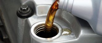
| Useful tips Before installing the gearbox, we recommend lubricating the input shaft splines with a thin layer of refractory grease. Check how the clutch driven disc is aligned using a special mandrel (see “Removing and installing the clutch”). |
33. Fill the gearbox with oil (see “Changing the gearbox oil”).
34. Remove air from the clutch release hydraulic drive (see “Bleeding the clutch release hydraulic drive”).
35. If necessary, adjust the gearbox control drive (see “Adjusting the gearbox control drive”).
↓ Comments ↓
Section 1. Vehicle design
General information about the car Passport data Car keys Controls Heating (air conditioning) and interior ventilation Doors Seat belts Seats Steering wheel adjustment Rear view mirrors Interior lighting Sun visors Interior storage compartments Hood Gearbox control Roof rack
Section 2. Recommendations for use
Safety rules and recommendations What you need to have in your car Running in the car Operating the car during the warranty period Preparing the car for departure Filling the car with gasoline Using a jack Towing the car
Section 3. Problems along the way
The engine does not start Malfunctions of the fuel injection system Idle has disappeared Interruptions in engine operation Diagnostics of the engine condition by the appearance of the spark plugs The vehicle moves jerkily The vehicle accelerates poorly The engine stalls while driving The oil pressure has dropped Engine overheating The battery does not recharge Starting the engine from external power sources Malfunctions of electrical equipment Extraneous knocking noises appear Problems with the brakes Puncture of a wheel
Section 4. Maintenance
General provisions Daily maintenance (EO) First maintenance (MOT-1) Second maintenance (MOT-2)
Section 5. Engine
Design features Possible engine malfunctions, their causes and solutions Useful tips Checking compression in the cylinders Removing and installing the engine mudguard Replacing the power unit suspension mounts Installing the piston of the first cylinder to the TDC position of the compression stroke Removing, installing and troubleshooting the flywheel Replacing engine seal parts Adjusting clearances in the drive valves Cylinder head Removal and installation of the engine Lubrication system Cooling system Exhaust system Engine power supply system Fuel vapor recovery system
Section 6. Transmission
Clutch Gearbox Front wheel drives
Section 7. Chassis
Front suspension Rear suspension
Section 8. Steering
Design features Possible malfunctions of power steering, their causes and solutions Steering column Steering rods Steering mechanism
Section 9. Brake system
Features of the device Possible malfunctions of the brake system, their causes and solutions Bleeding the hydraulic drive of the brake system Checking the position of the brake pedal Master brake cylinder Vacuum brake booster Replacing hoses and tubes of the hydraulic brake drive Removing and installing the brake pedal Brake mechanisms of the front wheels Brakes of the rear wheels Parking brake Anti-lock brake system
Section 10. Electrical equipment
Design features Diagnostics of malfunctions of on-board electrical equipment Mounting blocks Battery Generator Starter Ignition switch (lock) Engine control system Lighting, light and sound alarms Replacement of the windshield window wiper motor Replacement of the tailgate window wiper motor Removal and installation of the windshield washer Replacement of the front door window regulator motor Removal and installation of the electric motor of the radiator fan of the engine cooling system Replacement of the additional resistance of the radiator fan of the engine cooling system Removal and installation of the electric motor of the heater Replacing the additional resistance of the electric heater fan Electric heating of the glass of the rear window (tailgate) Instrument cluster Instrument panel switches Replacement of the control unit for electric windows and electric mirrors Car audio system Replacement of sensors and switches
Section 11. Body
Design features Possible body malfunctions, their causes and solutions Removal and installation of the radiator lining Removal and installation of wheel mudguards and wheel arch liners Removal and installation of bumpers Removal and installation of the front fender Removal and installation of the engine compartment frame and front bumper beam Removal and installation of the air intake and drainage box grille shield Hood Side doors Tailgate of hatchback cars Fuel tank filler hatch cover Seats Removal and installation of floor tunnel lining Passive safety system (SRS) Rear view mirrors Instrument panel Heater and air conditioner Interior fittings Removal and installation of interior linings Removal and installation of trunk linings Windshield wiper windshield Windshield wiper for tailgate window Replacing fixed glazing of the body Removing and installing the battery mounting shelf Caring for the body
Section 12. Wheels and tires
Technical characteristics Marking of rims Marking of tires Changing wheels Wheel nuts Breaking in tires Storing tires Balancing wheels Snow chains Spare wheel Checking tire pressure Checking tire tread Checking valves Checking radial and lateral runout of rims
Section 13. Purchase of spare parts
Engine oil Lubricants Coolants Brake fluid Fuel filter Air filter Engine oil filter Spark plugs
Section 14. A trip to the service station
Section 15. Winter operation of the vehicle
How to prepare a car for winter Recommendations for starting the engine in severe frost What is useful to buy for winter Useful winter tips
Section 16. Preparation for technical inspection
Recommendations List of malfunctions and conditions under which the operation of vehicles is prohibited Changes to state standards regulating the maximum permissible content of harmful substances in the exhaust gases of motor vehicles
Section 17. Tips for a novice auto mechanic
Safety precautions when carrying out repair work Tools Before starting work Restoring threaded connections Tips for body repair
Applications
Appendix 1. Tightening torques of threaded connections, Nm Appendix 2. Overall dimensions (mm) of Ford Focus II cars with sedan and station wagon bodies Appendix 3. Technical characteristics of engines and performance indicators of cars depending on the type of engine used Appendix 4. Air pressure in cold tires Appendix 5. Filling volumes, l
Electrical circuit diagrams
Diagram 1. Windshield wiper and washer connections Diagram 2. Battery charging system connections Diagram 3. Brake system hydraulic drive system connections Diagram 4. Ventilation, heating and air conditioning system connections Diagram 5. Engine starting system connections Diagram 6a. Speed control system connections Diagram 6b. Speed control system connections Diagram 7a. Engine control system connections Scheme 7b. Engine control system connections Scheme 7c. Engine control system connections Scheme 7d. Engine control system connections Scheme 7d. Engine control system connections Diagram 7e. Engine control system connections Scheme 7g. Engine control system connections Scheme 8a. Air conditioning system connections Diagram 8b. Air conditioning system connections Diagram 9. Power steering system connections Diagram 10a. Anti-lock brake system (ABS) connections Scheme 10b. Anti-lock brake system (ABS) connections Diagram 11. Vehicle Dynamic Stability System connections