How to check
After turning the ignition key to the “ON” position, the main relay is turned on and power is supplied to everything except the starter system of the vehicle. At this moment, a buzzing sound will be heard in the area of the gas tank - the operation of the fuel pump. Further turning of the key will close the contacts of the starter relay and start it. When you repeatedly try to turn the starter, such a sound will most likely not be heard, and this is not a malfunction. The fuel line is filled with gasoline, and the pressure sensor will not allow the pump to start when the engine is not running.
To check the serviceability, we use a 12-volt lamp with a current consumption of no more than 0.25 A. We connect pieces of insulated copper wire to the contacts. Using a more powerful lamp may damage the ECU chips.
We check the presence of power at the control contacts of the relay coil - terminals 85 and 86, alternately touching the negative contact of the battery. If there is power at one of the contacts, the lamp will flash, which means the control circuit is working properly. If you connect the lamp directly to the control terminals of pair 85-86, the next time you turn on the ignition, the lamp will light up for 15-20 seconds. Otherwise, you need to check the serviceability of the wiring leading to the terminals and the corresponding fuses, or proceed to check the operation of the computer.
If at the first stage of the test the serviceability of the control circuits of terminals 85 and 86 is established, at the second stage of the test we check for the presence of +12 V on leg 87 of the fuel pump control relay relative to ground. The lamp does not light up - check the circuit fuse and wiring. If there is voltage at the terminal, we close terminals 87 and 30 with a jumper, thereby simulating the situation when the relay is activated, as a result, the fuel pump should start and start working. If the result is negative, we will try to start the pump directly and touch one of the wires of the control lamp to the fuel pump terminals in turn, and attach the second wire to the body ground. If the lamp lights up, most likely there is a problem with the performance of the pump itself, otherwise you need to check the power wiring of the fuel pump.
One of the possible malfunctions of the fuel pump relay is sticking of contacts 86 and 30, due to which the fuel supply will continue even after the engine is turned off. The cause is usually the melting of the plastic of the holders and subsequent melt soldering of a pair of contacts. In this case, the relay must be replaced at the first opportunity.
The video describes in detail how to check the fuel pump:
- What malfunctions are prohibited from operating a car?
- How dual-zone climate control works
- How to make a winch from a starter with your own hands: video instructions and drawing
- Why do you need an air filter in a car?
Malfunctions and checking regulators on a VAZ
In VAZ-2110 cars, the voltage regulator breaks quite rarely, but if this happens, signs of its malfunction may be:
- Failure of the control panel backlight.
- Exceeding the battery charging voltage.
- Insufficient battery charge voltage.
If the voltage regulator relay of the VAZ-2110 breaks down, the fuses responsible for the safety of the power supply circuit of the instrument panel may blow out. If the backlight lamps do not light up when the ignition is turned on, there is a possibility that the LV is to blame.
The same can be assumed when the voltmeter needle, indicating the battery charge level, deviates from its usual position, i.e., shows higher or lower voltage.
To make sure that it is the LV that has failed, and not the generator itself, it should be checked separately. To do this, you will need to disconnect it from the main device. The procedure is as follows:
- Remove the negative terminal from the battery.
- We find the place where the launch vehicle is attached to the generator. Unscrew the 2 screws that secure it.
- Disconnect the yellow wire going from the regulator to the generator.
- We dismantle the launch vehicle.
To diagnose the device, you will need a power supply with the ability to adjust the output voltage, a light bulb (12 V) with a socket and a pair of wires. The verification algorithm is as follows:
- We assemble a “control” from a lamp and wires and connect it to the regulator brushes.
- Set the voltage on the power supply to 12 V.
- We connect the “plus” from the power supply to the “D” terminal of the regulator, and the “minus” to its “ground”.
- We look at the lamp: it should be lit.
- We increase the voltage on the power supply to 15-16 V. If the regulator is working properly, the lamp should go out. If this does not happen, the LV must be replaced.
What is a relay for?
Fuses and relays
Replacing the starter relay on a VAZ 2110
The traction relay ensures that the drive gear starts. Starting occurs in clutch with the gear mechanism of the crankshaft flywheel. It also provides power to the starter motor. When the starter is turned on, energy begins to be transferred from the battery. The energy path passes through the ignition switch.
VAZ 2110 additional starter relay
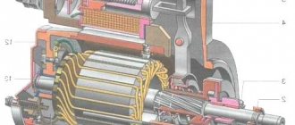
In this way, power is supplied to each winding of the traction relay. Windings have two types:
As soon as the process of closing the relay contacts takes place, the retractor winding is turned off. A working relay has a voltage limit that should not exceed 8 V. The temperature during this process should not exceed 25 degrees Celsius
If the voltage when starting the relay exceeds this indicator, then you should pay attention to the drive and the traction relay itself. They may become damaged or stop working
The traction relay can be visually examined. Perhaps the breakdown can be seen with the naked eye, but the starter will have to be dismantled and disassembled.
VAZ 2110 starter lock relay
Three-level voltage regulator VAZ-2110
Now let's go back a little. If you discover a faulty LV and decide to replace it, do not rush to buy a stock device. There is a good alternative to it - a three-level regulator. How is it different from the usual one? It allows you to regulate the output voltage depending on the air temperature, thereby optimizing the load on the battery.
Modes are switched using a toggle switch in the following ranges:
- 13.6 V (minimum) – for operation at temperatures above +20 o C;
- 14.2 V (normal) – from 0 o C to +20 o C;
- 14.7 V (maximum) – for operation at temperatures below 0 o C.
The three-level voltage regulator VAZ-2110 consists of two parts: the pH itself and the brush holder. The latter is installed directly on the generator and is connected to the former using a wire. The regulator, equipped with a toggle switch, is attached to the car body in the engine compartment in a convenient place. You can install the launcher yourself using the instructions that come with it.
Fuse and relay box
Fuses and relays in Lada Kalina
The fuse and relay box is located on the left, lower part of the instrument panel. It is accessible by pressing the button and folding the lid down. To remove fuses, there are special non-conductive pliers in the upper left part of the mounting block.
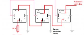
1 - K5 - high beam relay. If the high beams in two headlights do not work, check this relay. If one of the high beam headlights does not work, check fuses F3 and F13, as well as the lamps and the high beam switch.
2 - K4 - low beam relay. If the low beam in both headlights does not work, check this relay. If only one low beam headlight does not work, check fuses F2 and F12, as well as the lamps themselves and the light switch.
3 - K1 - lamp health control relay.
4 - non-conductive tweezers for removing fuses.
5 - power window relay. If your power windows stop working, check this relay. It could also be in fuse F5, or in the window lift drive system itself. To get to the mechanism, you need to remove the door trim. Check the electric motor, the appearance of the gears and the absence of binding of the mechanism.
6 - K3 - turn signal and hazard warning relay. If your turn signals or hazard lights do not work, check this relay and fuse F16, as well as the turn signal lamps themselves and their switch.
7 - starter relay. If the car does not start and the starter does not turn, check this relay. It could also be a dead battery, as well as the starter mechanism itself.
8 - backup fuses.
9 - fog lamp relay. If the fog lights do not work, check this relay and fuses F4 and F14. Also check their connection diagram, the serviceability of the wiring and connectors, as well as the lamps in the headlights and the power button.
10 - K2 - windshield wiper and washer relay. If your windshield wipers or windshield washer are not working, check this relay. Also check the wiper motor, washer pump and washer fluid level in the washer reservoir.
11 - K7 - rear window heating relay. If the heating does not work and the rear window fogs up, check this relay and fuses F8 and F9. Also check the connection contacts to the terminal points of the heating elements (at the edges of the glass at the rear pillars). If everything is in order, but the heating does not work, the issue may be in the wiring (the wires are frayed or something else).
12 - K6 - add. relay, ignition relay. If your ignition does not turn on or is having problems with it, check this relay. This relay protects the ignition switch contacts from burning. Also check the ignition switch itself and the contact group.
13 - row of fuses F1-F10
14 - row of fuses F11-F20
What is the advantage of three-phase regulators
The main advantage of such devices is the ability to preserve the life of the car battery. This is very important for any driver. The list of benefits does not end there:
- Eliminates heating problems.
- In cold weather the engine will start faster.
- Problems with alarms disappear, which quite often happens to vehicle owners. Such surprises especially happen in winter.
- The power of light emission from lamps increases. Visibility will improve both with low and high beams.
- The regulator can also affect the operation of the vehicle's heating system. There is an established opinion among experienced drivers that the stove works much better with a fully charged battery.
- Some car enthusiasts have noted that power windows work faster with a working battery.
As you can see, a high-quality battery with an additional three-level regulator can save you from a lot of problems.
What is a relay
Fuses and relays VAZ 2107. Electrical faults
The first relay was invented in the mid-19th century by Joseph Henry, the same Henry after whom we now name units of inductance. Nowadays, relays are quite common, they can mainly be found in cars, various household tools, in production, etc.
A relay is an electromagnetic switch designed for switching in electrical circuits when the input value changes abruptly. At first glance it sounds scary, but I assure you, it only seems so. A relay is an ordinary switch, only it is triggered by any influence, for example, when a current appears in the circuit (an abrupt change in the input value). The circuit through which the current flows, causing the relay to operate, is called the control circuit, and the circuit through which the relay switches is called the controlled circuit. A relay is a kind of amplifier because it requires minimum values of current and voltage to operate, despite the fact that in the controlled circuit these values can be much higher.
There are DC and AC relays. AC relays operate when a current of a certain frequency flows. Structurally, they are almost no different from DC relays, except that the core is made of sheets of electrical steel in order to reduce losses due to hysteresis and eddy currents. DC relays are either neutral or polarized. Neutral ones are triggered when current flows in any direction, and polarized ones only in one specific direction.
Device
The simplest relay is a mechanism consisting of an armature. electromagnet and contacts. The principle of operation is that when current passes through an electromagnet, an electromagnetic force is generated in it, which causes the armature to connect the contacts. After the current in the circuit becomes less than the required value, the spring returns the armature to its place, thereby separating the contacts. The relay itself may contain other elements, such as a resistor, which serves to more clearly turn on the relay, or a capacitor that is connected in parallel to the contacts and serves to reduce interference and sparking.
For a clear example, consider a domestically produced automotive relay 75.3777-10.
External inspection does not present anything interesting, except for the relay diagram, which actually shows which winding contacts (86 and 85 are the control circuit) and which are connected. (87 and 88 controlled circuit). The maximum current for which the relay is designed (30A) and the rated voltage at which it operates (12V) are also indicated. By the way, the manufacturer indicates that the winding current should not exceed 0.2A. As you can see, the current in the control circuit (winding) is significantly less than the current in the controlled circuit.
After carefully studying the exterior, let's move on to the most interesting part - the insides.
As you have seen for yourself, the relay is a fairly simple, but very useful device.
Thank you for your attention
Reasons for replacement
Relay replacement is needed in the following cases:
- The brushes are worn out. By the way, this is the main reason. The fact is that due to their wear, contact with the relay is lost, so due to lack of power, the generator will stop working.
- A breakdown is observed in the circuit, which leads to an increase in voltage in the system.
- Wire breaks causing loose contacts.
- Damage to the housing or fastenings. This is not something to joke about, as it can lead to an unwanted short circuit.
Relay replacement
Note: It is usually black and is attached to the generator with a yellow wire.
- Disconnect the negative terminal of the battery.
- Unscrew the two bolts securing the generator.
- Remove the yellow wire going to the relay from the generator.
- Remove the relay. Examine it carefully. If the brushes are worn out, replacement cannot be avoided.
- If any of the wires are broken or there are holes on its surface, then you can only get by by replacing them.
Note: you can simply insulate them without even replacing them with new ones. Although the relay is inexpensive - only 70 rubles.
- Check the new voltage regulator, and then attach it to the generator.
- Reconnect the yellow wire and battery terminal.
As noted earlier, you can replace the relay with your own hands. The main thing is to familiarize yourself with the work process in advance so that questions do not arise later. To do this, you can find photos in various auto repair magazines. It’s much easier to use videos, of which there are many on the Internet. Our instructions will also help in this difficult matter. But the price of home repairs will not exceed 100 rubles.
Notes
Categories:
- Switching devices
- Relay
- Relay protection
- Automation
Wikimedia Foundation. 2010.
See what “Relay” is in other dictionaries:
relay - , constant; Wed An automatic device that closes or opens electrical circuits in response to certain phenomena to which it is designed to respond. Switch relay. Electromagnetic relay. ◁ Relay, oh, oh. R oe ... ... Encyclopedic Dictionary
relay - uncl. Wed relais < relayer change, replace. unit Traveling from one station to another on horseback. We go to one station, then another, a man gets into the stagecoach, perhaps a very respectable one, but without a nose, the Englishwoman suffered for two, three relays and began to beg... Historical Dictionary of Gallicisms of the Russian Language
relay - a device for automatic switching of electrical circuits based on an external signal. It consists of a relay element (usually with two stable states) and a group of electrical contacts that close (or open) when the state changes... ... Encyclopedia of Technology
RELAY - A sensitive electromagnetic device used in a telegraph. Dictionary of foreign words included in the Russian language. Chudinov A.N. 1910. RELAY is a very sensitive electromagnetic device through which. the current of the telegraph line passes and... ... Dictionary of foreign words of the Russian language
RELAY - (French relais) a device for automatic switching of electrical circuits based on an external signal; consists of a relay element (with two stable equilibrium states) and a group of electrical contacts that close (or open) when... ... Big Encyclopedic Dictionary
RELAY/ - (re), uncl. Wed (French relais) (physical tech.). An electromagnetic device that controls the action of something. signaling or other apparatus, machine or network by closing or opening an electrical circuit. Cathode relay (radio) is the same as cathode... ... Ushakov's Explanatory Dictionary
relay - , uncl. Wed (French relais) (physical tech.). An electromagnetic device that controls the operation of some signaling or other device, machine or network by closing or opening an electrical circuit. ❖ Cathode relay (radio) is the same as... ... Ushakov's Explanatory Dictionary
RELAY - RELAY, several Wed (specialist.). A device for closing and opening an electrical circuit. Electromagnetic river | adj. relay, oh, oh. Ozhegov's explanatory dictionary. S.I. Ozhegov, N.Yu. Shvedova. 1949 1992 ... Ozhegov's Explanatory Dictionary
relay - noun number of synonyms: 11 • barorele (1) • hydrorelay (1) • kipp relay (1) • ... Dictionary of synonyms
relay - for controlling electrical circuits; relay A relay action device designed to make changes in electrical circuits (usually control, signaling and communication circuits) ... Polytechnic terminological explanatory dictionary
- Control and protection relays. Volume 1. Control relay (+ CD-ROM). Control and protection relays belong to the class of low-current switching devices and are used in electrical devices as a control and protection element. Control relay and… Read more Buy for 2652 RUR
- Control and protection relays. Volume 2. Protection relays. Directory. Control and protection relays belong to the class of low-current switching devices and are used in electrical devices as a control and protection element. Control relay and… Read more Buy for 1520 UAH (Ukraine only)
- Control and protection relays. Volume 2. Protection relays. Directory. Control and protection relays belong to the class of low-current switching devices and are used in electrical devices as a control and protection element. Control relay and… Read more Buy for 1469 RUR
Other books on request “Relays” >>
What is it used for?
This protective device is necessary, just like a circuit breaker. However, this device has a different purpose - to monitor voltage.
Overvoltage in the network is a common cause of failure of expensive equipment, the repair and replacement of which costs a pretty penny, since failure from overvoltage is not covered by warranty. And as a rule, such surges last a few seconds until the protection at the substation is triggered; this is quite enough for the electronics in the house to fail. Look at how many devices you have plugged in, even if you don’t use them, at the moment, they are all a potential threat.
To avoid this, a voltage relay has been created that monitors the state of the electrical potential in your apartment around the clock, and will instantly de-energize the network in the event of an abnormal change.
Pay attention to the single-phase relay RN-104 volt control from the manufacturer Novatek Electro. Easy to set up and operate, it will guard the electrical network of your home or apartment
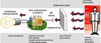
Below we will look at the design and operating principle of a voltage control relay.
What to do if the voltage relay fails?
If you are new to electronics, then such an undertaking will be quite difficult.
As we mentioned earlier, the main element of the circuit is a certain number of diodes. Finding three-stage switches for them is quite problematic. In addition, you need to correctly calculate and install radiators for cooling. Otherwise, the risk of diode burnout increases significantly.
During the development of the regulator, long wires will be needed, because the connection is made directly to the device through the cover.
Additionally, you will need to make or find a suitable plastic case for such equipment. All internals must be securely fastened inside the device.
It happens that the relay fails at the most inopportune moment, when you still have a drive home and the battery is not charging. The battery capacity in economical mode can ensure fairly long engine operation, which will allow you to get to the repair site without any problems. Below we will provide a list of recommendations that will help you drive, as they call it, “on battery power” and not stall.
- If the battery is overcharged, the relay must be disconnected from the circuit. To do this, the contact wires are removed from it and left hanging. In the case of the “ten”, it is enough to unplug the plug with the wire from the generator brush connector. Thus, battery charging is turned off, and further movement will no longer harm the battery.
- Many experts suggest going the other way - turning off the generator excitation winding. To do this, remove the corresponding fuse. However, this can be done if you know where the fuse is located.
- If the battery is weakly charged, then there is practically no reason to panic. To get to your destination, you need to maintain high speeds in order to, at least a little, bring the voltage value to the nominal value. Before stopping the engine, it is recommended to maintain the speed at 3000 rpm for a few seconds using the gas pedal. This will prepare the battery for the next start.
- Avoid using music, power windows, headlights (especially high beams), and other electrical devices unless their use is absolutely necessary. This will save battery power well.
Relay regulator VAZ
- disconnect the negative terminal from the battery;
- disconnect the drive block from the terminal marked “D”;
- unscrew the nut, which is located under the rubber boot (it needs to be moved a little to the side);
- disconnect all existing wires in the contact pin;
- unscrew the nut in the generating device circuit (this fastener secures the terminal) and remove it.
Then you will need to remove the generator casing by unscrewing the nuts (there are three of them) that hold it in place, as well as dismantle the relay housing and remove the screw securing the disassembled mechanism from the rectifier compartment. Now the VAZ 2110 voltage regulator can be easily removed. You can install a new device instead. After replacing the relay, all the described steps are performed in the reverse order.
- If the battery is overcharged, the relay must be disconnected from the circuit. To do this, the contact wires are removed from it and left hanging. In the case of the “ten”, it is enough to unplug the plug with the wire from the generator brush connector. Thus, battery charging is turned off, and further movement will no longer harm the battery.
- Many experts suggest going the other way - turning off the generator excitation winding. To do this, remove the corresponding fuse. However, this can be done if you know where the fuse is located.
- If the battery is weakly charged, then there is practically no reason to panic. To get to your destination, you need to maintain high speeds in order to, at least a little, bring the voltage value to the nominal value. Before stopping the engine, it is recommended to maintain the speed at 3000 rpm for a few seconds using the gas pedal. This will prepare the battery for the next start.
- Avoid using music, power windows, headlights (especially high beams), and other electrical devices unless their use is absolutely necessary. This will save battery power well.
Removing the starter and connecting to the relay
VAZ 2110 starter protection relay
To disassemble the starter you need to follow several simple steps:
- The car should be prepared for further work (washing, placing it in a stationary state).
- The negative terminal from the battery should be removed.
- The air filter housing is dismantled.
- The traction relay wire block is disconnected from the relay.
- Using a key with the number “13”, unscrew the nut securing the tip of the starter power drive.
On a VAZ 2110 the starter relay is located
A wrench with the number “15” is used to unscrew the two nuts that secure the starter.
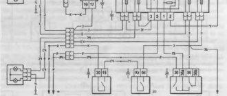
VAZ 2110 starter relay wiring diagram
Note: Please be advised that the bottom nut is quite difficult to access.
Assembling the starter and installing it in its original location occurs in the reverse order.
VAZ 2110 installation of an additional relay on the starter
The main malfunctions of the traction relay are several important problems. If one of the reasons is present, then the traction relay should be replaced with a new one.
VAZ 2110 starter relay clicks - needs to be replaced with a new one
If you continue to use a damaged relay in your car, other parts may suffer:
- In the case when the anchor stops rotating. The relay stops working after connecting the starter when starting the car.
- The same armature continues to rotate, but its speed is significantly reduced. This happens after activating the starter and connecting the traction relay.
- The starter works flawlessly, the traction relay is connected, but after a few seconds, the car engine “stalls”.
The main reasons for these problems may be:
- Interturn closure of the relay.
- Breaks in the power supply circuit.
- Untimely operation of the armature or its idle operation.
- Oxidation of wires, connections, windings.
- The nuts that secure the wire lugs have loosened and loosened the contact.
https://youtube.com/watch?v=JRhND312Zyk
- The traction relay is being replaced.
- Check and, if necessary, replace wires.
- The armature rotation must be returned to light operation.
- Clean the bolts and check the nuts for tightness.
Since the traction relay is part of the vehicle's electrical system, its repair or replacement must be carried out with care and special attention. This process can be dangerous to human health
The car can be entrusted to employees of technological service stations and repair shops. If you decide to carry out repairs yourself, you should follow all safety rules when working with electricity. Repair and replacement of equipment must be carried out on an observation platform or pit. A prerequisite is to remove the mudguard from the car engine. All the above steps must be carried out in strict order. After the process of dismantling the starter, you should perform a few more simple steps:
- The lower terminal of the traction relay has a fastening in the form of a nut. It should be unscrewed using a 10 mm wrench.
- The wire is disconnected there.
- Use a wrench with a stroke of 8 millimeters to unscrew the mounting bolts.
- The traction relay is removed.
- The gasket located between the front cover and the relay itself is disconnected.
- The front cover has a spring, an armature and a traction relay. They must be carefully removed from it.
Replacing the VAZ 2110 generator relay on your own
- 1 Checking the generator relay on a car 1.1 Checking the removed relay
- 1.2 Checking the capacitor
- 2.1 Advantages of three-level relay
- 3.1 Relay replacement
Relay regulator VAZ
Replacing the VAZ 2110 generator relay can be done in two ways: with removing the generator and without removing it. Both options can be done at home, although the second involves fewer manipulations with the car. But despite this, the first option may be simpler for some. Anyone can replace the VAZ 2110 generator regulator relay if they read and study the instructions below.
You can install the starter relay on the VAZ 2110 yourself
Those people who have a VAZ 2110 have certainly encountered a situation where the starter did not turn after the key was turned, and some clicks are heard, which indicate that the retractor relay is working. In such a situation, the question immediately arises: where is the VAZ 2110 starter relay located and how to find it faster. This question is also relevant when tuning a VAZ 2111.
But we have interesting news for you: the VAZ 2110 simply does not have a starter relay. There is a solenoid relay, to which the positive contact is supplied from the ignition switch. The relay is installed on the starter, its size is 2 times smaller than that of the starter, and it is round in shape.
Next, we will highlight some popular malfunctions that usually arise in the VAZ 2110, related to the VAZ 2110 starter relay and the starter; by the way, a lot of things are used in the VAZ 2115, so by tuning this car, many problems can be avoided.
Additional block
There is an additional block in the central panel, the location of which can be seen in the photo. It contains three fuses with the same power of 15A:
- The first is responsible for the controller and ignition module in the VAZ 2110.
- The second takes over the protection of the mass flow sensor (mass flow meter), purge valve, heating and speed sensor.
- The third is responsible for the injectors and fuel pump.
- The fourth number indicates an electric fan.
- Under the fifth is an electric fuel pump.
- The last relay relates to the ignition of the VAZ 2110.
Setup procedure
The minimum holding current of the thyristor (in this case on the KU101E thyristor) was 3.32 mA, therefore the current supplying thyristor VS1 through resistors R7 and R8 (Fig. 1) of the base circuit of transistor VT2 should be higher and is set by selecting these resistors.
In the case when the thyristor has a larger holding current, especially with a transistor switch VT2 of p-p-p conductivity, an additional ballast resistance is connected, it is possible with a construction resistor according to the principle of the circuit in Fig. 4.
What is meant here is that in a pnp transistor, unlike a pnp transistor, when the thyristor is open, current flows through the emitter-base circuit and through the open thyristor, the value of which depends on the current-limiting resistor.
Next, we charge capacitor C1. When relay K1 turns on, we close the circuit of capacitor C1, the capacitor will discharge. Relay K1 should turn off quickly, this should be repeated several times. In Fig. Figure 3 shows an alternative version of an electronic relay with improved capabilities.
The thyristor is turned on according to the current of the control electrode with a current greater than the holding current, and turned off - according to the current below the holding current. The device differs from the previous circuit in that the base of the transistor switch VT2 is connected between the anode of the thyristor VS1 and the cathode of the diode VD2, and the control electrode of the thyristor VS1 is connected to the anode of the diode or is connected to the emitter of the transistor VT1 through resistor R7.
Other ways to connect the control electrode are possible, for example, through a diode, zener diode, capacitor individually or mixed, or supplemented with a resistor. Thus, the base of the key of transistor VT2 is cut off from communication with “-”, including through the control electrode of thyristor VS1.
The following parameters were set on the KU101E thyristor during repeated tests: the holding current was 3.32 mA; at a lower current the thyristor was turned off. The minimum total current at which the thyristor opened again was 4.2 mA.
The voltage difference between turning off and turning on the thyristor at the common point of the emitter VT1 was 0.7 V. (It is worth noting that this principle can be used in tracking devices.) The holding time at the same ratings is the same as the circuit in Fig. 1, and the error is The device operates as follows.
When you press the SB1 button, the charging circuit of capacitor C1 is turned on. The positive voltage at the base will open transistor VT1. The current on the control electrode will cause the thyristor VS1 to open, the anode of the thyristor will accept a low potential, and the base of the transistor VT2 will receive a negative bias, which will completely open the emitter-collector junction of the transistor and turn on relay K1.
When the SB1 button is released, capacitor C1 will slowly begin to discharge when the minimum voltage at the emitter of transistor VT 1 reaches 1.5 V, and with a total current of less than 3.32 mA, the thyristor VS1 switches to the closed state.
The base of transistor VT2 will move to a positive bias and the transistor will switch to the closed state, relay K1 will turn off. In Fig. Figure 7 shows the printed circuit board of the electronic relay.
Rice. 7. Printed circuit board (method 2).
Basic starter malfunctions
The traction relay does not operate after the ignition key has been turned, and the armature does not rotate.
In this situation, it may be due to the following possible problems:
- the battery is broken or discharged, the solution to this problem is to buy a new battery or charge it;
- the positive contacts have oxidized - you just need to clean them;
- it happens that an interturn short circuit occurs on the winding of the traction relay - to correct this situation, you need to install a new relay;
- the circuit that powers the traction relay has broken - you need to check the wires for integrity, and whether they have become disconnected from the circuit?
- contacts “30” and “50” do not close - you just need to change the contact part of the ignition switch;
- The traction relay armature does not work well - you need to remove it and disassemble it, there may be a lubrication problem.
After turning the key, the starter does not start, the armature rotates slowly, and a click is heard in the traction relay.
This situation may arise due to previously similar situations:
- the battery is discharged or disconnected - you need to check and correct the situation;
- the winding of the traction relay is shorted or broken - you also just need to change the relay;
- the ends of the wires have seriously succumbed to oxidation - they need to be checked and cleaned, starting with the battery.
After turning the key, the starter armature spins, but the flywheel does not spin.
This situation arose due to the fact that:
- the freewheel is slipping - you need to diagnose the starter at the stand and replace the clutch if it is faulty;
- The gears on the gearbox are worn out - you just need to replace them.
The starter makes a lot of noise when the armature is spinning.
This problem arose because:
- The liners on the armature or drive shaft bearings have served their service life - you just need to replace the parts that have failed;
- the starter is not secured properly, and the cover could have broken - you just need to secure it or change it;
- the gears on the gearbox, flywheel crown or drive have failed - you just need to change them, or immediately replace the non-functioning parts entirely.
- the gear is constantly engaged with the flywheel; if the clutch on the shaft splines is stuck, it is possible that the armature of the traction relay is stuck - to solve this problem, you need to lubricate the splines with oil. And if the traction relay is stuck, then you need to either change it or use certain methods to get rid of the jam.