Modification of the VAZ 2110 generator
Refinement of the VAZ 2110 generator is considered a very useful improvement of the VAZ 2110, especially if you take into account the fact that many motorists, in recent times, are inclined to install additional units that consume electricity on their cars.
You can increase the voltage at the generator output in a variety of ways. Here, as they say, who is on what is much. For example, you can purchase and install a new, more powerful generator. Modification of the VAZ 2110 generator can be solved in another way. It is, of course, cheaper, although you will still have to spend a little, but it is also more labor-intensive. The charging voltage of the VAZ 2110 generator must correspond to that stated in the instructions and be 13.9 - 14.4 volts. To increase the efficiency of the generator, you can, for example, install a KD202V diode or a 2D219B diode in it, but it must be taken into account that the breakdown voltage must correspond to 20V, and the current must not be lower than 5A.
To modify the generator of a VAZ 2110 car, you can use the installation of a regulator from a foreign car with a voltage of 14.5V on the standard voltage regulator. It is necessary to remove the “pill” from the standard voltage regulator and install a “pill” from a foreign car in its place. All the work consists of proper installation and connection. It is necessary to carefully solder the output contacts of the “pill” of the foreign car to the standard body of the voltage regulator. I think you know how to do this as well as we do, but the conclusions will have to be adjusted a little. Then, you need to screw the tablet to the regulator body. All metal connections must be “sealed” with paint (screws, nuts) so that the structure does not fall apart during the vibration of the generator.
As a result of this modification of the VAZ 2110 generator, we increased its charging voltage to 14.5V. There are probably other methods of modifying the generator, for example installing an additional generator. But we'll talk about this next time.
Types of regulator relays
Before you independently repair the voltage regulation device, you must take into account that there are several types of regulators:
- external – increase the maintainability of the generator
- built-in – in the rectifier plate or brush assembly
- regulating by minus - an additional wire appears
- positive regulating – economical connection scheme
- for alternating current generators - there is no function for limiting the voltage on the excitation winding, since it is built into the generator itself
- for DC generators – an additional option for cutting off the battery when the internal combustion engine is not working
- two-level - obsolete, rarely used, adjustment by springs and a small lever
- three-level – supplemented with a special comparison device board and a matching indicator
- multi-level - the circuit has 3 - 5 additional resistors and a tracking system
- transistor - not used in modern cars
- relay – improved feedback
- relay-transistor - universal circuit
- microprocessor - small dimensions, smooth adjustment of the lower/upper threshold of operation
- integral - built into brush holders, therefore they are replaced after the brushes wear out
Attention: Without modification of the circuit, the “plus” and “minus” voltage regulators are not interchangeable devices.
DC generator relay
Thus, the connection diagram for the voltage regulator when operating a DC generator is more complicated. Since in the parking mode of the car, when the internal combustion engine is turned off, it is necessary to disconnect the generator from the battery.
During diagnostics, the relay is checked to perform its three functions:
- Battery cut off when the car is parked
- limiting the maximum current at the generator output
- voltage adjustment for field winding
Any malfunction requires repair.
Alternator relay
Unlike the previous case, diagnosing the alternator regulator yourself is a little simpler. The design of the “automotive power station” already includes the function of cutting off power from the battery while parked. All that remains is to check the voltage at the excitation winding and at the output from the generator.
If the car has an alternating current generator, it is impossible to start it by accelerating down a hill. Since there is no residual magnetization on the exciting winding here by default.
Built-in and external regulators
It is important for a car enthusiast to know that they measure and begin to regulate the relay voltage at a specific location where they are installed. Therefore, built-in modifications act directly on the generator, while external modifications “do not know” about its presence in the machine.
For example, if a remote relay is connected to the ignition coil, its work will be aimed at regulating the voltage only in this section of the on-board network. Therefore, before you learn how to test a remote-type relay, you should make sure that it is connected correctly.
Control by “+” and “–”
In principle, the control circuits for “minus” and “plus” differ only in the connection diagram:
- when installing the relay in the “+” gap, one brush is connected to “ground”, the other to the regulator terminal
- if you connect the relay to the “–” gap, then one brush needs to be connected to the “plus”, the other to the regulator
However, in the latter case, another wire will appear, since the voltage relay is an active type device. It requires individual nutrition, so “+” must be supplied separately.
Two-level
At the initial stage, mechanical two-level voltage regulators with a simple operating principle were installed in the machines:
- Electric current passes through the relay
- the resulting magnetic field attracts the lever
- the comparison device is a spring with a given force
- When the voltage increases, the contacts open
- less current flows to the exciting winding
Mechanical two-level relays were used in VAZ 21099 cars. The main disadvantage was working with increased wear of mechanical elements. Therefore, these devices have been replaced by electronic (contactless) voltage relays:
- voltage divider made of resistors
- The zener diode is the master device
Complex wiring and insufficient voltage control have led to a decrease in demand for these devices.
Three-level
However, two-level regulators, in turn, also gave way to more advanced three-level and multi-level devices:
- the voltage goes from the generator to a special circuit through a divider
- the information is processed, the actual voltage is compared with the minimum and maximum threshold values
- the mismatch signal regulates the current flowing to the exciting winding
Relays with frequency modulation are considered more advanced - they do not have the usual resistances, but the frequency of operation of the electronic key is increased. Control is carried out by logical circuits.
Modification of the VAZ 2110 generator (installation of a diode). When there is something to do
Installing additional equipment on a car requires increasing the on-board voltage, so modifying the VAZ 2110 generator (installing a diode) will be of interest to many. Modern domestic cars are increasingly equipped with additional equipment with each model. If the first VAZ models had generators providing a current of 40 amperes, today 80, 90, or even 100 amperes are becoming insufficient.
Many owners independently install additional power consumers, such as car subwoofers, fog lights and the like.
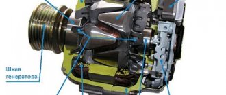
A few words about its structure
The generator set of this car is a fairly reliable device that can withstand vibration loads and temperature changes in the engine compartment. She is also not afraid of moisture and dirt getting in while driving. Its performance should be stable at any engine speed.
The main component of this device is the stator, which generates electrical voltage. It is installed between the halves of the body, front and rear. A rotor with an excitation winding rotates in a housing on bearings. Voltage is supplied to this winding through copper rings on the rotor shaft, and it is supplied to them through a brush assembly mounted on the back cover.
About possible improvements
. Today, lovers of additional consumers of electric current in a car have two ways to increase the battery charging voltage. Let's look at them.
Regulator relay diagnostics
Voltage regulator failures can be determined by indirect signs. First of all, this is incorrect battery charging:
- overcharge - the electrolyte boils away, the acid solution gets on the body parts
- undercharging - the internal combustion engine does not start, the lamps are dimly lit
However, it is preferable to diagnose with instruments - a voltmeter or tester. Any deviation from the maximum voltage value of 14.5 V (in some cars the on-board network is designed for 14.8 V) at high speeds or the minimum value of 12.8 V at low speeds becomes the reason for replacing/repairing the regulator relay.
Built-in
Most often, the voltage regulator is integrated into the generator brushes, so a level inspection of this unit is necessary:
- After removing the protective cover and loosening the screws, the brush assembly is removed out
- When the brushes are worn out (less than 5 mm of their length remains), replacement must be carried out without fail.
- Generator diagnostics with a multimeter are carried out complete with a battery or charger
- The “negative” wire from the current source is closed to the corresponding regulator plate
- The “positive” wire from the charger or battery is connected to a similar relay connector
- the tester is set to voltmeter mode 0 - 20 V, the probes are placed on the brushes
- in the range of 12.8 - 14.5 V there should be voltage between the brushes
- when the voltage increases above 14.5 V, the voltmeter needle should be at zero
In this case, instead of a voltmeter, you can use a lamp, which should light in the specified voltage range and go out when this characteristic increases above this value.
The wire that controls the tachometer (marked W only on relays for diesel engines) is tested with a multimeter in tester mode. It should have a resistance of about 10 ohms. If this value decreases, the wire is “broken” and should be replaced with a new one.
Remote
There are no differences in diagnostics for the remote relay, but it does not need to be removed from the generator housing. You can check the generator voltage regulator relay with the engine running, changing the speed from low to medium, then high. Simultaneously with the increase in speed, you need to turn on the high beams (at a minimum), the air conditioner, the monitor and other consumers (at a maximum).
Thus, if necessary, the vehicle owner can replace the standard voltage regulator relay with a more modern modification of a built-in or remote type. Diagnostics of performance is available on your own with a regular car lamp.
The proposed improvements to the regulator provide increased stability of the output voltage of a car generator when its load current and engine operating mode change. Modern cars have complex and multifunctional electrical equipment,
the reliable operation of which ensures the operability of the vehicle and the safety of its operation. The reliability of electrical equipment largely depends on the stability of the voltage in the on-board network. Ensuring that this voltage remains constant is a difficult task, especially during transient conditions when the generator rotation speed and its load current change sharply.
Together with a voltage regulator that maintains its constant, the generator forms an automatic control system. Under certain conditions, such a system may lose stability, which manifests itself in the form of sharp fluctuations in the output voltage of the generator and the charging current of the battery. Therefore, it is very important to ensure the stability of the control system under all operating conditions.
The most widely used today are electronic regulators operating in relay self-oscillating mode. Such a regulator, when the output voltage of the generator exceeds a given upper threshold, disconnects its excitation winding from the on-board network.
The current in the winding begins to decrease, which leads to a decrease in the generated voltage. As soon as it becomes less than the lower threshold, the excitation winding is reconnected to the on-board network and the current in it, and with it the output voltage of the generator, increases. Thus, the generator voltage fluctuates all the time, but its average value is maintained stable.
Regulators with “forced” PWM are more advanced. Due to the increased switching frequency of the excitation winding, the generator voltage in steady state is practically unchanged, although oscillations can still occur in transient modes.
Such regulators (one of them is described in the article by E. Tyshkevich “SHI Voltage Regulator.” - Radio, 1984, No. 6, pp. 27, 28) are not widely used, probably due to the fact that their parameters are not much better than conventional self-oscillating ones. Although they are mass-produced, they are difficult to find in stores. Sellers either know nothing at all about such regulators or claim that they are not in demand.
When operating a vehicle, an important parameter is the load capacity of the generator at low engine speeds. The minimum engine speed at which the battery is charged depends on it. Electronic voltage regulators most often lose stability precisely in situations where the rotation speed is low and the load current is high.
This feature is well known to motorists, some of whom replace electronic regulators with outdated contact-vibration ones, which are more reliable in this regard. But along with increased stability, they receive the disadvantages inherent in this type of regulator. Many motorists replace the standard battery with another one with increased capacity, as they believe that this improves the stability of the electronic regulators.
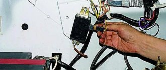
How to install an additional diode?
This is another way to modify the generator set to increase the battery charging voltage. This method is somewhat more complicated, since it will require complete disassembly of the generator. The modification consists of changing the connection of terminal D of the relay regulator.
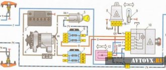
The diagram in red indicates an additional diode that needs to be installed. 2D219B device is well suited for such a semiconductor device.
, but you can choose a similar one with similar parameters.
You need to find about half a meter more of two-core wire, two terminals “male” and “female” number 4, as well as a heat-shrinkable casing. At one end of the wire, terminals are soldered and insulated with heat shrink. The free ends of the wire must be soldered to the diode, the “mother” is soldered to the cathode, and the “male” is intended for the anode. Now you need to connect the “mother” to the RN
, and the standard wire is connected to the “male”. At this point the modification is completed, all that remains is to assemble the device, install it on the car and carry out tests.
How to increase the voltage of a VAZ-2110 generator: increasing power
As you know, additional equipment is often installed on a car, which draws additional voltage from the on-board network. Thus, the voltage indicator on a VAZ-2110 can drop to a critical level of 11 volts. If you also install additional air conditioning or heated seats, this may result in the starter not having enough power to start the engine. How to fix the problem? Make sure that the voltage in the on-board network increases.
Video about increasing the voltage in the on-board network on VAZ cars:
Operating principle of the regulator relay
Thanks to built-in resistors and special circuits, the relay is able to compare the amount of voltage generated by the generator. After which, too high a value leads to the relay being turned off, so as not to overcharge the battery and damage electrical appliances connected to the on-board network.
Any malfunctions lead to precisely these consequences: the battery becomes faulty or the operating budget increases sharply.
Summer/winter switch
Regardless of the season and air temperature, the operation of the generator is always stable. As soon as its pulley begins to rotate, electric current is generated by default. However, in winter the insides of the battery freeze, and it replenishes the charge much worse than in summer.
The summer/winter switches are either on the body of the voltage regulator, or the corresponding connectors are marked with this designation, which you need to find and connect the wiring to them depending on the season.
There is nothing unusual in this switch, these are just rough settings of the regulator relay, which allows you to increase the voltage at the battery terminals to 15 V.
Connection to the generator's on-board network
If, when replacing a generator, you connect a new device yourself, you need to take into account the following nuances:
- First you should check the integrity and reliability of the contact of the wire from the car body to the generator housing
- then you can connect terminal B of the regulator relay with the “+” of the generator
- Instead of “twists” that begin to heat up after 1–2 years of operation, it is better to use soldering of wires
- the factory wire must be replaced with a cable with a minimum cross-section of 6 mm2 if, instead of a standard generator, an electrical appliance rated for a current of more than 60 A is installed
- The ammeter in the generator/battery circuit shows which power source is currently higher in the on-board network
We increase the voltage - all options for solving the problem
So, many motorists may decide that the way out of this situation is to install a high-power generator, but at the same time they will have to replace the battery with a more capacitive one. This is done in order not to “kill” the battery that is installed on the car, since a voltage overload will lead to the destruction of the internal cells. This option is not suitable because it is too expensive.
The second option is to install an additional diode from another diode bridge or marked KD202V. This is much cheaper than changing the generator and battery, but you will have to tinker a little.
To begin with, it is recommended to study automobile electrical circuits and the operation of the generator, as well as the charging circuit.
Manufacturing and installation of a diode in a VAZ-2114 generator
Now that everything is ready, we install an additional diode, more powerful than the previous one. You will need half a meter of wire 2*0.75mm. We solder the ends to the female and male terminals No. 4. We dress them in cambric, or better yet, in heat shrink. By the way, the old one must be removed from the system. Let's take action:
- Now, solder the following circuit to the diode: mother to the cathode, folder to the anode.
- We insulate the diode. For example, we take a film container.
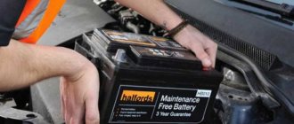
- We remove the “minus terminal” from the battery.
- We unscrew the “+” wires from the generator, disconnect the “D” wire to the tidy.
- Remove the generator cover.
- Through the slots in the cover, we connect the “mother” to the LV, the “father” to the standard wire.
- We carry out the assembly.
Now, everything is ready for the final check and measurements.
Modification of the VAZ 2110 generator
Refinement of the VAZ 2110 generator is considered a very useful improvement of the VAZ 2110, especially if you take into account the fact that many motorists, in recent times, are inclined to install additional units that consume electricity on their cars. You can increase the voltage at the generator output in a variety of ways. Here, as they say, who is on what is much. For example, you can purchase and install a new, more powerful generator.
Modification of the VAZ 2110 generator can be solved in another way. It is, of course, cheaper, although you will still have to spend a little, but it is also more labor-intensive. The charging voltage of the VAZ 2110 generator must correspond to that stated in the instructions and be 13.9 - 14.4 volts. To increase the efficiency of the generator, you can, for example, install a KD202V diode or a 2D219B diode in it, but it must be taken into account that the breakdown voltage must correspond to 20V, and the current must not be lower than 5A.
General design and repair of the generator.
Moor 2002, 2.0, Zetek engine, Motorcraft generator.
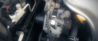
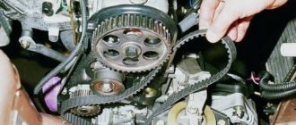
Of course, before removing it, you need to remove the belt tension roller. Slowly, at 30-40 degrees, the roller bolts are unscrewed, the main thing is to move the stubborn thread.
You can get to the bolts that hold the generator bracket on the cylinder block with the following tool - heads 13, 15, a Soviet tetrahedron and a Soviet adjustable wrench, a mirror and a flashlight, and also a mobile phone with a camera for where the mirror will not fit, since we are not snakes to twist our heads like that to see how the bolts and studs are located
The autopsy of the patient will have to be done completely, because the tablet and brushes are under the back cover. Americans Motorcraft generators make it so that the entire unit can be replaced. It’s on Boschs and Lucas that you can dodge and change the tablet without removing the generator.
The pulley nut had to be unscrewed in a barbaric manner - with a chisel and hammer while the rotor was fixed with a sprocket wrench. Damn, market traders valued a head of 22 at 10 raccoons. I respect my toad.
We managed to remove the covers by lightly tapping the ends around the covers with a hammer - the aluminum cast bearings came out fine. There is some play in the bearings, but it is acceptable.
Inspection of the armature showed the same result as the author of the thread - the commutator rings were worn down to zero to the point of plastic, one ring came off and shortened with the other, one brush was worn down to the control hole.
Anamnesis - look for the entire anchor... searched the market - nope. We go to the traders of new spare parts for generators, show the patient’s anchor, the traders measure the sizes of the rings with a caliper and say - out of stock. But they write a piece of paper with the inscription: “Current rings 233938.” We go further through the car market to the auto electrics pavilions.
So, 50% of the work is done - spare parts were purchased at a price significantly lower than the cost of the generator, you can go for a beer...
The beer is drunk, you can go home... by minibus. Beer is needed to impart business acumen, we will need it.
And so an inspection of the rotor showed that removing the old rings is problematic. The solution is beer, a hammer and a sharpened chisel. We bite the current whiskers from the rotor winding wires and CAREFULLY chop off the old plastic rings into pieces. Then we saw off or carefully cut off the arms of the fan impeller (using a cutting wheel will make it easier to remove).
the arms do not allow you to put on a new assembly of current rings, or rather the whiskers will rest against these arms of the impeller, so here you need to decide whether we are spoiling the impeller or spoiling the plastic on the tides of the conductors-whiskers of the current rings. The copper mustaches, with a square section of 2x2 mm, bend with force and will need to be somehow pushed under the arms at the same time as the rings are pressed on.
Having figured out what was what, the arms were eliminated. And why the Americans first press on the rings in the technical process and then put the impeller on the armature over the conductors making arcs is of little interest to us. Then we carefully tap and press a new assembly of current rings onto the shaft. In this case, we need to align the factory mark of the rings with the recess in the impeller. The third photo is visible. The output of the operation is this semi-finished product
Next, you need to solder the whiskers from the rings to the wires of the armature winding. The copper whiskers are cleaned with a sharp knife and tinned with rosin (!) and solder, then they are bent to the loops of the armature winding wires and soldered with a solid drop of solder. Excess pieces of mustache are bitten off. The impeller is now not a single whole and theoretically can fly apart at speed, but if it can withstand being cut with a chisel and breaking out pieces, it will live. There are signs that it is welded in a circle, not in spots, but in a continuous ring. The output is the following design:
Read more: Renault Megane 2 and 3 headlights left and right replacement tuning and adjustment of low beam lamps and PTF
After sealing, we assemble the generator “in a heap”. We insert the rotor into the front cover, put on the pulley and tighten the fastening nut into place with a wrench like an adjuster, securing the rotor from turning in the same way as in the photo during disassembly. Then we rotate the rotor by the pulley and use fine sandpaper to clean the slip rings from any burrs that were created at the factory during their manufacture.
Next, we put the stator winding in place, having first cleaned the end of the front cover from aluminum oxides (such a white mess is formed from all sorts of nasty things from the road)
then we put the voltage regulator “pill” in place.” Please note that the new tablet has a tricky wire that keeps the brushes retracted. This wire must be removed after installing the tablet and screwing it on.
And finally, we put the back cover of the generator in place by lightly tapping with a hammer and aligning the felt-tip pen marks made before unscrewing the bolts holding the cover together.
We put all kinds of plastic in place. It turns out that the unit's lifespan is almost similar to that of a new one, provided that the bearings on the rotor have not swung (have not yet been broken).
And now this generator needs to be mounted on a bracket, because it won’t be possible to push it back in separately, nor can it be taken out separately - when removed, the bolts rest against the spar and the scribe. At the same time, we finally tighten the pulley nut, securing the rotor from turning, remembering that the handy clamp should not damage the wires of the starter winding.
Well, now it’s an equally hectic procedure to push the bracket with the generator into place on the cylinder block. It's ugly because it's doughy. I would say you’ll have to twist a kind of Rubik’s cube, you’ll even have to disconnect the inlet air pipe from the throttle valves (by the way, you’ll see a lot of black stuff in the valves). The place where we hang the bracket with the generator looks like this
First tighten the top bolt. We tighten it lightly so that we can move the bracket, insert and screw in the remaining 3 bolts and 1 nut from the bottom, which are not visible, by touch. Again, use a mirror to aim where to insert the bolts from below and use your fingers to screw them in as fast as they can, before screwing the bolts you need to soak the threads in oil. We finally tighten it with heads, a bent wrench and an adjuster.
And finally, before installing the tension roller of the generator belt, trample the roller with your feet as it should on any wooden surface. The fact is that the spring there has rusted in one position and, in addition, the polyethylene boot may shrink due to time and temperature and the roller does not tension the belt, which can cause a characteristic creaking and squeaking sound of the belt on the pulleys on a cold engine.
This Canadian shrinking and warped polyethylene was brutally bitten out, the spring was dipped in oil and trampled until the “easy” movement was restored (watch your fingers). The roller itself was installed in place, its fastening bolts were tightened. Then the belt is put on the pulleys. You will have to pull the roller with one hand, and push a section of the belt under the roller with the other, and all this while lying on your stomach on the motor…. Well, everything is set in place...
While we were working on the generator, the battery was being charged from the charger in parallel, the multimeter reading showed 14.55V. The battery is charged and installed on the car. We measure the voltage again by turning on the side lights - 13.8V. We try to start it. The key is to start - the instrument needles again jump to their extreme positions, after a couple of seconds they cheerfully go to zero, the gasoline needle returns to the true fuel level. This makes me happy.
The airbag, engine, oil pressure and ABS lights went off as usual, the nasty battery light is on normally, which means the brain has been loaded. Start the starter - the smoking room starts up, drives the idle up to 1500, fills the fuel and ignition matrix, the generator makes a familiar buzzing sound with a whistle - charging is in progress.
Read more: Instructions for installing a towbar on a VAZ 2110 and 2112
We put a multimeter on the battery terminals and see what comes from the generator 14.55V when the tablet promises 14.6. Fine. You can travel. Total labor costs - 4 hours on Saturday to disassemble, 8 hours on Sunday to purchase and assemble. This was in July. After 2.5 months, I measured the voltage again with a dial gauge - it’s normal, the needle doesn’t move, so the brushes don’t jump around the rings, they’ve gotten used to it. A multimeter will not provide such information.
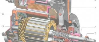
The generator structure is shown in the photo. The housing (5) and the front cover of the generator (2) serve as supports for the bearings (9 and 10), in which the armature (4) rotates. Voltage from the battery is supplied to the armature field winding through brushes (7) and slip rings (11). The anchor is driven by a V-belt through a pulley (1).
When starting the engine, as soon as the armature begins to rotate, the electromagnetic field it creates induces an alternating electric current in the stator winding (3). In the rectifier block (6) this current becomes constant. Next, the current through a voltage regulator combined with a rectifier unit enters the vehicle’s electrical network to power the ignition system, lighting and alarm systems, instrumentation, etc.
The conditions in which the generator has to operate cannot be called favorable. The generator gets exposed to dirt, oil, moisture, salt, the harmful effects of which are aggravated by high air temperatures in the engine compartment. To reduce the effect of salt baths to a minimum, to prevent oxidation of the generator output terminals and, for this reason, loss of reliable contact in them, it is recommended to keep the fastenings of all generator wires under a layer of some kind of grease.
Particular attention must be paid to the tension and timely replacement of the V-belt or multi-ribbed generator drive belt. Do not allow the generator to operate even for a short time with the battery disconnected. A voltage surge in the network that occurs when the battery is disconnected, for example to test a generator, is dangerous for almost all on-board electronic devices of modern cars.
How to correctly replace the generator diode bridge on a VAZ 2110?
As you know, a car generator is designed to provide power to all electrical equipment in the car when the engine is running. This unit in domestic “tens” consists of many elements that ensure its optimal operation. One such device is a diode bridge. What functions does it perform, what do you need to know about its malfunctions, and how is the diode bridge of the VAZ 2110 generator replaced? You can find answers to these and other questions below.
Causes of breakdowns
As numerous checks show, the main cause of breakdowns is factory. Here, first of all, you need to pay attention to the shell in which the diodes are located. If it is aluminum, it is better not to take such a unit. Much more reliable is steel.
In addition, if the seller does not provide a guarantee, you should be wary. According to reviews on the Internet, the most unreliable diode bridges are made in Belarus.
Step-by-step instructions for repairing the VAZ 2110 generator are located here: https://vazweb.ru/desyatka/gena/remont-generatora.html
- Another reason is moisture ingress, which results in oxidation of the space between the diode itself and the housing;
- Contact of oil or other working fluids of the VAZ 2110 on the surface;
- If you reverse the polarity of the battery while lighting or charging, the diode bridge can easily “fly out”;
- You can also suspect that the VAZ 2110’s rectifier is failing if the battery stops charging.
Using a multimeter it is very easy to check the serviceability. Need to:
- Place the positive probe of the multimeter at the positive diode bus;
- Do the same with the negative probe and the “-” diode output;
- This test, if the diode bridge is working properly, should give readings close to infinity. If this is not the case, there is a malfunction and needs replacement;
- Now we swap the probes (put plus to minus and vice versa);
- Let's look at the readings. If the unit is working properly, the readings should be several hundred ohms;
- To check the additional diode, perform the same steps as described above.
Description of the diode bridge on the “Ten”
How is the diode modified and installed in the device? For what reasons can a bridge fail? To begin with, we suggest that you familiarize yourself with the description of the part. If you dismantle the generator assembly from the car and remove the cover, you will be able to see the diode bridge (DM), which is located immediately behind it.
Purpose and functions
What functions does the DM perform:
- The primary task of the device is to convert alternating current into direct current.
- The DM also performs the function of blocking current from entering the stator winding. In this case, the device actually performs the one-way valve option.
- In addition, the DM is designed to increase the safety margin of the generator unit. It allows you to protect the mechanism from the effects of adverse factors and contamination on the device, and this, in turn, can negatively affect the functionality of the mechanism as a whole.
Device
As for the device, in the factory configuration the DM for the “tenth” generator is a monolithic structure. This design, as a rule, is quite strong and reliable, is characterized by its small size, as well as a relatively low price. The only drawback characteristic of factory-made DMs is that if one of the diode elements burns out, local replacement of the damage will not be possible. That is, the car owner will have to completely change the factory axle with his own hands.
As for the design features itself, the DM consists of:
- two aluminum plates;
- spacers made of plastic;
- as well as nine diodes, which are connected to each other by soldering into one structure, that is, a bridge.
Malfunctions of rectifiers on cars
A malfunction of the rectifier bridge can be detected if:
- When the engine is running, the battery icon on the instrument panel lights up or flashes; when you turn on the ignition, the indicator should light up. After starting the engine - go out;
- When the ignition is turned on and after the engine starts, the charging indicator with the battery icon does not light up in both cases;
- The brightness of the headlights directly depends on the engine speed. At the same time, car light bulbs burn out more frequently;
- The starter turns, with difficulty starting the engine, or does not turn at all.
If you encounter the problems described above, this means that it’s time to work on the generator. These are indirect indicators of a malfunction of the diode rectifier, but it is not yet a fact that the bridge is at fault. The culprit in this case may be the relay regulator or the generator itself. Therefore, further verification needs to be carried out.
First of all , check to see if the belt is loose . Insufficient belt tension causes slippage. And this prevents the generator from working normally. After checking the belt, if everything is fine with it, we check the relay regulator. And only after this we begin to check the rectifier bridge. By the way, be sure to check the battery. The terminals must be clean and the wires securely fastened to them.
How to check a diode bridge with a multimeter
This check can be done without removing the generator from the car. To do this, you will need a multimeter (tester) and free access to the back cover of the generator. If access is difficult, it is better to remove it. In any case, disconnect all external wiring from the generator and remove the voltage regulator.
After that, take a multimeter and set the switch to diode testing mode. If it is not there, then we set the resistance to at least 2 kOhm to measure. Next, we connect one of the probes to the positive terminal 30 of the generator (a stud on which usually two to four wires go and are secured with a nut), and connect the second one to ground (housing). Then we swap the probes. In one case, the measuring device should show a certain resistance, in the second - infinity. This way the entire circuit of the rectifier bridge is checked. If the tester shows the same result in both cases, then the rectifier bridge is faulty.
Checking the bridge using a test light
For further and more accurate checking, it is best to use a test light . If it is not available, we assemble a simple circuit. To do this, you will need two pieces of electrical wire, one meter each, a light bulb (can be removed from the rear light of the car) and a battery. We connect one wire to the negative of the battery. We cut the second one in half and connect a light bulb into the gap. We connect this wire to the battery positive. Our stand is ready for use.
Now you can continue checking. We connect the negative cable of the battery to the generator housing. The positive one with a light bulb - with one of the diode rectifier mounting bolts. If the light comes on, it means there is a malfunction inside the generator.
Then we connect the plus of the battery to terminal 30 , and connect the minus to the bridge mounting bolt. If the light is on in this case, this indicates the presence of a short circuit.
In any of the above cases, we disassemble the generator, remove the diode bridge and check it separately.
Generator diode bridge ringing
First, remove the plates with rectifier diodes . Some generators need to be disassembled for this, but there are those in which the rectifier bridge is located outside, covered with a plastic cover.
Let's look at checking the diode bridge of the generator of the VAZ 2110 car. Checking the diode assembly can be done with a multimeter or the stand described above using a light bulb and a battery. On the tester we set the mode switch to 2 kOhm.
To check, connect the multimeter probes to the diode terminals. We remember the reading of the measuring device and swap the probes. In one case, the tester readings should be in the range of 570 - 590 Ohms, in the other - infinity.
If the tester readings are the same in both cases - it doesn’t matter what it is, resistance or infinity - then such a diode is faulty. In this case, we replace the entire rectifier bridge. The prices of voltage rectifiers on the market are relatively inexpensive. You can also change a faulty diode, it will be cheaper, but this requires a certain skill. The remaining diodes of the bridge are checked in the same way.
How to check the diode bridge of a VAZ 2109, 2107 generator? All of the above-described testing of diode assemblies is suitable for both domestic and foreign generators. The process and principle of checking rectifier bridges is the same everywhere. Sometimes there are some differences, but they do not affect the check order in any way.
Other rectifiers
There are many other rectifier bridges in electronic equipment, the size of which is much smaller than those described above. For example, diode bridge GBU606. Such rectifiers can easily fit into a matchbox, and not just one rectifier unit, but several pieces. It is rectangular in shape. One corner has a small cut. At the end of the long side there are four thin plates. With these plates it is soldered to the board. And although the characteristics of the GBU606 have significant differences from automobile ones, the principle of operation and purpose remain the same. This is the conversion of alternating current to direct current.
Possible malfunctions: signs and causes
As stated above, the purpose of diode elements is to convert alternating voltage to direct voltage. If one of the diode elements fails, then its malfunction may be indicated by such a sign as a decrease in the voltage level, as well as power in the vehicle electrical network.
For what reasons may problems occur in the operation of the DM:
- Manufacturing defects. As practice shows, many modern DM manufacturers use aluminum shells of fairly low quality in their production. Accordingly, this affects their reliability as a whole. That is why it is recommended to use DM equipped with steel shells, since this directly affects the service life.
- Moisture gets inside the device. Regular exposure to moisture can cause oxidation, in particular, on the surface between the device body and diode elements.
- Engine fluid getting into the unit is one of the most common causes. Exposure to lubricant can lead to disruption of the functionality of the device as a whole, especially if it gets inside the generator unit, directly on the DM.
- Another reason why DMs on “tens” often fail is the polarity of the battery is reversed. If you connect the battery to a charger or accidentally reverse the polarity while “lighting up” the car, this will most likely cause the motor to burn out. Therefore, you should always remember that plus is connected to plus, and minus is connected to minus.
- Regular operation of a vehicle with a weak battery. If the battery does not pull the load and constantly operates under conditions of reduced charge, then the reason may be the inoperability of the DM.
Causes of malfunctions
The practice of motorists shows that replacing a diode bridge can be caused by various reasons, but the main one is still a feature of factory production.
It will be useful: Land Rover Freelander 2 timing belt: do-it-yourself replacement
Therefore, let's take a closer look at the reasons for rectifier failure, which may lead to the need to replace the device.
Cause
Peculiarities
Many manufacturers use aluminum shells for diodes, which are not of high quality and reliability. It is recommended to choose steel shells. The experience of specialists and motorists shows that the best rectifiers today are made in Belarus
Moisture can penetrate inside the structure and lead to oxidation of the space between the housing and the diodes
Oil also leads to disruption of the functionality of the device if it penetrates inside the generator structure and specifically onto the diode bridge
Battery polarity confusion
If, when connecting a battery to a charger or when lighting a cigarette, you accidentally reverse the polarity, this will most likely lead to a breakdown or burnout of the bridge
If the battery does not hold power and constantly has a weak charge, the rectifier may be the culprit
Before you start replacing the device, you must first check the generator and bridge, thereby making sure that the rectifier is the culprit of the problem.
Advantages of a factory rectifier
Many people believe that when repairing a car it is better to use analog spare parts, which are more expensive but of higher quality. This is a fair statement for many spare parts, to be sure.
But if we are talking about a rectifier, then for a VAZ 2110 when replacing it is better to use the factory version, that is, a monolithic diode bridge.
This is explained by several important advantages. Namely:
- Affordable price, which allows you to perform inexpensive repairs yourself;
- Small size, compact device;
- The diodes used interact effectively with each other, their parameters match optimally;
- Due to the high-quality arrangement of diodes, the bridge operates in a single heating mode. This, in turn, allows you to avoid overheating with a high degree of probability;
- Easy to replace and install. The procedure is easy, which allows you to do the repair yourself.
Diagnostics
The diagnostic procedure must be carried out on a dismantled generator device, so the unit must first be removed. When the mechanism is dismantled, the plastic cover is removed from it, as mentioned above, the DM is located immediately behind it (the author of the video about self-diagnosis with a multimeter is Ramil Abdullin).
For diagnostics you will need a tester - a multimeter - the test is carried out as follows:
- First, the multimeter should be activated in ohmmeter mode. Having done this, the positive probe of the tester must be connected to the diode bus.
- In the same way, connect the negative probe of the tester to the corresponding contact on the diode bridge.
- Next, you need to monitor the tester readings. If the diode bridge is in working condition, then the tester display will show values close to infinity. If there are no such values, then most likely the DM is inoperative and should be replaced. But the diagnosis does not end there.
- Next, you will need to swap the location of the probes, that is, the negative contact is connected to the positive one and vice versa. Having done this, again look at the multimeter reading on the display. If there are no failures in the operation of the DM and the device as a whole is functioning normally, then a value of several hundred Ohms should appear on the tester screen.
- If the DM is equipped with an additional diode, then you can check it too. In this case, the diagnostic procedure is performed in a similar way; you just need to repeat all the steps.
Photo gallery “Self performance test”
Checking status
Checking the diode bridge is quite simple, even on your own. There is no need to go to a service station.
All you need is a multimeter.
- We connect the positive probe of the multimeter to the diode bus.
- Similarly, we connect the negative probe to the negative terminal of the diode bridge.
- Now let's look at the device readings. If all is well with the rectifier, then you will see readings close to infinity on your multimeter. If none appear, then there are problems with the device and you will have to change it.
- But that's not all. Now the probes should be swapped, that is, the minus should be connected to the plus, and the plus to the minus.
- Let's look at our multimeter again. What do you see there? If several hundred ohms, the unit of measurement for resistance, are displayed, then the unit is operating normally and is in good working order.
- To check the additional diode, if any, repeat the same steps described above in our instructions.
Replacement
If checks show that there is something wrong with the diode bridge, there is nothing left to do but replace the device. There is nothing complicated about this. Especially if you have already had to disassemble the generator or at least remove it.
Follow the proposed algorithm and additionally rely on video instructions. This will help you cope with the task.
- Disconnect the battery. To do this, just remove the negative terminal from it.
- Disconnect the pink wire that turns on the generator. To do this, you will need to unscrew the mounting nut from the positive bolt.
- Loosen the tension of the upper and lower nuts slightly, unscrew the tension bolts, and remove the belt. You can put it aside for now.
- Rotate your alternator 90 degrees so you can remove the bottom mounting bolt.
- Carefully inspect your generator housing. The rectifier housing may need to be cleaned. If there is contamination on it and on the connections, it would be a good idea to clean it. This will allow the new device to function more efficiently and effectively.
- Try to be as careful as possible, but at the same time thoroughly clean the inside of the ring.
- Remove the old diode bridge and then perform the reassembly procedure.
- Start the engine and check the functionality of the new rectifier.
Dismantled element
Reassembly is carried out in strict sequence, taking into account the individual design features of the new generator rectifier.
Based on the materials provided and the replacement instructions, you should be able to complete the task without any problems. But if problems arise, be sure to contact a specialist.
DIY replacement instructions
In the event of a breakdown, the repair of the DM consists of its replacement, which is done as follows:
- First you need to turn off the ignition, open the hood and turn off the power to the on-board network; to do this, disconnect the battery.
- Once the battery terminal is reset, you will need to disconnect the pink cable responsible for activating the generator assembly. The wire itself is fixed with a bolt and nut; the nut itself will need to be unscrewed.
- Now you need to slightly loosen the tension on the top as well as the bottom nuts. Unscrew the tension screws and remove the strap. Inspect it - if the belt shows signs of damage - cracks, delamination - then it is better to change it immediately. If the strap is intact, set it aside.
- After completing these steps, you need to rotate the generator mechanism 90 degrees, this is done so that you can access the lower mounting screw. Unscrew it.
- Next, carefully inspect the body of the dismantled unit. Clean if necessary - there should be no dirt, especially on the connections. Dirt getting inside the generator housing can also lead to its incorrect operation and even failure. Bend the fasteners and remove the cover.
- Next, you need to clean the inside of the rings as carefully, but most effectively as possible.
- After this, all you have to do is dismantle the failed DM and replace it with a working part. When the installation is completed, the structure is assembled in the reverse order. Do not forget to tighten the strap, just make sure that it is not too tight, this is important. Having done this, you will need to start the engine of your car and diagnose the operation of the new DM.