The use of a generator for the home in most cases is intended as an alternative source of electricity when the current in the stationary network disappears. With frequent interruptions, this is especially necessary to protect electrical equipment.
To accurately obtain the required current strength and stable voltage, you should buy a generator with improved technical characteristics and from a reliable manufacturer. This determines how long and successful the operation of the unit will be. After the purchase, the question becomes obvious - how to connect the generator to the house, which we will discuss in this article.
What types of generators are there?
Many people think that generators and uninterruptible power supplies are mutually interchangeable and identical. But that's not true. UPS are devices that provide current only for a while. Their work is just enough to save important information on the computer, for example. The generator can produce electricity many times longer.
There is another device that many also confuse with generators. These are voltage stabilizers . They equalize the voltage if surges occur in the network. Stabilizers protect equipment from sudden changes in network voltage, thereby extending the service life of electrical appliances.
Before answering the question of how to connect a generator to the home network, you need to understand which generators can be connected to the home network.
There are three main types of generators based on engine type:
- gasoline;
- diesel;
- gas.
A gasoline generator is used only for a short time; its operation is not suitable for long-term loads. If the main power source is, then gasoline units should be purchased only to maintain the operation of the devices for a short time (up to 12 hours), if there are frequent network outages.
The diesel generator is the most powerful unit. This is, in fact, a diesel station that can continuously generate electricity, or be used as a backup generator for lighting the house.
Gas generators consume the least amount of fuel, which is why they are considered the most economical generators. They can operate either from a gas cylinder or from a gas main.
Also, both gas and gasoline can be used as fuel in one generator - with the ability to switch. They are called dual-fuel .
There are two more types of generators - inverter and welding. Both gas and gasoline can be used as fuel.
Inverter generators have a distinctive feature - performance adjustment. For example, during a power outage, all appliances in the house are connected to the generator. If you turn off any device, automatic performance adjustment will work, and the generator itself will reduce the load.
Welding generators are designed to power welding machines, mainly manual ones.
The number of phases and the cooling system also depend on the type of generator.
Based on the number of phases, generators are divided into single-phase (output voltage 220 V) and three-phase (380 V). The first are used in residential buildings where there is only one power and ground line. A three-phase generator provides power via three power lines, with one grounding line.
Generators use air or liquid cooling . The first is used on generators or power plants whose power does not exceed 6 kW. Liquid cooling is installed on more powerful generators, the number of engine hours of which is about thirty thousand. It is better to buy such generators on official websites or in specialized stores to prevent interference with the device by unscrupulous sellers.
How to connect a three-phase generator?
In the case of using a switch, a winding is required for each phase separately, that is, a jumper from one phase to another.
VAZ-2107 instrument panel diagram
The instrument panel is an important part of every car, and the 2107 is no exception. For visual perception, it is better to look at what the VAZ 2107 “tidy” diagram looks like.
1 — automobile voltmeter;
2 - speed indicator or, more simply put, speedometer;
3—machine trip meter—odometer;
4 - tachometer. It shows the frequency at which the crankshaft rotates. The yellow zone on the scale indicates that the engine is running at high speeds; the red zone indicates unacceptable modes. 6000 rpm is the maximum permissible speed.
5 - coolant temperature indicator. The green zone is the normal coolant temperature. The red zone indicates engine overheating. The vehicle must not be operated at a coolant temperature exceeding 118 °C;
6—econometer. This indicator helps you select the most economical mode for engine operation from all modes (the instrument needle should be in the green zone of its scale).
7 - block (CL) of warning lamps of the VAZ 2107 car:
— turning on the turn indicators (when turning on a left or right turn, it lights up with a flashing green light);
— malfunction of the engine control mechanism (used on a car with an injection power unit. The lamp glows orange if the ignition is on. When the engine starts, it goes out). If there is a malfunction in the system, the lamp flashes or is constantly on. In such a situation, using the car is not prohibited, the system will simply switch to backup mode;
— battery charge lamp. When the ignition is turned on, the lamp on the instrument panel turns red and goes out when the engine starts. If the lamp continues to light, the battery is not charged. There may be several reasons: the generator drive belt is insufficiently tensioned, the control lamp or generator circuit is faulty. If you continue to use the car, this may lead to the battery being completely discharged and the engine stopping. A fire may also occur;
— side light indicator (lights up green if the side lights are on);
— indicator for turning on the high beam of the car’s lighting devices (the lamp lights up blue if you turn on the high beam of the headlights);
— insufficient oil pressure. When the ignition is turned on, the oil pressure lamp begins to glow red and immediately goes out when the engine starts. If the light remains on, there is low oil pressure. To avoid failure of the power unit, you need to turn it off and try to eliminate the cause of the malfunction;
— the parking brake is on (the lamp lights up bright red if the ignition is turned on and the parking brake lever is raised).
8—indicator of the path traveled per day;
9 — (CL) fuel reserve. The yellow light comes on if there is less than 6-4 liters of fuel left in the fuel tank;
10 — fuel level indicator;
Where is the best place to install a generator?
The generator can be connected both outdoors and indoors. If the generator is installed outdoors, care should be taken to protect it from snow, rain, and the external environment. To do this, you can use a container or a special protective casing. It is not safe to install it under a regular canopy.
Since the generator engine makes a lot of noise during operation, it is necessary to take care of sound insulation in advance.
When choosing an installation location, you need to take into account the type of generator start . It is better to place devices with a manual (cable starter) or electric starter (ignition key/button) closer to the house or in the basement. This will allow you to run a backup source even in severe bad weather.
With remote or automatic (AVR) starting there is no such need. AVR stands for “automatic transfer of reserve”. The automation is triggered when the voltage in the network disappears, and the generator starts automatically. This method is also called emergency.
General useful information
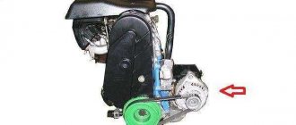
The VAZ 2107 generator converts the mechanical energy of rotation of the engine crankshaft into electrical energy. It is also intended to power the entire on-board network, and is also necessary to recharge the battery. To convert alternating current to direct current, the unit is equipped with a rectifier unit, which consists of six diodes. A special relay-regulator serves to maintain the voltage at a given level. This device is located outside the generator.
When the ignition is turned on, the voltage, passing through the vehicle's warning lamp, reaches the regulator, and from it is transmitted to the excitation winding. It is powered by three diodes. They are located in the rectifier block. If the warning lamp continues to light during startup, this means that the battery is not sufficiently charged. You need to check the voltage status of the on-board network. If it is below normal, it means:
- a short circuit has occurred in the network;
- there are faults in the battery;
- a malfunction of the automobile relay-regulator has occurred;
- malfunction of the VAZ 2107 generator.
In this situation, you should check the belt tension, as well as the condition of its bearing, and see if the relay regulator is working. It would be a good idea to look again at the expiration date and actual condition of the battery. If everything is normal, but the voltage is not enough, you need to contact a specialist auto electrician. The generator of the presented car model does not require special care. You just need to make sure that water and dirt do not get on it. You should also check the condition of the belt (it needs to be tensioned, approximately as in the video), and it is also important that the bearing is constantly lubricated and does not create noise during operation.
1200 rub. for the photo report
We pay for photo reports on car repairs. Earnings from 10,000 rubles/month.
Write:
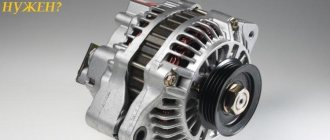
The most basic function of the generator is to charge the battery and power the electrical equipment of the engine.
A generator is a mechanism that converts mechanical energy into electrical energy. The generator has a shaft on which a pulley is mounted, through which it receives rotation from the engine crankshaft.
How to calculate generator power?
Before installing the generator, it is necessary to correctly calculate the generator power. To do this, you need to add up the power of all appliances in the house and choose a generator with a power reserve.
There is a rated power - in this case the load is variable, and the average power should not exceed 80%; and maximum power (it is designed for 500 hours of operation and should not exceed 90% of the load). For example, the rated power is 2.5 kW, then the maximum power is 2.8 kW.
Design Features
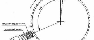
The operating principle of a car generator is based on the effect of electromagnetic induction, which makes it possible to receive an electric current by inducing and then changing the magnetic field around the conductor. To do this, the generator contains the necessary parts:
- rotor - a coil inside two pairs of multidirectional magnets, receiving rotation through a pulley, and direct current to the field windings through brushes and commutator rings
- stator - windings inside the magnetic circuit in which alternating electric current is induced
- diode bridge – rectifies alternating current into direct current
- voltage relay - regulates this characteristic within 13.8 - 14.8 V
Rice. 2 Generator design
When the engine is not running, at the moment of starting it, the excitation current is supplied to the armature from the battery. Then the generator begins generating electricity on its own, switches to self-excitation, and completely restores the battery charge while the car is moving.
At idle speed, recharging does not occur, but the on-board network and all its consumers (headlights, music, air conditioning) are provided in full.
Stator
The most complex part of a generator is the stator structure:
- from transformer iron 0.8 - 1 mm thick, plates are cut out with a stamp;
- packages are assembled from them (welding or fastening with rivets), 36 grooves around the perimeter are insulated with epoxy resin or polymer film;
- then 3 windings are placed in bags, fixed in the grooves with special wedges.
Rice. 3 Generator stator
It is in the stator that alternating voltage is generated, which the car generator later rectifies into direct current for the on-board network and battery.
Rotor
When using rolling bearings, the journal is hardened, and the shaft itself is created from alloy steel. A coil covered with a special dielectric varnish is wound on the shaft. Magnetic pole halves are placed on top of it and secured to the shaft:
- look like a crown;
- contain 6 petals;
- are made by stamping or casting.
Rice. 4 Generator rotor
The pulley is fixed on the shaft with a key or a nut with a hex key. The power of the generator depends on the thickness of the excitation coil wire and the quality of the varnish insulation of the windings.
When voltage is applied to the field windings, a magnetic field appears around them, interacting with a similar field from the permanent pole halves of the magnets. It is the rotation of the rotor that ensures the generation of electric current in the stator windings.
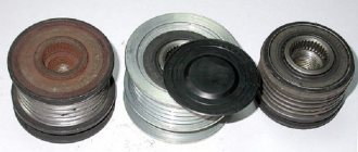
Current collection unit
In a brush generator, the structure of the current collection unit is as follows:
- the brushes slide along the commutator rings;
- they transmit direct current to the excitation winding.
Electrographite brushes wear out less than copper-graphite modifications, but a voltage drop is observed on the collector half-rings. To reduce electrochemical oxidation of rings, they can be made of stainless steel and brass.
Rice. 5 Generator current collection unit
Since the operation of the current collection unit is accompanied by intense friction, brushes and commutator rings wear out more often than other parts and are considered consumables. Therefore, they are quickly accessible for periodic replacement.
Rectifier
Since the stator of an electrical appliance generates alternating voltage, and the on-board network requires direct current, a rectifier is added to the design, to which the stator windings are connected. Depending on the characteristics of the generator, the rectifier unit has a different design:
- the diode bridge is soldered or pressed into horseshoe-shaped heat sink plates;
- The rectifier is assembled on a board, heat sinks with powerful fins are soldered to the diodes.
Rice. 6 Generator rectifierFig. 7 Diode bridge option with independent radiators
The main rectifier can be duplicated by an additional diode bridge:
- sealed compact unit;
- dida-pea or cylindrical shape;
- inclusion in the overall scheme by small buses.
The rectifier is the “weak link” of the generator, since any foreign body that conducts current, accidentally falling between the heat sinks of the diodes, automatically leads to a short circuit.
Voltage regulator
After the alternating amplitude is converted into direct current by the rectifier, the generator power is supplied to the voltage regulator relay for the following reasons:
- The internal combustion engine crankshaft rotates at different speeds depending on the type of driving, travel distance and vehicle driving cycle;
- therefore, a car generator by default is not physically capable of producing the same voltage at different periods of time;
- The regulator relay device is responsible for temperature compensation - it monitors the air temperature, and when it decreases, it increases the charging voltage and vice versa.
This is interesting: Design features
The standard temperature compensation value is 0.01 V/1 degree. Some generators have manual summer/winter switches that are located in the interior or under the hood of the car.
Rice. 8 Voltage regulator
There are voltage regulator relays in which the on-board network is connected to the generator excitation winding with a “–” wire or “+” cable. These designs are not interchangeable, they cannot be confused; most often, “negative” voltage regulators are installed in passenger cars.
Bearings
The front bearing is considered to be on the pulley side, its housing is pressed into the cover, and a sliding fit is used on the shaft. The rear bearing is located near the collector rings; on the contrary, it is mounted on the shaft with interference; a sliding fit is used in the housing.
In the latter case, roller bearings can be used; the front bearing is always a radial ball bearing with a one-time lubricant applied at the factory, which is enough for the entire service life.
Rice. 9 Generator bearing kit
The higher the generator power, the greater the load the bearing race experiences, and the more often both consumable parts need to be replaced.
Impeller
The friction parts inside the generator are cooled by forced air. To do this, one or two impellers are placed on the shaft, sucking air through special slots/holes in the product body.
Rice. 10 Generator impeller
There are three types of air-cooled car generators:
- if there is a brush/collector ring assembly and the rectifier and voltage regulator are moved out of the housing, these components are protected by a casing, so air intake holes are created in it (position a) of the lower circuit;
- if the arrangement of the mechanisms under the hood is dense, and the air surrounding them is too hot to properly cool the internal space of the generator, a specially designed protective casing is used (position b) in the lower figure;
- in small-sized generators, air intake slots are created in both housing covers (position c) in the bottom figure).
Rice. 11 Options for generator air cooling schemes
Overheating of the windings and bearings sharply reduces the performance of the generator, and can lead to jamming, short circuit and even fire.
Frame
Traditionally, for most electrical appliances, the generator housing has a protective function for all components located inside it. Unlike a car starter, the generator does not have a tensioner; the sagging of the transmission belt is adjusted by moving the housing of the generator itself. For this purpose, in addition to the mounting tabs, the body has an adjustment eye.
The body is made of aluminum alloy and consists of two covers:
- The stator and armature are hidden inside the front cover;
- Inside the back cover there is a rectifier and a voltage regulator relay.
Rice. 12 The generator housing consists of two covers
The correct operation of the generator depends on this part, since a rotor bearing is pressed inside one cover, and the belt is tensioned in the eye of the housing.
Electrical diagram
Manufacturers take into account the specific number of consumers in a car model, so in each case an individual electrical circuit of the generator is used. The most popular are 8 diagrams of “mobile electrical installations” under the hood of a car with the same designation of elements:
- generator block;
- rotor winding;
- stator magnetic circuit;
- diode bridge;
- switch;
- lamp relay;
- regulator relay;
- lamp;
- capacitor;
- transformer and rectifier unit;
- battery;
- Zener diode;
- resistance.
Rice. 15 Scheme 1
In schemes 1 and 2, the exciting winding receives voltage through the ignition switch so that the battery does not discharge when parked. The disadvantage is the switching of 5 A current, which reduces the service life.
Rice. 16 Scheme 2
Therefore, in diagram 3, the contacts are unloaded by the intermediate relay, and the current consumption is reduced to tenths of an ampere. The disadvantage of this option is the complex installation of the generator, decreased reliability of the design, and the switching frequency of the transistor increases. The headlights may blink and the instrument needles may shake.
This is interesting: Description of the distinctive features of the engine and the stages of its development
Rice. 17 Scheme 3
In circuit 5, an additional rectifier is made from three diodes on the way to the excitation winding. However, when parking for a long time, it is recommended to remove the “+” from the battery terminal, as the battery may be discharged. But during the initial excitation of the winding at the moment of starting the internal combustion engine, the battery current consumption is minimal. Extinguish the zener diode, which is dangerous for the electronics of the machine.
Rice. 18 Scheme 5
For diesel engines, generators using circuit 6 are used. They are designed for a voltage of 28 V; the exciting winding receives half the charge due to connection to the “zero” point of the stator.
Fig 19 Scheme 6
In diagram 7, the discharge of the battery during long-term parking is eliminated by reducing the potential difference at the “D” and “+” terminals. An additional wing of the rectifier diode bridge was created from zener diodes to eliminate voltage surges.
Rice. 20 Scheme 7
Scheme 8 is usually used in Bosch generators. Here the voltage regulator is complicated, but the circuit of the generator itself is simplified.
Rice. 21 Scheme 8